output of PID
Hello
I have problems with my pid in the sense that it displays only 2 values(min_and_max).i have tried different gains and yet it will not work properly.can someone help me please? the process I'm tring to control is an oven, and I use NEITHER 6024E and CSC-2345. (I also tried without the dt s, using a simple wait in the while loop, but it is not influence it)
Your output range is tiny (0 to 0.02). In the meantime your comments seems to be on a much larger scale. Your P gain being 20, any error (difference between setpoint and variable processes) greater than 0.001 will be enough to drive the full output or full out (20 * 0.001 = 0.02). You need either a larger output range (and then scale before you send the output to the DAQ hardware) or much smaller gains (which could result in the loss of some mathematical precision).
Tags: NI Software
Similar Questions
-
Output of PID VI looks to On / Off signal
Hi all
I'm new to requests for PID and currently starting a project involving the PID of a heater of air command. I came across some problems and I'd appreciate really all of the suggestions here

The installation consists of a cDAQ-9174 with RTD module (for example NOR-9217) and an output module current (NOR-9265). The process variable is the incoming temperature which is extracted from the RTD, and current output module sends the output of PID of 4-20mA to the incubator, 4mA is equivalent to heating off, and everything above that turns heater at different levels as a result.
I found a sample program on the site OR I have changed according to my installation. PID loop rate is 10 Hz, and for this I used the calendar software (please see the attached VI). The output for the PID VI range is set to 4-20mA.
During execution of the program, we can see RTD works well (process variable updates correctly), but the output of the PID VI signal varies between these two extremes (4 MA or 20 MA), which apparently turned into a On / Off attached template instead of PID (see the "On-off MV.jpg" screenshot). As a result, the oscillating system in undesirable ways.
I looked at the example LabVIEW, ran to some of them, programs and they seem to work well. I also looked to their diagrams and outside the middle range output different (default is from-100 to 100), I can't see any significant difference for the other parameters to the PID VI.
Was there everything I hard set, or was there something I missed? Any help will be greatly appreciated... Thank you!!
Best regards
Victor
If you want to be using PID loops you need to learn about the setting of a PID. There is a lot of information around on the internet on how to do and there are different methods depending on who you talk to.
How is it tuned and the small selected output range will make things very quickly. What you can do is to change the output of pid to 0-100 range. Then you can use the percentage of PID to EGU vi use the output of the pid to control your 4-20mA signal. So the 0-100 =.004 A02. Then, you must always set the PID to your system.
-
Basic concept of loop PID closed
Hello
I have a problem of very basic concept of PID loop closed. I read a lot of material of the PID controller but still confused.
I understand that the error between the measure and the desired will be processed by PID controller, but I do not understand how the controller output (sum of three P/I/D) set the right plant behand the controller. For example, an electric motor fan will be below on a Board, the force of the wind on the motherboard could be detected by the tension and of course the fan speed could be adjusted by tension. But the error of the setpoint and the process variable will go directly to the fan in Labview without identifying the mechanisms on the plant (fan). I wonder if anyone knows how this error is treated by the plant. And why we need not care about the transfer of the factory function.
If you have a transfer function for your plants, you don't need PID, because the output of the optimal control can be determined directly from the transfer function! (Well, more specifically, often in this case you would use the transfer to feed-forward control function, which you would combine with PID to correct minor variations between the reality and transfer function model.)
The output of PID is not a sum of errors. It is a sum of the outputs of regulation - the proportional output, the full output and the derived products output. The gains set the regulator to the specific system, and if they are not chosen correctly, the control will be terrible and potentially unstable.
In your hypothetical example of two systems - Yes, it is quite possible that one moment the error and so the output will be the same. But if the systems are very different, the next iteration of control errors will be different, so the next controller output value will be different, etc. And if the systems are very different, they should not have the same gains.
-
PID position control: guide me
Dear Member
I want to build a position of PID control
I read the DC position by potentiometer with 360 degrees-128 to 127 [complete]
If the pid entry is range of voltage between-128 to 127
the entrance of motor continuous is PWM and the direction of motor rotation
If the output of PID is PWM
What bit of direction? What will be this tour
also how to control the speed in the same system? is Taylor PID another?
Best regards
mangood wrote:
What, control the position and speed at the same time?
It's a complicated problem. A quick search on the internet turned to the top of this article that describes some possible approaches:
-
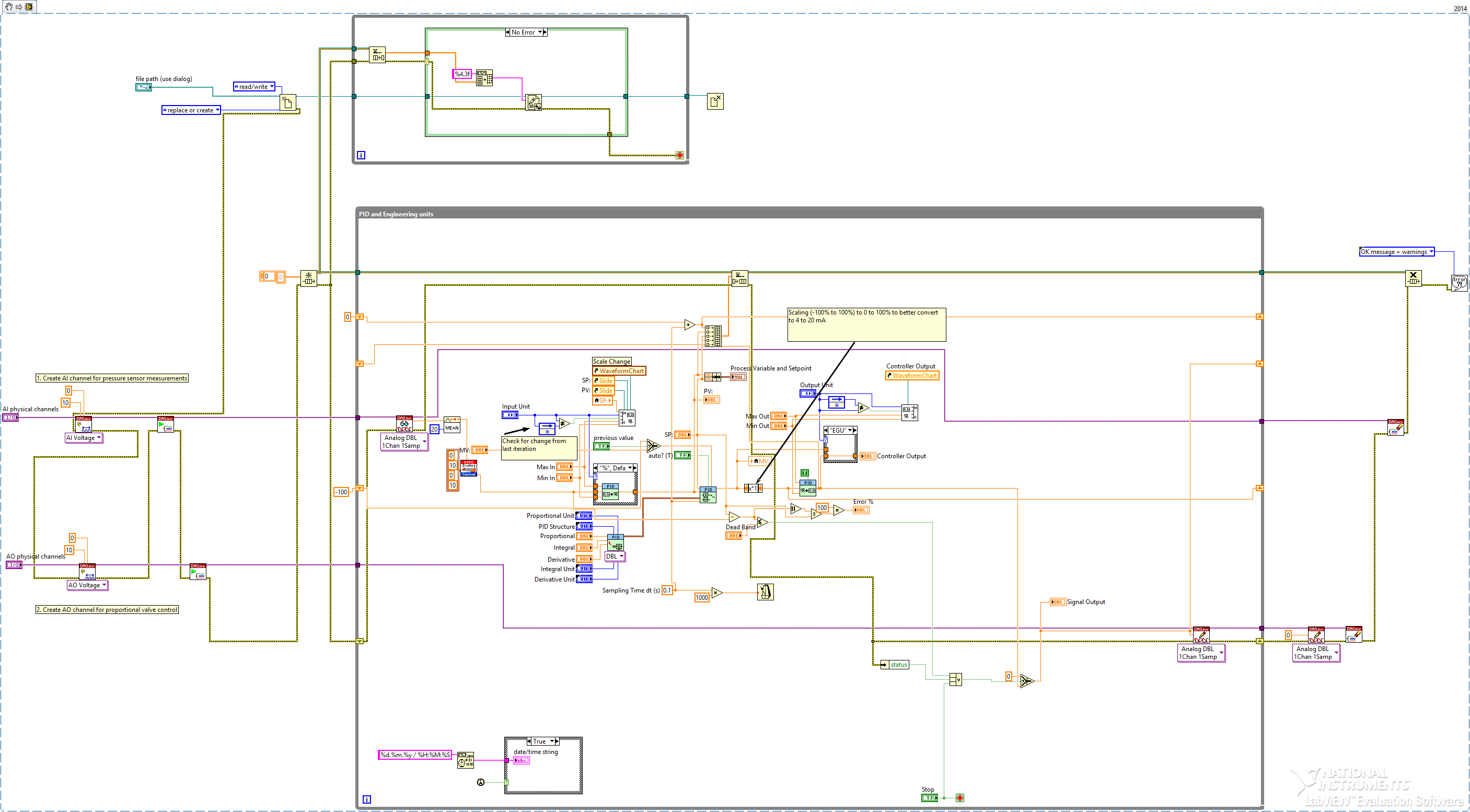
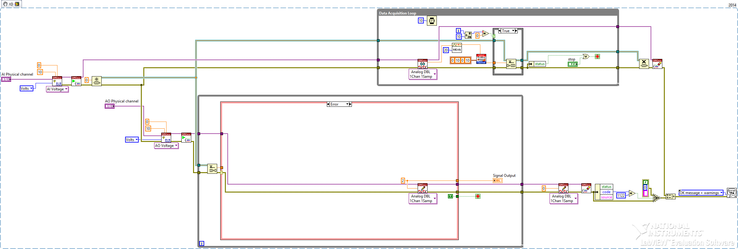
Screw of PID can work in a loop of consumer?
Hi all
I'm working on the proportional valves with PID control. To do this, I have prepared a vi based on a design of producer-consumer model, however, it does not work. When I use a while loop incorporated all daq reading, writing and control tasks, it works. I'm confused about this.
You can see these two screws, one of them works the other not (based on the producer-consumer model), below, and also in the attachment.
Newbieeng - why you re the PID differently between the two versions (a single loop against two), then assume that the difference in performance was the result of the number of loops and not unlike the logic?
Following what GerdW wrote on the EGU % calculation, follow the math to explain what is happening. Evolve you your process Variable for a percentage of the value between 0 and the set value. It is, as already mentioned, a preposterous calculation. If your set point and your process variable are the two 0-10, then by converting the process variable to a percentage of the range of 0-10 will almost always the percentage being greater than 10. For example, if your process variable is 2 bar and your set point is 5 bar, the output will be 40%. Thus, the entries of your PID (which you should have probed, so you see what is happening) are a set of process point and 2 variable 40! 40 much larger than 2, the output of PID would be negative, but you have limited it to 0 - explaining why you get always 0 output. It has nothing to do with the producer and the consumer compared to a single loop.
-
Hello
I'm trying to implement the PID loop, but face some problems.
Entry:-the engine in terms of PWM feedback fixed duty cycle and variable frequency.
Output:-is set to frequency and vary the duty cycle.
Observation is regardless of setpoint motor is running in the range defined by PID output range.
Please help solve this thing.
Attachment:-exit running Vi & Vi also rasthaus.
Hi Nitin,
so limit you the output of PID to a very small range range - and then you wonder, why the PID regulation is not outside this small beach of work?
Output:-is set to frequency and vary the duty cycle.
BTW. Why do you establish exit [1700, 1900] when you want to a duty cycle as output value? What kind of cyclical report uses values such as '1800 '?
-
I use a counter that is generated by a PCI-6110 to switch a relay to solid state that enables or disables a heating unit. I update the duty cycle based on the output of a PID controller (0 - 100 output of PID VI gets scaled to a cycle of 0.001 to 0.99). The question is after two iterations, the written property node is no longer the output of PID on the scale to the task and it seems 0 as the default value.
Many meter generation examples use event structures to detect a change in the duty cycle and pass that to the task. But structures event detect changes in values if the value is written in a local variable and not typed in a CNC? I feel that the answer should be 'Yes'... but in the case I tested it seems to be 'no '.
Don't adjust the precision of a digital indicator / control limits the number of significant digits does a calculation? I would limit my duty cycle to 2 decimal places - i.e. 0.3342 and 0,3313 the two would be 0.33. In this way the cycle is not unnecessarily updated.
The temperature is read by a PCI-4351... which may arise under? blocks if you have not installed the drivers.
arcranda wrote:
Many meter generation examples use event structures to detect a change in the duty cycle and pass that to the task. But structures event detect changes in values if the value is written in a local variable and not typed in a digital control?.
To have a triggered event when a value is changed programmatically, create a Value property node (signaling) and the new value of wire to it. This will trigger a change of value for this variable event.
arcranda wrote:
Don't adjust the precision of a digital indicator / control limits the number of significant digits does a calculation? I would limit my duty cycle to 2 decimal places - i.e. 0.3342 and 0,3313 the two would be 0.33. In this way the cycle is not unnecessarily updated.
.
Changing the properties of display to show only 2 decimal places does not change the numeric value stored in memory. You would have to round up the digital to two decimal places. To do this is to multiply the number by 100, change of an integer (this will lose the remaining decimals), then divide the result by 100 to get again the two decimal places. When changing to an integer, you will need to round to the nearest integer to make 0.3299 0.33.
-
Sequence structure flat inside the timed loop and execution order
I have some problems trying to implement a flat sequence structure when you use a loop timed on a target of cRio VI
I tried with or without the while loop around the structure of sequence flat, and I also tried to replace the 'Non-deterministic loop' with a timed loop
The problem is that the program seems to run only once, then get stuck somewhere
I am writing a program that performs the following operations as soon as possible:
1. read the Pos_MC of entry on the FPGA
2 send the value of Pos_MC to the VI target (on cRio CPU)
3. calculate a value of output based on Pos_MC with a PID block ("exit PID')
4. send 'PID output' to the FPGA
5 write "PID output" analog output "MOOG".In addition, I want the program to return the measured value "Pos_MC" to a host VI for the recording of data
So that the output of PID is calculated and sent to the FPGA as quickly as possible, I placed a flat sequence structure to ensure that it happens before you send the output to the nondeterministic loop for recording data
Also, I want the digital input 'Stop' to be able to stop the loop deterministic (the timed loop)
I read much more entries than that and the help of several PID and exit, but I rewrote the code for a single entry and exit to make it easier to illustrate
Screenshot of the code is shown in 'target code.png' and 'fpga code.png.
The VI themselves are attached in the next post (cannot attach files of more than 3)
Question 1:
Any advice on how to get this race? Thank you!Question 2:
Is also my correct understanding in that, using this structure, each 0.9ms (fpga loop time) comes the following:
1. the input ("Pos_MOOG") is read on the fpga
2. the production of PID is calculated on the cRio with some delay to computation (for example 0.1ms)
3. the output of PID is then written for analog output "MOOG" in all about 0, 1 - 0.2ms
4. the FPGA program then waits until 0.9ms spent and repeat the processAs opposed to the next pass whenever performing a loop is started on the FPGA:
1. the FPGA reads the input and written on the output (the output of the execution of the previous loop PID)
2. then the entry is sent the cRio, PID output is calculated and sent to the FPGA
3. the new release of PID is maintained until the next time through the loop
Thank you!
PHG wrote:
Thanks for the input guys, any advice as to how I could get the feature in scenario 1?
I still say that the best route is just putting all the logic of the control in the FPGA.
Other alternatives include 1) the use of DMA FIFO sedn data back or 2) use interruptions so that the FPGA code can not read the output level until the RT.
DMA FIFOs are usually very limited, and I would not use them in this situation since I belive said it this code to do for the many outputs.
-
Hi all
Could someone help me please?
I need rank/order one set of data by date and period type (blocktype) records of worker groups. When the blocktype "Ind (individual)", I need to increment the row by 1. Where the type is "Cont (inuous)", I don't want to increment the row until the next "IND record." This is how I can get then the start/end dates of min/max for this rank number.
I don't know if it's clear, but it's really obvious what should I do with the attached SQL below (see column 'Désirée'). I'm guessing that rank and dense_rank is the way to go, but I don't know what is the combination of the columns of the partition/drive by?
If anyone could help'd me smile. :)
Thank you.
create the table mytable
(pid varchar (10),)
StartDate date,
date EndDate,
BlockType varchar (4),
desired varchar (1));
insert into mytable (pid, startdate, enddate, blocktype, desired) values ("A123", to_date('23/10/2007','DD/MM/RRRR'), to_date('05/11/2007','DD/MM/RRRR'), 'ind', 1);
insert into mytable (pid, startdate, enddate, blocktype, desired) values ("A123", to_date('16/11/2007','DD/MM/RRRR'), to_date('19/11/2007','DD/MM/RRRR'), 'ind', 2);
insert into mytable (pid, startdate, enddate, blocktype, desired) values ("A123", to_date('26/11/2007','DD/MM/RRRR'), to_date('25/04/2008','DD/MM/RRRR'), "cont", 3);
insert into mytable (pid, startdate, enddate, blocktype, desired) values ("A123", to_date('25/04/2008','DD/MM/RRRR'), to_date('28/08/2008','DD/MM/RRRR'), "cont", 3);
insert into mytable (pid, startdate, enddate, blocktype, desired) values ("A123", to_date('01/04/2009','DD/MM/RRRR'), to_date('09/09/2009','DD/MM/RRRR'), 'ind', 4);
insert into mytable (pid, startdate, enddate, blocktype, desired) values ("A123", to_date('01/05/2010','DD/MM/RRRR'), to_date('03/05/2010','DD/MM/RRRR'), "cont", 5);
insert into mytable (pid, startdate, enddate, blocktype, desired) values ("A123", to_date('03/05/2010','DD/MM/RRRR'), to_date('19/11/2010','DD/MM/RRRR'), "cont", 5);
insert into mytable (pid, startdate, enddate, blocktype, desired) values ("A123", to_date('19/11/2010','DD/MM/RRRR'), to_date('06/02/2011','DD/MM/RRRR'), "cont", 5);
insert into mytable (pid, startdate, enddate, blocktype, desired) values ("A123", to_date('29/04/2011','DD/MM/RRRR'), to_date('14/11/2011','DD/MM/RRRR'), 'ind', 6);
Published by: user9363122 on October 28, 2011 16:35Hello
Little Penguin says:
In this case, I have to get the start date and end date for the period of the child to education where the code start is (s, B) and the end code! = X.In the sample data you posted, it looks like a begions period again whenever startcode is either a ' or 'B' and that endcode has nothing to do with it:
insert into mytable3 (PID, StartDate, Enddate, StartCode EndCode, desired) values ('A657', to_date('11/12/2008','DD/MM/RRRR'), to_date('24/12/2008','DD/MM/RRRR'),' to, 'X', 1);
insert into mytable3 (PID, StartDate, Enddate, StartCode EndCode, desired) values ('A657', to_date('24/12/2008','DD/MM/RRRR'), to_date('22/05/2009','DD/MM/RRRR'), 'P', 'X', 1);
insert into mytable3 (PID, StartDate, Enddate, StartCode EndCode, desired) values ('A657', to_date('22/05/2009','DD/MM/RRRR'), to_date('25/11/2009','DD/MM/RRRR'), 'P', 'E', 1);
insert into mytable3 (PID, StartDate, Enddate, StartCode EndCode, desired) values ('A657', to_date('04/05/2010','DD/MM/RRRR'), to_date('17/06/2010','DD/MM/RRRR'),' to, 'X', 2);
insert into mytable3 (PID, StartDate, Enddate, StartCode EndCode, desired) values ('A657', to_date('17/06/2010','DD/MM/RRRR'), to_date('19/07/2010','DD/MM/RRRR'), 'B', 'E', 3);
insert into mytable3 (PID, StartDate, Enddate, StartCode EndCode, desired) values ('A657', to_date('29/09/2010','DD/MM/RRRR'), to_date('23/11/2010','DD/MM/RRRR'),', 'E', 4);
insert into mytable3 (PID, StartDate, Enddate, StartCode EndCode, desired) values ('A657', to_date('14/01/2011','DD/MM/RRRR'), to_date('20/04/2011','DD/MM/RRRR'), 'P', 'E', 4);
insert into mytable3 (PID, StartDate, Enddate, StartCode EndCode, desired) values ('A657", to_date('20/04/2011','DD/MM/RRRR'), null, 'B', null, 5);In the above data, periods 2 and 5 do not contain an enddate = 'E '.
That's why I need assign a dense_rank
It doesn't have to be a DENSE_RANK, t - it? As long as you get good results, you will not care if DENSE_RANK or some other function produces these results, right?
based on the first startup code for the first end code, the second beginning at the end of the second code code, the third code beginning at the end of the third code etc. sorted by start date.
... I thought that it might be possible using row_number()?Good idea, but it could be even better ways to do this.
The ROW_NUMBER analytic function has all rows .
The analytical COUNT function counts only certain lines . In the following query, there are only lines where startcode in ('B', the from '):SELECT m.* , COUNT ( CASE WHEN startcode IN ('B', 'S') THEN 1 ELSE NULL -- This is the default, but you can explicitly say it if you want to END ) OVER ( PARTITION BY pid ORDER BY startdate ) AS period FROM mytable3 m ORDER BY pid , startdate ;To find the startdate and enddate in the whole of the period, this in a subquery and then use the analytical MIN and MAX functions, like this:
WITH     got_period     AS
(
     SELECT     m.*
     ,     COUNT ( CASE
                         WHEN  startcode IN ('B', 'S')
                  THEN  1
                      ELSE  NULL     -- This is the default, but you can explicitly say it if you want to
                     END
                   )     OVER ( PARTITION BY  pid
                            ORDER BY          startdate
                    )     AS period
     FROM     mytable3     m
)
SELECT       p.*
,       MIN (startdate) OVER (PARTITION BY period)     AS period_startdate
,       MAX (enddate)     OVER (PARTITION BY period)     AS period_enddate
FROM       got_period  p
ORDER BY  pid
,            startdate
;
Output:
PID   STARTDATE  ENDDATE    S E DE     PERIOD PERIOD_STA PERIOD_END
----- ---------- ---------- - - -- ---------- ---------- ----------
A657  11/12/2008 24/12/2008 S X 1           1 11/12/2008 25/11/2009
A657  24/12/2008 22/05/2009 P X 1           1 11/12/2008 25/11/2009
A657  22/05/2009 25/11/2009 P E 1           1 11/12/2008 25/11/2009
A657  04/05/2010 17/06/2010 S X 2           2 04/05/2010 17/06/2010
A657  17/06/2010 19/07/2010 B E 3           3 17/06/2010 19/07/2010
A657  29/09/2010 23/11/2010 S E 4           4 29/09/2010 20/04/2011
A657  14/01/2011 20/04/2011 P E 4           4 29/09/2010 20/04/2011
A657  20/04/2011            B   5           5 20/04/2011
Why do I say you must use a subquery to get period? Discuss.
-
Hi guys,.
Im a software using advanced LabVIEW PID and hourly programming. But as my gain change, the output does not accordingly with my gain. For example:
Error = 10
Gain = 10
Output = 100
Then
Gain = 0, 01
Output = 100 supposed to be output = 1
Looks like transfer smoothly? I couldn't tell.
Yo have any idea why? The VI of "PID Gain schedule example" change accordingly with the error output. But mine is not. I hope you guys could help

Not the Gain annex vi does not change your output according to the entry it will select all of the gains that you want to use. In a certain type of profiles, we will have to use a different set of earnings, so in these cases, you can have a different set of gains and which apply accordingly. For your business simple PID must be suffucient.
-
PID does not return any output...
Hello everyone...
process sbRIO on board and using the audio and vibration Simulator
below I have attached my RT + FPGA... code to control the speed of the fan... using PID...
RT. front panel
set range
1000, -1000
set point... 5000 RPM (speed is the parameter)
PID GAINS...
the values calculated at the time of the executin arbitraty... KC = 1, gain full (Kc * Ts/Ti) = 0.011718,.
derivative gain (Kc * Td/Ts) = 0
other considerations
Maximum speed of the fan is 6000 RPM
tachometer on the vibration signal Simulator is 2 impulses/turns
the speed is measured accurately
Manual disturbance can be given by varying the analog output voltage
If the pid is introduced into RT it works fine...
but, when the pid (in fpga) is introduced not able to disturb and also not output to
all other parameters is reset (final rpm, out outputanalog)
all equal to zero
This data set is meaningless... I suggest that you check that you actually save the correct values, and you have the wired PID controller correctly upward.
There are times when (?) heated, but the speed does not change. Also there are times where speed (?) has a step increase, but there is no change in voltage. You can also see places where 5V is applied but different speeds are generated. Of course, it would be much clearer if you labeled your data, including units.
Open-loop can the system actually achieve 4000 rpm with the applied 5volts? Try to start with a set point which is at the centre of its work.
The ramps are integral single action? What gains have used here. You should try proportional only first of all, make sure that everything is working properly and then only start watching full action.
-
Where is the initial output PID Terminal?
Hi all
I'm upgrading from the code from LabVIEW old something to LV8.6.1, which uses the PID Control Toolkit. I see that in .vi PID (table dbl), the initial outputs can be set using the outputs Intial input terminal. In the last toolkit PID, things were simplified and now there seems to be no way to adjust the outputs initials?
It is important that I can do this, because the system will begin to control a platform that is already running. Initial results are set to the settings at the time of the takeover, and which ensures a smooth transition between user control and automatic control. But if I can't set out initial, I think that PID control code everything is set to zero at its first iteration. This could be catastrophic?
If I do not take into account the results of the iteration, then let it take control of the second iteration from, is that going to help? Or will there be another (though less bumpy) switching between manual and automatic modes?
All the most popular boards. Thank you
The advanced PID VI (in the PID toolkit) has an option 'Manual' that allows to change smoothly from manual to automatic operation.
-
Updated a case of pid output structure
Hi, I have a vi attached and add another case to my business structure so I can adjust the market factor of a pwm with vi running output. I currently wired it to the cycle with a thread of split. I can set my duty cycle and temperature changes, but my winnings of pid setting has no effect. Can someone please help me on what I am totally lost! Whenever I try to add another case that I get just the broken wires. Thank you
-
LabView PID control with PWM output and ramp / soak.
-
Hello world.
I wrote a program of temperature control in labview and used the PID Toolkit for it.
The entrance to the PID is the measured temperature and the output is a PWM signal fed to a relay that turns heater on or off.
The control works but I want the temperature to be stable within a range of + - 2%.
Currently, the temperature varies more than that.
IAM sure, this is the setting of the PID.
Because I have not worked with regulators PID Iam not exactly how to tune my system.
The best way I found is to zero I and D and make the system oscillate with P.
The only problem is that the system of temperature is so slow that it takes quite a long time to reach the set point which in turn would mean a lot of hours of tests only.
Now Iam just wondering if there is a faster way to set the PID controller?
Thanks in advance,
Best regards
Michael
I've used this method several times with slow heating appliances. It can take a long time to reach a stable temperature, but at least do not monitor constantly as he approaches this value.
In figure 3.4, Yes, the Min value is the initial value that is stable. It is OK to start an initial PWM output of 0, which speeds up the process, if your radiator is already at a steady temperature (the temperature in the room).
In general, the difference between the output of the first and the last values, better will be your control (you will get best results of going from 0 to more than 50% to 5%), but it will take more time to settle to a new value and of course you must ensure that you do not exceed the capabilities of your system. It's a good idea to have a separate alarm system in place that can cut power to heater if you exceed a temperature, especially if you plan to walk away from it until it stabilizes.
To a fixed cycle, the system will not continue to heat up indefinitely unless you have a perfect insulation without heat loss - but, as I mentioned above, do not choose a value that will not cause the system to overheat.
Maybe you are looking for
-
I upgraded to Thunderbird 31.1.0 yesterday. I have not modified the distribution list in the last few weeks. This is the first time I used the distribution since the upgrade list. I never got an error message from the mail server who oppose my distri
-
I have problem acchisessing this site named http://gifthulk.com The connection has expired What should i do? I tried in different browsers, erased by cache, cookies and also reinstalled firefox. But it does not work, what should I do?
-
Wrong display of fonts Tamil in iCloud accessed via a browser (Mac or PC)
Hello I created a document in Mac using Pages. I typed in Tamil and the police displayed correctly. I transferred this document to iCloud and opened in 'Pages for iCloud' from your Windows PC. Here the police was NOT displayed correctly. I tried vari
-
'Aid for this VI' in the executable
When my vi runs as an executable file I need help/support for the IA function this menu to open an html help file that I wrote. I am unable to say in the main vi or the executable to build where this.
-
I was doing some research on SNMP and MIBs.Hit a roadblock when this question came to my mind. Windows stores all MIBs under %SystemRoot%\System32 I know that these MIBs are used to send traps. I just want to know the throughput, or how it's done. Wh