Output of REST
I'm pretty new to the REST, and I understood how to run a workflow through the REST. Works very well, but what I'm trying to understand is how to retrieve the results. I have a workflow that displays all virtual machines in a cluster in an output called vmArray parameter. I can run the workflow via REST very well. I can see the State of enforcement, etc. How to actually get the contents of the variable however? I couldn't find any example online. Any help is appreciated. Thank you
Mike
See my article here: http://bit.ly/restvco
Look in the section: results expected of the POSITION
The Location header will provide you with the token of workflow. Perform a GET against this url to see the output of your workflow (this should have information similar to what you see when you view a workflow runtime in the customer to vRO... only in XML or JSON according to how you put your headers)
Hope that helps
Tags: VMware
Similar Questions
-
Output of REST Orchestrator API
How do you get the output of a workflow using the REST API?
In the example below, I ran the workflow to call an external script to call a powershell script external which connects to a vCenter and gets a list of all hosts. The output is visible in the client Orchestrator, but what format the object must be converted to be seen in the output of the API?
I would like to be able to run a workflow through the API to extract data in JSON and display that in an external web page. Someone at - it all example workflows that would do that?

You must copy the object to a string.
Check the method. getAsJson() of a PowerShellRemotePSObject.
So wrap the workflow "invoke an external script" in a custom workflow, add a script task after the workflow, when you run this method, and bind the result to an output channel of your custom workflow parameter.
Kind regards
Joerg
-
Measured values of task not aggreeing with the measurements of the test Panel
We read (with excitement) accelerometers using modules PXI-6254. Initially, we thought that we were see shift CC and we were and we filtered. Now, if we measure the sensor output at rest with an O'scope we read uV. For even if we read the channels with MAX test panels we also read some uV. But when we do the DAQmx tasks and look at the tensions of the task to MAX (same sensors at rest), we see readings of up to 25 or 30 mV - orders of magnitude higher. Can anyone suggest what may be the cause?
(I enclose a word with screenshots represetative doc)
Thank you
lmd2
How many channels are tailor-made and at what rate? What is the output impedance of the accelerometer or filters, you have between the accelerometers and the 6254?
It is possible that you run into error when paying. The specifications for the PXI-625 x cards has a chart showing the expected setting vs error track-to-track interval various sources.
A way to test this would be to slow down your sampling rate. If the error decreases as you slow down the sampling frequency, it's a good bet that you run into a problem of setup time.
Mark Moss
Electrical Validation engineer
GHSP -
Service Web REST-output parameter does not work in the Manager POSITION
I created a RESTful Web Service in Oracle Apex, using a POST method as a 'Manager' I have installation 11 input parameters which all work fine, this is my setting an output that does not return successfully.
Here are details on the output parameter
Name: returns
Name of the bind Variable: : return
Access method: OUTPUT
Source type: response
Parameter type: String
The actual source is a call to a pl/sql package that returns a value that I set: Returns equal to (for example: Returns: = v_result). I tried this with header Type of Source and still the same result, "no exit".
I see APEX calls wwv_flow_api.create_restful_param to generate the (import) settings, is there documentation on this procedure?
How can I get this output parameter to return something to the answer?
The application accepts a load of Json.
Any help greatly appreciated
Thank you
James
Solved my problem: feedback does not need to go back
Does not work
Name: returns
Name of the bind Variable: : return
Access method: OUTPUT
Source type: response
Parameter type: String
WorksName: returns
Name of the bind Variable: returns
Access method: OUTPUT
Source type: response
Parameter type: String
-
Error in the REST Web Service with the text output Format
Hi all
I am referencing a REST web service and can successfully connect to it and retrieve the results with the output XML value Format.
I don't need the node values, I want to just grab the entire XML string and fill a table with her column.
When I create a new Rest web service reference, including the text output Format value and then create a form/report to run it, I get the following error when I click on "send":
ORA-06550: line 1, column 63: PLS-00103: encountered the symbol "end-of-file" when expects it one of the following numbers: (- + new case mod not null to other current County avg exists max min prior sql stddev sum variance execute forall time timestamp interval date fusion pipe)
Error sending request.
There is control in the XML characters, but surely, this is handled by the Apex, so I'm not sure what the problem is here.
Any ideas most welcome.
Thank you
RhodriRhodri:
Request Express waiting for answer text actually be answer text, delimited by other characters that denotes a new value and a new Recordset. You should leave the response as XML. The XML document will be stored in the column xmltype01 in the collection that you specify. You can then convert this column xmltype01 in a clob, if you like using the. toClobVal().
Kind regards
Jason
-
How to control a Mac mini with HDMI ports fries and lightning? (The rest is ok)
Recently, a lightning strike fried video output (HDMI and lightning) ports on my Mac Mini end of 2012. As far as I know, the rest of the machine works fine. It's just blind. I can't have everyone working on this, but I don't want to throw a perfectly (well, almost perfectly) computer works.
If I can get a control over the Mac Mini for a few days, I could set up as a dedicated time Machine or maybe even an iTunes or media Server. How can I achieve this?
Configure the screen sharing on the Mac.
To do this, you must have another recent Mac.
You can start the problem Mac in target disk mode, connect the two Mac by FireWire or Thunderbolt, boot the Mac problem with button down T, boot the first Mac since the Mac HD problem and sharing Setup screen
http://www.macissues.com/2014/05/07/how-to-set-up-and-use-screen-sharing-in-OS-x /.
http://www.TechRadar.com/us/news/computing/Apple/how-to-use-screen-sharing-in-Ma c-os-x-1296285
Alternatively, you can take the drive out of the Mac problem and start another Mac that and configure sharing screen.
You can also get a USB video card and put in place by the target disk mode or by removing the similar disk for screen sharing
-
How to change the audio output for the metronome
Hello
I would like to send the metronome (and speech signals) for monitors to the scene in the ear.
I understand that I can do this in MainStage using different output for the above titles vs. the rest of the 'Concert '.
I tried to follow the instructions of the Manual:
Change the audio output for the sound of the metronome
- Choose the MainStage > Preferences > General.
- In the section of metronome on the general tab, choose another audio output on the shortcut menu to exit.
PROBLEM
1. on the general tab, only the outputs 1-2 are available/selectable (likely, these are also by default for all "Concert")
2. Why is this process in the manual if it is not executable (without doing something to another additional Set up)?
3. it's probably among the requirements of setting up more critical even easier for using MainStage with a live band, so why am I having to ask for help at all!
Rant on (its been a long day)
Grateful for any help to solve cela. I guess I can send the metronome (such as a click track) and speech signals on the same outputs, which are separated from the rest of the Concert... or should I change the outputs on the other tracks and keep the outputs 1-2 for the metronome marks / voice?
Thanks in advance for all advice and my apologies for my frustration. JM
To access the output audio, you need an audio interface with several outputs.
-
Synchronize the ctr1 at ctr0 (generate outputs freq) via the signal of export
I need help to configure the output channels of meter on my card pxi-6723. Here's what I'm trying to do:
-have the possibility to synchronize the ctr1 exit toward ctr0. Note: ctr1 must begin on edge increase or decrease output ctr0.
-be able to change idle, freq. etc for each of these outputs
A sample that I worked on is attached. It works except the ctr1 output is trolling by cycles of 1 to 1.5 (according to a State of rest, edge selections). This delay is due to me having to put the slave (ctr1) task run after the masters. Note: The reason for this was the task of enforcement of crt0 (master) was the origin of the false triggers when exporting the trigger signal.
Its there a way of software trigger ctr0 OR delay its release until both (ctr0 & ctr1) 'perform tasks"have been launched?
Hi groz,.
I have not tried, but I expect the following sequence to prevent false triggers:
DAQmx control Task (ctr0 task, Commit)
DAQmx Start (task ctr1)
DAQmx Start (ctr0 task)
Principal ctr0 has it on its state of rest.
Also, I think you can do this trip without using a PXI_Trig line. To Start.DigEdge.Src the ctr1 task, specify "Ctr0InternalOutput". (To make the Terminal Ctr0InternalOutput appear in a Terminal of DAQmx e/s constant, right click on the constant, select "I/o name of filtering...) ("and put a check mark next to"Include the advanced terminals").
Brad
-
Hello
I use the digital output to USB-6343.
Sometimes when I stop writing (clear the task) the rest at high output pin (I see it in the oscilloscope).
Is it possible to set that after earasing task output pin will always be low?
Thank you
Leonid
Thank you
-
Output of MatlabScript in the matter of the loop
Hello everyone, but long time reader first time poster, and I was wondering if I could get help to a little problem here, or... Well, more like a question and not a problem.
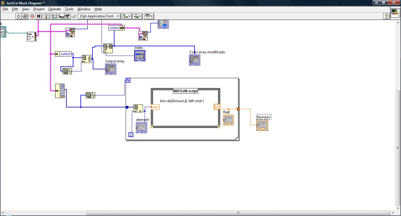
I don't download the .vi because I don't think it will be necessary, in addition, ignore the rest of the image (I just play with image processing like I taught him) and go to the location of the matlab script.
My goal is to represent the image (taken from image data) bit and in the end, it must look like to... a table of 8 columns and all the lines she might need (can't see all of the lines of course) so it will look like a matrix.
For example, it should look a bit like this on the user Panel
| 1. 0 | 1. 1. 0 | 1. 0 | 1. (first 8 bit value)| 1. 0 | 1. 1. 1. 0 | 1. 0 | (8-bit second value)
etc...
So for that, I use the matlab de2bi function and the release of this part is where my problem is, im putting out 8 columns representing each number comes from the image and well, im confused as to what is going out of the matlab function and the loop, as you can see in the picture I have uploaded, I put a flag in the output of 'bin '. , was automatically called Real, inside the loop and the other digital, outdoors, also, I disabled the index of the tunnel in this output. (if I activate the index, it comes out as a table)
I thought that Real and Numeric to be showing the same thing, but when I run it, which doesn't seem to be the case, you Real shows the 1 and 0 (I guess it shows the 8 bits because it shows figures but I saw in the matlab command window and there are 8 bits stored in 'bin') and digital remains just at 0 its almost as if nothing were happening out of the loop, and because I'm not sure what it is falling I can't really find a way to show the bits as in the example, I said before.
Read the help of de2bi, it is said that his exit is a matrix if the input is a vector, but I don't think it's a vector since due to the loop, it takes value by value, then it must go to the default (in binary) value too...
Thanks for the help in advance, in addition, whether something else to better understand my problem please say so and I will do my best to make it easier to understand.
I don't know why you're so obsessed on matlab, LabVIEW can do all this much simpler directly. Here's a possible solution. (LabVIEW 8.5. For other possible outputs you could reverse the Boolean array, so modify them.).

(Your main mistake under matlab is that your output of matlab is defined as a scalar value, then it should be a vector. Your tunnel to exit of the matlab node has the wrong data type.)
-
I only need a port of each line for the use of the PFI and want to use the rest for the digital I/o. Before you complete the design of the circuit and test it myself, I would like to check it out. I can't find the answer in the textbooks, either.
Thank you
Ben
Hello Ben,
If you use all the PFI lines you can use the rest as DI/O. PFI0, 1, 2, 3, 8, 9, 10, 11 are entered digital and PFI 4,5,6,7,12,13,14,15 outputs digital. Another technique you can use is to create a spot on the measurement and Automation Explorer, if it allows you to create it, then it is possible.
Best regards
-
Generating analog output signals 4 with different frequencies
Hi all
I was trying to say to generate 4 different signals at different frequencies
1. first waveform is a sine wave with 5000 Hz,
2. other with 8000Hz,
3. third, one is a square with 25 Hz waveform and
4. fourth one with triangular waveform 50 Hz
all waveforms must be generated simultanoeusly.
I tried to generate with the task unique analog output and sample clock (clock rate is 100000). Cross in scope that I see only 5000 and 8000 Hz we generated correctly and the rest two waveforms show the incorrect frequency.
I guess that's due to the frequency of high clock to sample for more low frequencies for ex 25 Hz and 50 Hz. If I reduce the clock rate to get the lower frequencies properly so I can't generate frequencies higher correctly. (there's a clsh between frequencies and the clock frequency)
Is it possible to use DAQ board master sample clock and its magnitude downward revision (everywhere where it is necessary for each waveform separately) to generate all the signals at different frequencies at the same time in a single task?
-
Headers to the output spreadsheet?
Hi all. I am quite new to LabVIEW and want to headers for my spreadsheet to exit. I made a table 1 d of channels with appropriate titles. I have difficulties to get the data I want and the headers to be included in the output file. Another task, I want to be able to do is to be able to replace only the data in the case where I want to put in a specific set of values. For example, I have 12 columns that have headers, but what if I only want to view the data for only some of the columns and leave the rest blank, but retain the headers show? I am not able to join the code.
Thank you.
Szklanam wrote:
Hi all. I am quite new to LabVIEW and want to headers for my spreadsheet to exit. I made a table 1 d of channels with appropriate titles. I have difficulties to get the data I want and the headers to be included in the output file.
If you show us your code how do we tell you what you're doing wrong? We are not mind readers. The classic way to do this is to call writing to the spreadsheet file and pass it the table 1 d of channels and then call it with the data that you intend to write (for example, your 2D table). Of course, it will be with the input value "append" true.
Another task, I want to be able to do is to be able to replace only the data in the case where I want to put in a specific set of values. For example, I have 12 columns that have headers, but what if I only want to view the data for only some of the columns and leave the rest blank, but retain the headers show? I am not able to join the code.
This seems to be the same question you have to ask: http://forums.ni.com/t5/LabVIEW/Is-there-a-way-to-select-a-certain-box-of-elements-from-a-csv/m-p/19... If this is the case, please keep your discussion in this thread. If this isn't the case, please explain how it is different.
-
Is it possible to limit the output of a multi-turn encoder to match a single round?
I use a Heidenhain encoder with an EIB Heidenhain 741. The 741 takes EnDat signals and converts them. I use a program called LabView of Heidenhain poll Positions. The encoder outputs are incremental and absolute. The outputs take into account after a revolution and I would go back to 0. The program uses a table 1 d with quad 64-bit for the absolute value and an array of 1 d of 16-bit value for the incremental values. I'm trying to convert them into degrees. I have done this except when it reaches 360 that the count is not 0. Is there a way to count position back to 0 when the number of bits is done? Or y at - it a way to make the degrees back to 0? The degrees was taken out by taking the (Position/((2^26)/360)) which is Position/186413.51.
This is my first large LabView project I hope this is enough information.
Use the function Quotient & rest on the digital palette. Divide by 360. The output remains will always be in the range 0-359.
Lynn
-
Outputs produced by the analog input job Retrig delay counter
Hi all!
First of all, I want to thank everyone on this forum who take the time to answer the questions, this forum has been invaluable to me. I have a question about delays in adjustment to the pulse output of a counter, like what is described here. My question is related to another, asked hereon the trigger of an analog signal and producing a pulse for each triggered event. I have this job and can be seen in the attached vi. Basically, now I'm able to produce a TTL pulse whenever my analog signal passes a predetermined threshold. I have also documented the vi to my best understanding, if I have something wrong in the documentation, please let me know.
In any case, now that I have a pulse at each outbreak, I would like to be able to adjust the delay of events so that the pulse is not produced until the period n/20 (n = 0, 1, 2,... (19) what I expect to see is a similar pulse train in 'fig. 2' in the article, where the white pulse is the counter pulse, and the pulse red would be the same as my analog signal. So, for example, if I had a 281Hz signal, I want to produce a single pulse with a width defined by the user whenever my signal crosses a threshold (it's zero delay: 0/20); This part may be made using the vi attached to this subject. Now I want to delay this impulse as to each trigger event, a pulse is not produced until 1/20 of the period, or 0,000178 seconds after the trigger.
Looking at my vi, I think that if I change the output channel of the meter to 'CO Pulse Time' and then set the respective initial delay, time and little time, I can get delayed impulses mentioned in the article. Correct me if I'm wrong, but I think that basically 'big time' controls the pulse width. 'initial period' is what controls how long to wait after the first trigger event is reached, before generating a pulse, but this applies only to the first impulse and not the rest; and finally 'small time' is the time to wait before the next pulse is created.
Earlier today, when I use the CO Pulse Time option, it seemed to work properly for me to a certain degree. At low frequencies the impulses seem to trigger to each event when the pulse width is set at 2.5% of the period. When I tested at 281 Hz with a pulse width, 'big time' of 0,000089 sec and without anything wired for the 'initial delay' or 'small time', the impulses seem to ignore systematically each triggers 2... that tells me that something is wrong in my settings, rather than problems with the sample clock. So I decided to connect '0' to 'small time', but then I got an error message indicating that some time may be less than a value (I forgot what the error message). So I concluded that I must not understand what these terms mean.
Sorry for the long explanation, but I really need help with this. So let's say that the first set of data, I want to acquire is at zero delay, such as pulses are generated at each triggering event like how I have my VI now; so, for the next set of data I want pulses to generate 0,000178 seconds after the trigger threshold; so, for the data set third, I want to pulses to generate 0,000356 seconds after the trigger threshold; and so on... How should I do for this? Thank you very much!
Hello!
Please post on the Forums OR! I think the main issue here is that you are sampling not fast enough to catch all of your high. So you set your high dry 0,000089. You will need to substantially increase the frequency of sampling in order to catch all these. Something around 25 k should do the trick.
To the extent where using the time counter Pulse, you're totally on track. I think that the use that the delay will do the job.
I hope this helps! Let me know!

Maybe you are looking for
-
No dear network after the classification of windows 8
Hi I down graded to windows 8 for windows 7 now I can't get a network dear to my
-
Limit the visibility of music to the songs offline only?
I use iPhone through my car stereo as a source of music. I could browse and select music stored on the iPhone via the interface of the car. I now use the Apple music. I don't listen to music through mobile data. Instead I sync/download albums selecte
-
Cyber-shot DSC-P100 pic view very blue sky
My camera is 10 years (Cyber-shot DSC-P100 and until that time, no problem.) Problem: When you try to view the photos from the memory card or take those pictures become almost 'ghostly' very light blue or as an old "negative." I bought a new batttery
-
I want to change my msn password how to do it please
I want to change my password how to do it please
-
I use Windows Mail to my mail house for years without any problem (via Cox). Without change of setting and unexpectedly, I get security windows pop-up asking username and password (needed never prior) followed by this error message: account: 'House