Over the range on USB-6008?
Dear jury,
I wonder if an alternating signal operating at the limit of the range selected on the 6008 have on beach? Is the limit of the range a dc value; or is it over the range capabliliy built in AC RMS measures? The manual is not clear on this. Someone at - he delt with it?
Thank you very much!
Mike
Mike,
the 6008 is not a method of coupling of special entry. Therefore, the given maximum scope is a DC value.
So if you select 5V as maximum range and have a sinusoidal signal with Vp = 2V and 4V offset, you will cut the positiv to 5V wave.
hope this helps,
Norbert
Tags: NI Software
Similar Questions
-
I am not able to install driver of mx NIDAQ (for the use of USB-6008) in my laptop,... well NIDAQ902f0 want to give any suggestion...
 Following message comes when I run the Setup... (installation program downloaded from the website OR..)
Runtime error:
This application has requested to terminate in an unusual way.
Please contact the application support is more information.
Title of the dialog box is "Microsoft Visual C++ runtime library"
Is the same when NIDAQmx 7.5 is tried to install from the CD that came with the USB-6008.
-
RELAY CONTROL WITH THE HELP OF USB-6008
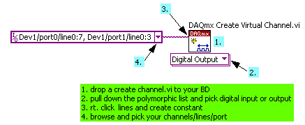
Hi all I'm new to labview, I want to control the relay using USB-6008. could someone help me find valuable solution, because this is my final project mechanical engg. I need the electrical diagram and whether it is digital command also mention details of ports/lines I have to connect.
In this, I joined the relay diagram, in which I have to just to magnetize this nucleus to attract this soft iron. so I need to do ON and OFF. Please guide me and thanks in advance too.
-
Chip exchanged on the issue of USB-6008
I have a USB-6008 data acquisition that went wrong in a set-up. The MCU was getting very hot while it is plugged (I had a ground problem that it fried). I ordered a new microcontroller and succeeded him, now he does not become hot at all when it is plugged in but I need for the flash I think. The argument of doing nothing, the indicator light is not flashing and the computer does not even recognize whether he has a connected device if he acknowledges.
Has anyone here done a repair like this?
Where can I get the software to Flash the chip and can be done on my site?
Thank you all,
Hi ChillyWilly,
You should contact the Customer Service and seek to return the unit. If it is within 30 days of the purchase, this should not be a problem and would be much easier to try to flash the device yourself. You will need the serial number of the device when you call. Hope this helps!
-
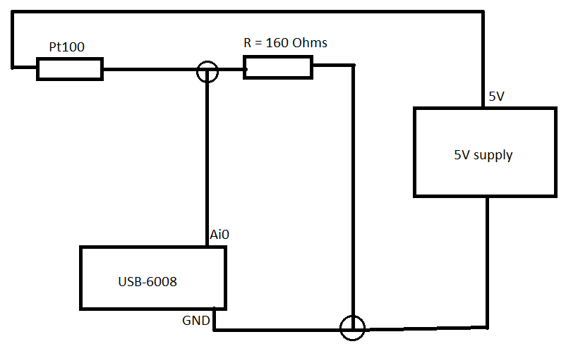
Pt100 (USB-6008) configuration problems
Hello
I'm using the hardware DAQ USB-6008 (I know that's not accurate and all) and I use the Pt100 (QAP2010, click for plug technique).
I connected it like this.
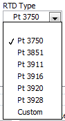
Now in LabVIEW, these are the only options (DAQmx new task-> acquire->-> RTD temperature signals).
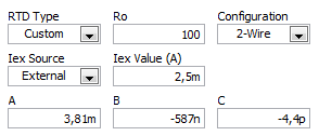
If I choose for custom settings, I get these options (I don't know what variables that is).
I use a small greenhouse where I need to measure the temperature and humidity and control environment (by using a fan to cool the cartridges to greenhouse and heat to heat).
My goal is to read the temperature using a graph on the front panel.
Can someone help me how configure/choose the right options? If you need more information I'll provide them as soon as possible!
A quick search for RTD class B shows the precision and the coefficient. As Fan Ravens stressed resistance according to the temperature is plotted in the data sheet. To control the temperature in greenhouse, a simple calculation of the slope of this graph is not good enough.
Note that the USB-6008 case limited an active player on the outputs analog and it controls only the voltage. So you will need at least one external resistor and possibly and external power to excite the RTD. These options that you have linked is not applicable to the USB-6008, which is a very simple device. You should perhaps simply to measure the voltage and calculate first resistance, then the temperature.
Lynn
-
Get incremental counter/sound to work along side with action with usb-6008 with labview tia sal22
Get incremental counter/sound to work along the coast with usb-6008 with labview tia sal22
Hi all
I can get this vi to work if they are distinct from the vi but I can't join them together
Example of my error:
If buffers are set to 0 the freq counter increment works, but no sound
If the buffers are set to 1 the audio works fine but is not increment the Freq counter
If the buffers are attached to more 1 clicks and pops are comingThat's what I'm doing:
(1) have the frequency of increment of my internal sound card to a certain level as .01hz a second until he gets to 20 000 hz(2) use my device usb-6008 daq, which is connected to the same machine to measure the voltage at the same time. (I am in a position very low voltages between 1-5volts)
(3) output to a worksheet text file which will show you:
time in seconds, frequency, voltage
0,400.01,21,400.02,2.5
2,400.03,1
I'm a bit confused about how connect the increment and the audio during the measurements with the usb-6008 housing on the same machine
at the same time and in the same VI.Anyone have any ideas? I'm using labview 8.5
TIA sal22Ha ha you have been deceived by a dynamic thread. Insert a convert from Dynamic Data Express VI (Palette to own: Signal handling screw Express) between the daq read and build the array function. Then it won't work. Now the value in the dynamic data is only converted to a numeric value
-
Hello world!
I have a project with USB 6008. I want to count impulses (for special features: count the pulses of the encoder) use USB 6008. I wirite with DAQmx to test a simple. But it do ' t run. Please see and help me to do this exercise. I just borrowed 6008 USB so I don't have any experience with USB 6008. Thank you! It's funny.
Looking at the PFI0 manual (pin 29) is correct and I don't see anything wrong with the code and example should work. I have a M-series card, not a 6008 and it works for me. This error code is meaningless if. Are you sure it's the number?
-
DAQ USB-6008 will be able to power and record voltage for UMS T5 blood pressure at the same time?
I would use my NI USB-6008 to power my blood pressure monitor UMS T5 (http://www.ums-muc.de/en/products/tensiometer/t5.html) but also to take readings of it, but I don't know if it's possible to do it properly. The power supply for the instrument can be as low as 5V, I can easily get the dedicated + 5V channel. I'm able to feed the instrument and connect it to an analog input on the 6008 and measure a voltage in differential mode. However, when you read the documentation of support for the instrument, I find the following:
"Potential pitfalls of data acquisition: the pressure transducer is configured in a full Wheatstone bridge, the input voltage and mV signal output can be connected to the same reference (mass)." Therefore, the mV output signal can be measured using a differential voltage measurement. Therefore, do not make an asymmetric measure of pressure transducer mV output. "(http://www.decagon.com/assets/Uploads/MeasuringUMSTensiometerswithnon-UMSControlandDataAcquisitionSystems.pdf)
My understanding is that the 6008 can take a differential measure if I attach the signal '+' and the signal "-" to the analog inputs of positive and negative terminals. However, it seems that all the ports of ground on the 6008 are grounded to the same reference, which would make my measure of invalid tension according to the above paragraph. So my real question is: if I try to record the voltage with one of the analog inputs on the 6008 in this way, is the valid measurement? Or I need to find a separate power supply, with a different reference field to ensure that the measure is accurate?
The technical details of this device is very poor. The manual is not much better. Companies that want to sell scientific equipment should publish decent cards or get out of business.
In section 3.4.3 General requirements the device is described as a "bridge not amplified circuit. This information along with the impedance of the bridge should be in the specifications, because it is essential to apply the device under any circumstances other than the nominal behavior in 10.6 V.
The answer to your question is:
You can use it with the box USB-6008. The 5 V supply will result in output voltages a little less than half (5/10.6) the voltage specified in nominal conditions. You can use the differential input mode on the box USB-6008. The absolute input voltages will be approximately 2.5 V with the 5 V power supply. This voltage is in the range of the aircraft. The differences are likely to be less than 100 mV. The resolution of the USB-6008 on the + /-1 V is located about 0.5 mV so your resolution of pressure will be about 1% of full scale. The voltage input impedance and termination of the USB-6008 will present a few errors. These can be in the order of 5 to 10%. I can't predict much better without the missing bridge impedance specification. These errors should be relatively constant and systematic. A calibration of the whole system - sensor and together hardware DAQ should allow you to compensate for a large part of this error.
Lynn
-
Beyond the limits of voltage on USB 6008?
I use a USB-6008 to measure analog differential in the range of 3 to 5.3 V. I chose this range, because outside this range, I'm not interested in what the tension is, knowing that his "on the rail", but to aid resolution of the ADC in this range.
So for a signal of ~0.05 supply V, I expected to read 3V, telling me that the voltage is lower than 3V, but again it returns 0.05v?
As it was unexpected for me, could someone please explain what can / should I expect of my USB6008 of the responsed to the signals that are the limits? Is there an effect of "rollover"? Should you return the value to the limit? Depends on how far the limit is?
Thanks for your help!
Entry level do not think that way. You specify the range is that you wait for the signal and the DAQmx driver will set the most appropriate range that the device supports. The actual ranges are indicated in the guide. In your case, because you specify a max of 5.3, the device would be defined the +/-10 volts range.
-
Want a ramp of output voltage over time and measure input 2 analog USB-6008
Hello
I want to produce an analog voltage output signal that increases over time with a certain slope, which I'll send in a potentiostat and at the same time I want to read voltage and current (both are represented by a voltage signal) that I want to open a session and ultimately draw from each other. To do this, I have a DAQ USB-6008 system at my disposal.
Creation of the analogue output with a linear ramp signal I was possible using a while loop and a delay time (see attachment). Important here is that I can put the slope of the linear ramp (for example, 10mV/s) and size level to make a smooth inclement. However when I want to measure an analog input signal he's going poorly.
To reduce noise from the influences I want for example to measure 10 values for example within 0.1 second and he averaged (this gives reading should be equal or faster then the wrong caused by the slope and the linear ramp step size.) Example: a slope of 10 mV/s is set with a 10 step size. Each 0.1 s analog output signal amounts to 1 mV. Then I want to read the analog input in this 0.1 s 10 values)
Because I use a timer to create the linear ramp and the analog input is in the same loop, the delay time also affects the analog input and I get an error every time. Separately, in different VI-programs (analog input and output) they work fine but not combined. I searched this forum to find a way to create the ramp in a different way, but because I'm not an experienced labview user I can't find another way.
To book it now a bit more complicated I said I want to measure 2 input analog (one for the voltage of the potentiostat) signals and one for the current (also represented by a voltage signal) and they should be measured more quickly then the bad of the analog signal. I have not yet started with because I couldn't read on channel work.
I hope someone can help me with this problem
An array of index. You want to index the columns for a single channel.
-
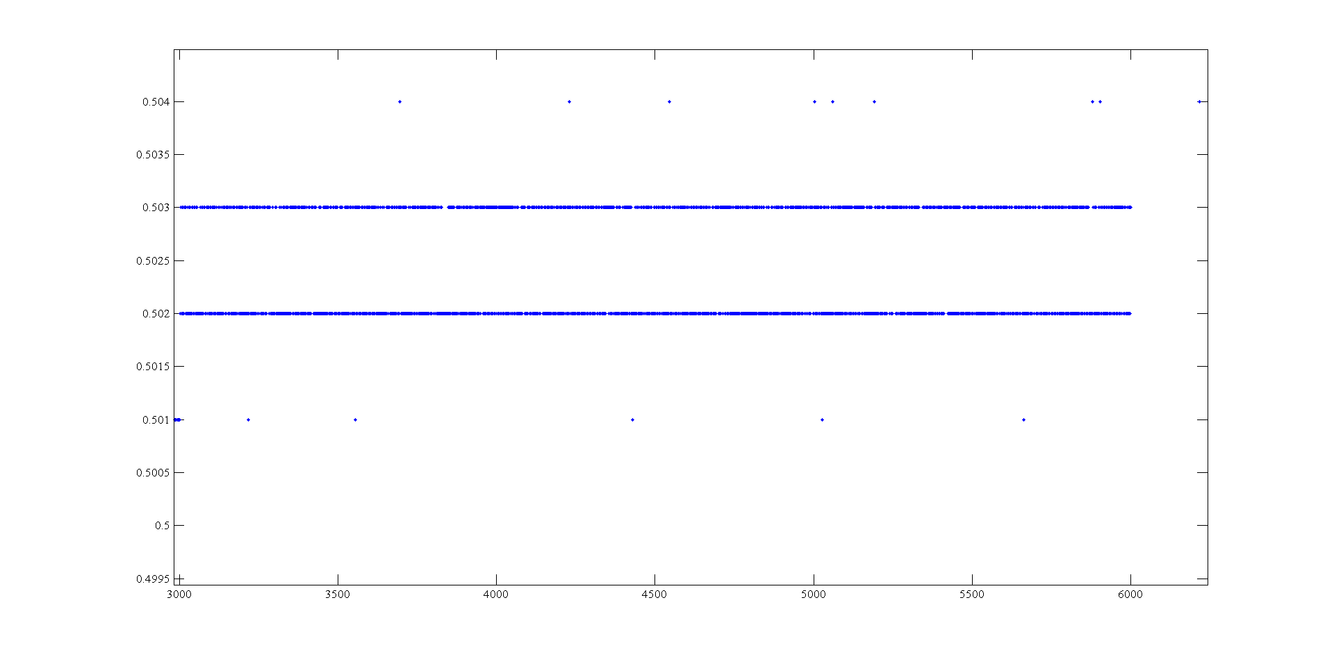
Measurement of voltage USB 6008 ranging from 1mV
Hi, I'm doing a supply at an angle for an amplifier using the USB-6008. The ranges I look are - 0.5 to 0.5 V and 0.5 to 2.5 V. To generate negative tensions, I use the + 2, 5V for a reading of differential voltage output as a 'ground '. Voltage measures have a delay that varies with the voltage, given this by drawing these variations and set the output to data acquisition there is still a 'noise' of +/-1 mv so that it is clear from this parcel of tension against the sample number:
It seems that at some point the values are being rounded up to the nearest millivolt. I need to get to a resolution of 0.5 mV for my device, it will be possible with the USB-6008?
The AO USB-600 x has a range from 0 to + 5 V and the 12-bit resolution. 5/4096 = 1.22 mV. Absolute precision is 7 mV typical and 36.4 mV maximum full scale. The noise of the AO is not specified.
If you measure the results with THE USB-6008, you have at least 0.5 mV, similar resolution system noise and absolute accuracy of 2.5 mV or more.
It's probably as good as you will get with the box USB-6008.
Lynn
-
I can read two-channel USB-6008 using THE Signal Express?
Hello world!!
Is possible to read the two analog inputs at the same time?
Example: Using Signal Express, I need to read the (channel 0) analog input and analog input (channel 1) at the same time.
I try this but, the signal on purpose gives me an error message saying that I can't read several channels at the same time using the USB-6008.
Is this true?
Thank you
Ivo João
André,
Grato definition of pela.
SUA ajuda muito util faith.
SDS,
Ivo João
-
E/s digital USB-6008 changes when the system starts
I was intending to use the USB-6008 housing in a critical application in which the digital I/o lines are used to trigger relays. The relay should activate when I ask them programmatically. Otherwise, they must remain open. The problem is that during a reboot of the operating system, the e/s digital USB-6008 go up and down several times - opening and closing my relay. It is not acceptable for my application.
Is it possible to prevent the lines to reach logical high except if ordered to do so?
There is no way to set the startup on the 6008 States.
As the system USB boot devices and turns on power to the computer and off the power to the USB ports, on the DIO lines go up and down several times.
You will need to put a logic of material extra, just after data acquisition to ensure that potentially dangerous output combinations cannot affect the relay and the elements they control.
-
Cannot read the digital channels as physical on USB 6008
Hello world
Sorry for maybe a stupid question, but I'm stuck and can not find the solution.
I can't read my outputs digital my USB-6008 as physical channels but only as global chains. Is this normal? What can I do to work around this problem?
Thank you, any help is very appreciated.
-
I have a USB-6008, I read an entry on the OID.
I want this 1 report when the line has a present 5v and 0 for something else.
When I don't have anything on the lines. It reads 1
How configure it to read 0 when nothing is connected?
Also how I re this in c#
Thank you
Hello ashitakaLax,
The USB-6008 housing has an internal pull-up resistance to 5V (according to page 22 of the User Guide and specifications) that pulls the line to 5V when nothing is connected.
In order to change this, you can add an external resistance of menu drop down to make the output to the earth when it is disconnected, if your device should get power to fuel the high line.
Kind regards
Maybe you are looking for
-
I lost all my tools, including the address bar & buttons - nothing to click on restore
I lost all the toolbars, including the address bar, the buttons,the only thing it is the blue band that says mozilla firefox, nothing to click on restore I opened firefox User Agent Mozilla/4.0 (compatible; INTERNET EXPLORER 6.0; Windows NT 5.1; SV1
-
Satellite Pro A200GE and WXP - can I use the PSAE7 drivers or it won't work?
The performance of Vista business makes me crazy, I need to go back to XP + sv pack 2.If I format my machine (A200GE) and install XP. can I use the drivers for the PSAE7? (or that the A200GE is PSAE7E this solution will not work?) Also do I need to c
-
LabView Run - Time Engine 2009 installation failure
Hello I have problem to install Labview Run - Time Engine 2009. This error occurs: Die Installation von NI VC2008MSMs x 86 ist auf Grund of the following Fehlers fehlgeschlagen. Auf den Windows-Installationsdienst konnte nicht rarely werden. Die kann
-
Perforce Workspace and LabVIEW
Hello I take more than one job where I use an existing computer that has been configured with Perforce for Source control of LabVIEW. I use the same local workspace as my predecessor who is simple, the c drive. When I create a new VI and add it to pe
-
Ultimacy Windows 7 RTM 6.1.7600.16385 x 86 + windows live is good until the help live movie maker a serious error error Log:Signature of the problem:Problem event name: APPCRASHApplication name: MovieMaker.ExeApplication version: 14.0.8091.730Applica