PCI-6115 counter 0, 1 output current capability?
Can charges of 50 ohm PCI-6115 player with the counter 0 or 1 meter outputs? The specification data sheet had no information on that.
Hi src42,
The data sheet indicates the maximum amount of current that can come from the digital lines to 13 my @ 4.35V. This unfortunately not sufficient to drive a 50 ohm load.
Best regards
Tags: NI Hardware
Similar Questions
-
the pci-6238 digital output current
Hello, I referred to the NI 6238/6239 specifications, but I've not seen this specification.
I wonder if the maximum output current is the same as the current (9mA) of entry?You can check this link for the information you need:
http://sine.NI.com/NIPs/CDs/view/p/lang/en/NID/202503 -
PCI-6115: no error is raised when a buffer overrun occurs
Hello
We use a PCI-6115 continuous acquisition to 10 MHz mode.
We read samples in blocks of 10e7 samples (i.e., by blocks of a second). Before you read the samples using the 'Daqmx Read analog 2D I16 NChan NSamp' VI, we check if the samples are available using the property "Daqmx Read--> status--> samples available by channel":
- If 10e7 samples are available, we call the 'Daqmx Read analog 2D I16 NChan NSamp' VI with timeout =-1.
- If not, we wait a few milliseconds and retry.
Unfortunately, we didn't intercept errors related to buffer overflows. I mean, I did some tests. And when a buffer overrun occurs, instead of getting an error related to a buffer overrun, the property "Daqmx Read--> status--> samples available through" simply returns 0 indefinitely.
This behavior is not what we want. We want something solid to detect buffer overruns. Is there a VI or property to check if a buffer overflow has occurred?
Instead of testing ourselves if samples are available, is it best to let the 'Daqmx Read analog 2D I16 NChan NSamp' VI do with timeout =-1 directly?
Thank you
Kind regards.
xRed,
I don't have the equipment to test this at the moment, but I think DAQmx's task Done.vi go do what you want. The problem with the help of samples available by channel property is that it is valid to call it when the task is technically done (error, or after the acquisition of all of the samples in a task finished) to determine how many samples can be read. As the error you have is a buffer overrun, there is no samples that can be read safely, the query returns 0. In your case of error, I expect that DAQmx is task Done.vi would return True for 'task performed?' output and the error you code were expected since the release of "error".
Hope this helps,
Dan -
How to determine the amount of memory was my pci-6115?
How to determine the amount of memory was my pci-6115?
I see two beaches of memory OR max.
My PCI-6115 there 32 or 64 MB memory?
Range of memory between 1: FE9F7000-FE9F7FFF
Range of memory between 2: FE9F7800-FE9F8FFF
It's an old part number for the Board 32 MB.
-Christina
-
Effect of the variation of the intensity of the LEDS on the Photodiode output current
Hello
I just started today to use the multisim and want to analyze how the intensity of the LED (LED_ir in multisim) is performing the Photodiode (TEMD1000 in multisim) output current. How to adjust the intensity of the LED and check the corresponding output on the photodetector on the oscilloscope.
I just built the attached LED design and don't know how to design the model for the foregoing analysis.
Could someone help me with this.
Thanks in advance.
Hello
Multisim works mainly with voltage and current, and whenever you need to represent the other phonominal naturual have a voltage or current source control. For a TEMD100, you must connect to a source of voltage up to ternimal light represents the input light.
-
problem of analog with PCI-6115 and BNC-2110
Hi, I have an acquisition of data PCI-6115 and BCN-2110 connector card I want to measure continuous analog voltage. Now I can permanently measure the intensity of light laser of photodiodes through channel 1 and get the reference through the 0. Then I can get the harmonic signals by the multichannel lock - DAQmx.vi. However, I also want to simultaneously detect another analog signal in channel of gold voltage 2. The problem is: Channel 2 voltage range is approximately 0.3 mV to 6 mV which is significantly lower than the other channel 2 (0 - 10V), how could put different prescription by channel continuously and simultaneously acquire all data?
I found that Dennis Knutson has provided the solution a year ago, which is listed below:
In the solution, it should be arrays of strings, lines, patterns, but I do not know how to apply it to my case. Is there a suggestion or another solution?
Thank you very much!
You have the autoindexed exit task and is not correct. Try the code below.

-
Digital output crosstalk PCI-6115
I am trying to create 8-bit specified output signals by various software-created the waveforms that are repeated indefinitely. A typical example of this waveform is a sine wave of 280 Hz. The configuration is as follows: (1) Ctr0InternalOutput used as the clock source. (2) clock frequency is 50 kHz. (3) the connections established with the connection of the terminal of the wire SCB-68 box.
I use an oscilloscope Tek MSO 4104 to 1 GHz (4 analog inputs, 16 DIO - 8 inputs are used) to monitor the digital signals of the 6115, either with analogue or digital scope entries. I was able to generate signals, but the problem I see is a systematic corruption of levels individual bit by other bits. For example, the MSB (that changes less often) shows HI-LO or LO-HI transient when you use the input OID field. With analog inputs range, this is demonstrated by spikes of noise of low-amplitude on the line given. All these transients are synchronous with the edges of the transition from other signals.
My guess is that it is some kind of problem termination or loop Earth with DIO 6115 connections. I first tried using a simple tablecloth (main 8 more on the ground) cable. I got some improvement by replacing it with the individual lines of 50 ohm RG-174/U, linking each coaxial cable to the digital earth nearest ground terminal. Then I put at the end of the output of each line of coaxial cable with 100kOhm and 100pF (parallel) to his shield to the ground. These measures improved the signals, but do not eliminate the problem. I'm looking for advice on how best to configure the connections of DIO or condition the signals.
I found myself in the land of P0, P6 and P7. This reduces crosstalk to acceptable levels. I do not pretend this is a unique solution, but the grounded all the shields of coax has not produced as net results. I found online OR hard to find, and inadequate documentation to discuss these issues.
-
Using the NI USB-6009 case to generate a 12VDC output and output current of 300mA
Hello
I use the OR-USB-6009 my power supply for a 12VDC with drive current of 300 solenoid my. Initially, I used a non reverse Op-amp circuit and Inverter circuit operational amplifier to get the + 12V and - 12V output but I could not get the current I required. Should I use a transistor?
Please find attached photos. Any input would be appreciated.
Thank you
Adam
Well, really depend on your piercing circuit. But I used most systems use the transistor to set the voltage of the device to 0V. So when your DIO is high, the output is actually 0V (low). So using a converter chip, your release of the DIO will be sort of the output circuit. If you get the right IC, then the inverter will give you also a few extra current to drive your transistor.
-
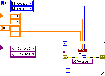
Streaming AO of manipulated copy of AI: PCI-6115
I would like to release an analog output of a manipulated copy of an analog input, but I can't seem to get anywhere with the available examples. It could well be an impossible task with DAQmx.
Thanks John, I'm capable of running late; This work certainly if I actually had a stream of data. I have described my system incorrectly. There are synchronization problems that will not allow a delay in the AI and AO without errors. However, it works as expected, make me wish that I had a continuous application to use it on. No worries, I have a solution that will still be able to manipulate data in real-time using a channel AO and some hardware.
If there is a solution to this problem in real time, let me know.
-
read the output of a path of analog output current voltage
In DAQmx if you are unsure of the status of a digital output port, you can take a reading on this subject. When I try this on an analog output, I get an error. Is it possible to query the status of the output of an analog output? I realize that I could follow the State with a variable, but a direct reading would be really handy.
Hello, GIS.
There is no way to read the output in the AO modules without wiring physically the signal to a module to HAVE. You are able to use a variable to read the current value of the output, as you mentioned earlier.
Channels AO multifunction boards, however, can be read through tasks of entry by rounting in-house channel to read ao vs aoground.
Lisa
-
acquire the voltage output of a channel of analog output current
I'm controlling a HV configuration rather sensitive analog output voltages. Is there an easy way to read the voltage level which is currently awarded by an analog output?
Hello
If you set your subVIs different voltages, you can be sure that the voltage you set in these screws are similar to tensions, you have to your output PIN. For example, you could write the value you give to the output in a variable and read this variable in you main VI.
Kind regards
Peter
-
Different voltages of output current transducer
This will be my first experience on the use of daq cards and transducers so forgive if I ask stupid questions and any essential info is appreciated related to topic. I'll use the NI USB 6128 daq card. Range of analog input is ± 10 V, ± 5 V, ±1 V ± 0,2 v There are different output voltages of sensor current as; 1.65V ± 0.833V, 2.5V±0.625V, ±10V, 4Vrms, 2.5V±0.5V (these are the values of the LEM)... ±10V seems most appropriate, but they tend to be expensive. What happens if I use a transducer which has voltage output 4Vrms? I'll lose precision, if yes how much?
Secondly, I have solar panels and I need to measure the temperature at the surface. What type of sensor will be more suited and how to read temporary data in labview. I know 6128 USB can not see thermocouple or rtd and their modules are expensive is there another way to measure the temperature and read values in labview.
Thank you
Hey, Sojo,.
Yes, you still have the same number of voltage level because the resolution of a/d converters is the same. 16 bit means 65536.
These 65536 steps will extend your range by the gain of the internal amplifiers. So, if you set a smaller measuring range you get a higher resolution. For example is the smallest step 3.05mV with +/-10V Beach and 1.22mV using the +/-4V range.
And you can measure RTD if you use an external voltage, and you also can measure Pt100 and Thermocouples without additional hardware. However, using the appropriate signal conditioning hardware is always preferable in terms of accuracy.
I suggest you to contact your local office of NEITHER and leads to an internal sale representiv that can give you the best suggestion of material for your application.
Christian
-
REUNITIALISATION CARD PCI-6624 COUNTER PROBLEM
Hello
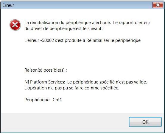
I have an app with maps CAN, digital, analog and media cards. So as soon as I have my application error (error CAN or other) which forces me to stop it, I have my card PCI-6624 counters who don't get réunitialisent not and so I have the following error at the next launch of my application:
I point out that I have this error since I updated my app (LabVIEW 8.5-online LabVIEW 2011) and plug-in DAQ 9.3.5.
I edited my code and checked that I was doing well clear United Nations of my tasks and a reunitialisation of my media card pour itself out of my app in case error.
I can even stop and close the application and once in MAX can't réunitialiser media cards after a crash, I always have to turn them off and turn them back on in the peripheries windows or restart my computer.
Please inform me if you had already encountered a problem like this or help me solve this problem if you have an ideas for me. Thank you in advance.
Hello Jr_Marlet,
This problem is known and has been resolved with the release of DAQmx 9.4. I therefore invite you to retrieve this version (or even 9.5) on ni.com/download.
Feel free to get back to us if the problem persists.
CDT,
Eric
-
R series: compared to current output output impedance adaptation
Hello
I wonder about the output impedance specified for SMU-782xR and some other adapter module ike l 6581.
The specified output impedance is 50 ohms. To get the best signal integrity, it is imperative to adapt the impedance using a cable (transmission line) with a 0 hm 50 characteristic impedance and impedance of 50 ohm load.
But I don't understand how this is possible, because with a high level of 3.3 v, the output current proposed spindle must be 66 my. The current per output pin max 7821R is 4 my.
This FPGA offer 128 pins, so that the maximum total output current should be of 8.5 A, so 28 w. It's not realistic!
Could someone explain why outputs are 50 ohms?
And how do I adjust the line and the termination of employment?
Thank you and best regards,
Benoit Chantepie
Benedict,
After some thought, the concept of the output impedance is really not applicable outputs logical digital because they spend most of their time in the saturated States and time spent in the transitory States is not usually specified with the exception of the time limits.
What is your purchasing process is I would ignore the specification of output impedance. Watch the voltage and current limits. If those who do not meet your needs, consider external buffers. You can specify the buffer to meet the requirements of your testbed (including protection against defects if necessary) and to meet the specifications of the devices OR.
Lynn
-
How of current analog output more than 2mA
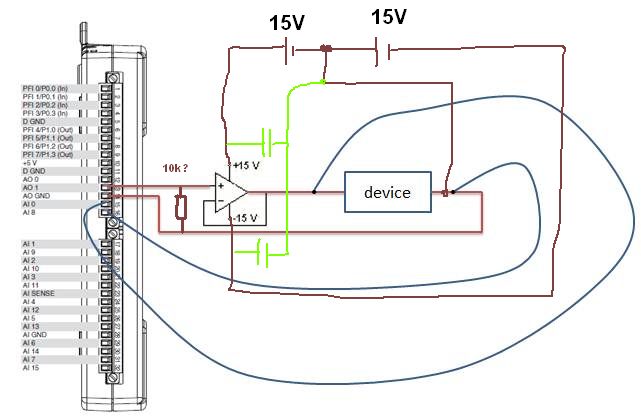
Hi, I have designed a simple PID loop to control the input of a device voltage. My camera has an Ohm resistance. I found that being controlled input voltage may not exceed 0.6V, then I realized that the maximum output current is my 6211 NI DAQ 2mA. But I really need more 2mA (Max is 10mA). I tried to use a voltage follower because it has high impedance imput and low output impedance, but it does not work. Could someone tell me a method to solve the problem?
Thank you.
CJL
100nF caps | with 10µF,.
R optional...
What OP do you currently use?
Without this connection GND current can flow
 so you will stick to 0.6V as without a driver.
Maybe you are looking for
-
ConfigFree is not working properly under Windows XP
Looks like the Configfree does not work as it should on my laptop satellite. I get a ghost of an image icon with Summit, connectivity, profiles and Q-Connect points. I can't do anything with, then icons on the screen. Connectivity doctor doesn't seem
-
Library of updated hp has lost
I am running Windows 7-64 bit, Hp Pavilion p7 = 1258 Desktop PC and can not run the update of HP for the lack of update of library. How can I fix it? I run Assistant HP and updated, but it has not installed the software library for the HP update. I s
-
I 4.41 MB of free space on recovery (d) 14.6 GB, what can I do to get more space?
Hello! When I bought CONNECT, the technician I spoke with told me I was 4.41 MB of free space on recovery (d) 14.6 GB. What can I do to get more space? I need help, please!
-
CheckSUR.exe - problem with Windows Update - 80073712.
Hello, I'm apparently missing these 4 files since my last update, and I'm unable to download anything else. Already tried the fixes posted here, but nothing. I really don't want to reinstall Windows. :( =================================Preparation of
-
Computer is sluggish and delays in responding to orders, sometimes even freezes
computer is sluggish and deadlines to meet orders, sometimes even freezes. He will not obey shutdown command causing abnormal termination in order to restart it. Malware scan negative for the virus.