PCI-6132 redeclenchables
Dear all,
I have a problem with my acquisition of data PCI-6132. I need
to acquire the signal with a finished sample. Data acquisition signal of early acquisition of
Digital edge of the trigger of the beginning, start signal to the spesified collection
quantity of the sample were acquired. Its beginning to collect a finished sample
Yet once when another trigger of early digital dashboard detected.
Therefore,.
I put the attribute trigger digital beginning as retrigerable. But when I
called DAQmxErrChk (DAQmxSetStartTrigRetriggerable (taskHandle, true)), it
who says:
DAQmx error: the specified property is not supported by the device or is not applicable to the task.
Property: DAQmx_StartTrig_RetriggerableTask name: _unnamedTask<0>
State code:-200452
End of the program, press the Enter key to exit
First of all,
I think that the DAQmx_StartTrig_Retriggerable property is not supported by
My DAQ (PCI-6132). But when I read Help reference C-NOR-DAQmx, suite
Well supported by heading device, redeclenchables start is one of OR
PCI-6132 taken in charge the property. Why this error eccur?
My code
is the same as ContAcq-IntClk-DigStart - Retrig.c
Thank youInt32 = 0 error;
TaskHandle taskHandle = 0;
tank errBuff [2048] = {'\0'};/*********************************************/
DAQmx Configure Code
/*********************************************/
DAQmxErrChk (DAQmxCreateTask("",&taskHandle));
DAQmxErrChk (DAQmxCreateAIVoltageChan(taskHandle,"Dev1/ai0","",DAQmx_Val_Cfg_Default,-10.0,10.0,DAQmx_Val_Volts,NULL));
DAQmxErrChk (DAQmxCfgSampClkTiming(taskHandle,"",1000.0,DAQmx_Val_Rising,DAQmx_Val_FiniteSamps,100));
DAQmxErrChk (DAQmxCfgDigEdgeStartTrig(taskHandle,"/Dev1/PFI1",DAQmx_Val_Rising));
DAQmxErrChk (DAQmxSetStartTrigRetriggerable (taskHandle, true));DAQmxErrChk (DAQmxRegisterEveryNSamplesEvent (taskHandle, DAQmx_Val_Acquired_Into_Buffer, 100, 0, EveryNCallback, NULL));
DAQmxErrChk (DAQmxRegisterDoneEvent(taskHandle,0,DoneCallback,));/*********************************************/
Starting code DAQmx
/*********************************************/
DAQmxErrChk (DAQmxStartTask (taskHandle));printf ("absorbent samples continuously. Press Enter to interrupt\n ");
GetChar ();Error:
If (DAQmxFailed (error))
DAQmxGetExtendedErrorInfo (errBuff, 2048);
If (taskHandle! = 0) {}
/*********************************************/
Stop DAQmx code
/*********************************************/
DAQmxStopTask (taskHandle);
DAQmxClearTask (taskHandle);
}
If (DAQmxFailed (error))
printf ("error DAQmx: %s\n",errBuff); ")
You
Hi oktanto,
I simulated the device, but I was not able to run a redeclenchables VI of analog input. It seems that this property is not supported by the 6132. There may be a workaround is possible: you may be interested by the following code example. Although it is a little older, he should probably still work for you
Tags: NI Software
Similar Questions
-
Timing embedded with Daqmx on PCI-6132
Hello
My colleague and I are trying to make a program Labview which starts a timer when the first trigger (sensor) is struck and stop the timer when the second trigger (sensor) is reached in 2012. We currently have a program for her, but this program was not sufficiently precise. Also the current program is using the DAQ assistant, but we would like to replace with daqmx triggering. We have also tried to use the OnboardClock on the PCI-6132, but still could not do the work programme.
Is there anyone who knows how to do this and could explain it?
(In the attachment is the current program)
Thanks in advance,
Tommy van Geest
Hello Tommy.
You can share your current code?
-
My card PCI-6132 at some point began to generate error (code error-50400) during the race. It does not pass to the MAX OR self-test with the same error code. As I see that one of the chips, I think it's a shame. We bought a long time ago, so the warranty has expired. So my question is what it can be caused by? And how can I avoid this in the future? Can it be fixed or I just replaced this card?
I apologize for my previous post, which indicates that this type of behaviour can be expected. I want to clarify that we certainly do not expect these damage with our products during operation in the specifications.
I encourage you to contact OR by phone to set up an RMA for the Board so that it can be repaired and futher diagnostic.
-
The PCI-6132 analog inputs does not
Hello
I have problems to install a PCI-6132 card on one of my computers. I am runing Labview 7.1 and DAQmx 8.6. In MAX, I opened the unit and test panels. The counters are working fine however the analog inputs always give v - 10 (-5 If the a - 5 min) without noise. the same on each channel. I have not connected any termianls and expect to see the noise around zero volts. In addition, the card fails the error calibration auto-200545.
I took an another PCI-6132 of a system works in this computer and had the same problem. So I guess the problem is the configuration of the computer or software. I try to reinstall the DAQmx and labview and the problem has not been corrected.
Nick Wagner
NOAA/ESRL/CSD
(303) 497-3924
-
Laptop crashes when you use PCI-6132 and a box of magma
Hello
I use a laptop with a magmabox (Cardbus connection) to accommodate a card DAQ of NOR-PCI-6132. When I'm data acquisition the laptop freezes sometimes and has to be restarted. Anyone who is familiar with such a problem?
I did not have this problem when the DAQ card is in an office with a regular PCI slot. So, I guess that the problem is related to the magmabox.
Nick Wagner
Hi Nick,
The problem could very well be linked to the magmabox, but before that can be determined, I need more information about your hardware. I already know about the PCI-6132, but I don't know anything about your laptop or magmabox cardbus connection. Can you tell me the manufacturer and the model number of your laptop and the magmabox so I can check their specifications? Thank you.
Best wishes
Wallace F.
-
Hello
I am trying to send a digital signal using a PCI-6259 and concurrently read an analog waveform using a PCI-6132. I tried to look at examples of synchronization but seem to have trouble trigger c using DAQmx Start Trigger (PowerPlay).
Is the 6259 likely to be triggered from a 6132 for DO?
Thanks for any help,
Colin
-
Hello
I use simple vi to acquire the data of 4 analog inputs (photo attached), but I get this error message 200019. I use PCI-6251(16-Bit, 1 MS/s (Multichannel), 1.25. MECH / s (1-channel), 16 inputs analog) card. At lower rates, it will work perfectly, but when I try to acquire samples of 5 M to the sampling frequency of 1 M I get this error. I tried the internal/external clock / ref 10 Mhz clock / and different combinations but problem still presists. Even at a slower rate (900K / 800K) the same thing happens.
Help please,
Sine
Hi Sine,
I'm not surprised that your device will work slightly above the rate in the specifications. Remember, though, that your device has an ADC. As read you through several channels, they must obtain a dial both to the ADC. The reason why that unit has a lower rate specified for the case of using several channels is to give time to this circuit to settle during the passage of the channel on the channel. The ADC itself can operate at the same speed (a little above), which is consistent with the behavior that you saw. Regarding the unit I have recommended, I simply looked at the DPI of the device that you use (16 bits) and the rate / number of channels that you were trying to get data from. If you do not need 16-bit resolution, a cheaper alternative can be the PCI-6132.
To answer your question concerning the size of the buffer. To do this, I think you'll need to use VI lower than the DAQ Assistant. To do this, I recommend one of the two methods. You can view the examples provided with DAQmx (Bar Menu of LabVIEW--> help-> find examples-> hardware input and output-> DAQmx-> Analog measures-> voltage). In this list, I would recommend selecting Ack & chart voltage-Int Clk.vi. The other method is to right click on your DAQ Assistant VI and select generate DAQmx Code. In both cases, you will see lower level DAQmx VI and how they are used to set up a task. To change the size of the buffer, you must insert DAQmx Configure input Buffer.vi before you call on your task. This VI allows you to specify the size of the buffer that DAQmx acquires.
Hope this helps,
Dan
-
Dynamic report having to update each round in PWM
Hi all
I am a newbie of LabVIEW working on the generation of PWM signal. I have to generate a PWM signal such as its ratio of obligation and indeed it should change the pulse width in each cycle based on the values stored in an excel sheet. I downloaded an example of or and try to change it, but not with much success. I use NI PCI-6132 and BNC-2110 in my configuration.
I read some examples on the generation PWM based on the dynamic ratio by manual control using 1.2 but counters have not found something that updates the report obligation to each cycle.
For an example, I enclose you a csv file containing 4 values and ratio to the vi. My goal is to generate 4 pulses with the ratio of stored in the csv file, then stop execution of the program. For starters I keep the frequency 1 Hz. I know that the vi is not correct and I'm working on it, but I thought getting some suggestions at the same time.
Thank you very much for your help.
6132 counters cannot do what you ask. Using this material, you must generate the appropriate digital output table based on desired time and use a digital output buffer task:
STC3 based on recent hardware components (e.g. PCIe-6320) is able to output meter in the buffer:
There are some drawbacks to the use of the method of digital output which can or may not be a problem for your application:
1 it requires a much larger buffer (1 byte per example compared to 8 bytes per period). If you need high temporal resolution and are in need of a long sequence of pulse output you may not be able to write the entire buffer at a time.
2. more data needs to be listened to on the bus (also 1 byte for example compared to 8 bytes per period). Could be a problem if you are running at the same time as other streaming applications.
3. less time resolution (10 MHz output frequency max on the 6132 compared to 100 MHz output meter timebase on a series of X).
Best regards
-
filtering of noise over 200 kHz
Hello!
I'm recording ultrasonic vocalizations of rat at 1 ms/s using an acquisition of data PCI-6132. One of my colleagues is ultrasound analysis of data from the records and asked me to apply a filter on the signal, as it is registered. He asked the specifications was to "filter noise on 200kHs, with a steep slope. I have no training in hearing analysis, so I have no idea what he's talking about, or how to impliment it. Can anyone interpret this and help me understand this? Thank you!
Matt
When I had to filter signals in LabVIEW, I had success with the express VI, called "filter". You can find it in the following range: "treatment-> conditioning of waveform of the Signal-> Filter.VI.
Before we begin, I noticed that your condition is to filter "noise more of 200 kHz. This means filter any more than 200 kHz or just 'noise '?
If you filter any more than 200 kHz, there are several parameters that you need to pay to reach your goal. Double-click the Filter.VI once you have he fell on the block diagram. The first thing you need to set is the same type. If you want to filter all above 200 kHz and spend everything below 200 kHz, you want a low-pass filter.
Since this is a low-pass filter, you will have only a cut-off frequency. It's 200 kHz is your case, since you want to spend everything below 200 kHz.
For a slope steep, I like to use the elliptical topology. You can start with an order of 3 to see if it produces the answer you need.
I would recommend search filters on a site like Wikipedia, if this does not produce the results you need. Using this VI will take you where you need to go, but you may need to adjust the settings based on your signal. However, I think this will at least get you started in the right direction!
-
Hello, everyone,
I want to know how retrigger PCI6132, S-series. Is it the same thing as this example?
Generation of Pulse Train Retrigg multi-multifunction-Ctr for the Clock.vi sample
Thank you.
Best,
Jiangjun
Hi Jiangjun,
You will get an error if you use the "Retrigger" property on hardware that does not support the feature. If you are able to run the example and don't receive any errors, you should be fine. You should be able to take full advantage of the example that you referenced. The idea would be:
1. use the TLL trigger generated to trigger a generation of finite pulse meter out special
2. use the pulse train output of the meter as a clock for an analog input (I assume you make an acquisition of analog input: this technique also works for other types of inputs, the PCI-6132 supports Timed digital i/o hardware.)
This implementation would be a solution for the problem you're trying to solve.
-
Would it not correct to say that the PCI-6110 can be set to 'redeclenchables' but the PXI-6115 module cannot use this property? If Yes, where is it documented the series cards can do trigger? For example, is it possible to configure the trigger on the PXI-6124?
Hi Joel_Neptune,
The PCI-6110 and other materials as the PXI-6115 S series and SMU-6124 do not natively support NOR-DAQmx analog input alarm. However, you can use one of the generalist counters/timers of the Council to generate a reenclenchees pulse train, then use this as the sample clock pulse train. This transportation example shows how:
LabVIEW\examples\DAQmx\Synchronization\Multi-Function.llb\Multi-Function-Ctr Retrigg Pulse Train generation for the Clock.vi sample
In addition, the new material of the simultaneous sampling X series are supported trigger analog input without using a separate task of counters/timers.
Brad
-
redeclenchables strange behavior digital output
I created a redeclenchables digital dashboard task (finished) digital output as follows: (in DAQmx C)
DAQmxCreateTask("",&_taskHandle);
DAQmxCreateDOChan(_taskHandle,"/Dev2/port0/line6","",DAQmx_Val_ChanPerLine);
DAQmxCfgSampClkTiming (_taskHandle, "" / Dev2/Ctr0InternalOutput ", _clockRate, DAQmx_Val_Rising, DAQmx_Val_FiniteSamps, static_cast (_sampleCount)");
DAQmxCfgOutputBuffer (_taskHandle, static_cast (_sampleCount));
DAQmxCfgDigEdgeStartTrig (_taskHandle, "/ Dev2/PFI4", DAQmx_Val_Rising ");
DAQmxSetStartTrigRetriggerable (_taskHandle, true);
DAQmxWriteDigitalLines (_taskHandle, static_cast(_sampleCount), FALSE,-1, DAQmx_Val_GroupByChannel, _pDigital, NULL, NULL);
DAQmxStartTask (_taskHandle);sample clock:
DAQmxCreateTask ("", & _taskHandleCO);
DAQmxCreateCOPulseChanFreq (_taskHandleCO, "/ Dev2/ctr0","", DAQmx_Val_Hz, DAQmx_Val_Low, 0,0, _clockRate, 0.5 "");
DAQmxCfgImplicitTiming (_taskHandleCO, DAQmx_Val_ContSamps, _numSamples);
DAQmxStartTask (_taskHandleCO);When I run the task without redeclenchables parameter, it output a correct signal. However, if I run with redeclenchables it out almost exactly 2 times faster than normal. For example, a pulse whose width of 10 ms became 5 ms and repeats again to be 2 pulses of 5 ms. This is repeatable, no matter how much or how fast triggers provided.
My card is PCIe-6363. I do not know what causes this strange behavior, and I hope someone can help on this.
Thank you.
It disappears after reset configuration. Might be interesting for future reviews.
-
Encoder 6351 PCIe and quadrature + voltage sensor.
Hello! All the experts,
I am considering 6351 PCIe to use as a counter and all of catch data.
The question is how to use the input channels equipped with PCIe-6351 quadrature encoder and correspond to voltage sensor data.
1.
Ex)
Each quadrature encoder pulse count, take each value of the voltage with the value counted (Crank angle)
Rising edge of a pulse of 1 2 3 4 5 6 7 8 9 10 11 12 13
Value of sensor vol. 0.1 0.6 0.8 1.2 1.5 1.9 2.1 2.4 2.8 3.0 4.0 4.2 3.5
I would like to know how to get the data using 6351 PCIe quad. function...
2. in addition,.
Do you know how to directly transfer the values of the voltage sensor of PCIe 6351 VI FPGA?
Ex)
Value of sensor vol. ===> PCIe-6351 ===> VI FPGA (analog channel in FPGA)
Could you give some advice?
All tips are welcome!
Thank you very much!
Best regards
Hyo
Hi Hyo,
To the best of my knowledge, the PCIe-6351 isn't any FPGAs; FPGA is generally available on the platform of RIO and R series cards. As such, I'm a little confused by what you mean when you say that you want to transfer the values of voltage for the FPGA VI.
If you use our API of DAQmx LabVIEW, you can use redeclenchables Analog Input to collect a finite quantity of samples of your card for the acquisition of data each time a trigger (e.g. a pulse encoder) is received. This article has a bit more information:
http://digital.NI.com/public.nsf/allkb/14843A49037D7E368625769C006F7A65?OpenDocument
I hope this helps!
-
Calendar synchronized with Diuble pulse using PCI-6601
Hello
I'm trying to run a PIV of Labview 8.5.1 system using a PCI-6601 map at the exit of the signals for the laser and the camera.
This requires a line for the camera, one for the FPS (first removal of pulse) and one for the Q-switch.
The difficulty is in the need of a double pulse on the Q-switch for mode double frame PIV.
The distribution box that I use is not one NOR one and I don't have access to 3 outputs four against, otherwise, quite simply, I would use a BNC t with two pulses slightly staggered junction.
I have access to a BNC-2110 timing box, but I think it is not compatible with the PCI-6601 and have no funds to buy a BNC-2121 right now.
I managed to create a double pulse by using one of the counters with a finite number of impulses set to 2 and then stop the task, then run this in a timed loop.
However, it is then based on the software, which is not precise enough for the application, and I can't figure out how to get the timed loop to run from the time of 20 MHz of 6601 map base.
I could be missing something obvious here, or perhaps is more annoying? I'm fairly new to DAQmx.
Thanks in advance
Joe
Dominic makes a good point about the operating system, but really the best solution is to use the hardware timing when possible.
I have set up an example that shows how you can implement different sets of impulses finished using the calendar of the Commission. It requires the use of two meters, but then again a generation of impulses finished the fact (on the 6601).
Communities: Generate several Cycles pulse finished using two countersAlternatively, if you have another signal that you want to use to trigger each set of pulses (rather than to specify a rate so that they occur as in the example above), counters on a 6601 are redeclenchables then you can use the external signal to trigger the generation over time and time again without having to stop the task in the software.
Best regards
John
-
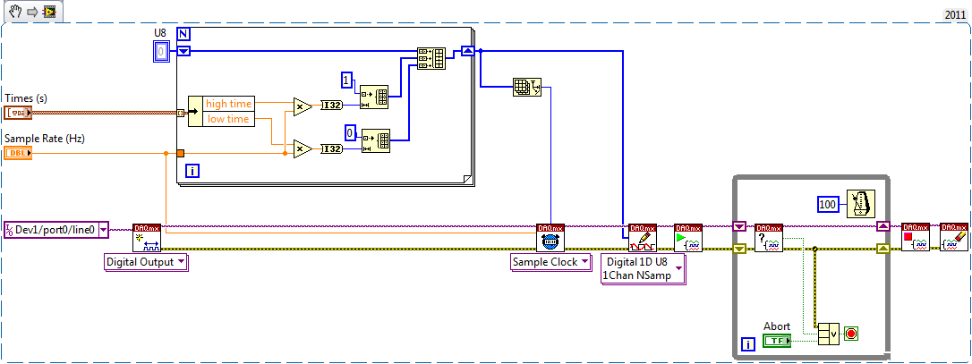
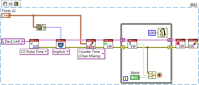
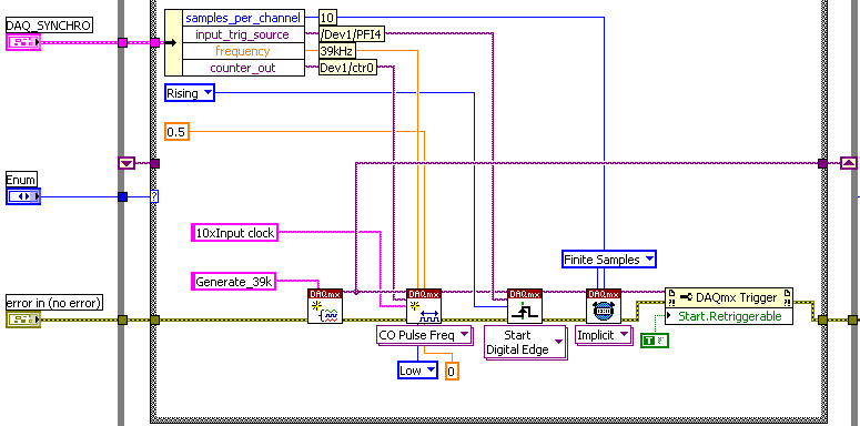
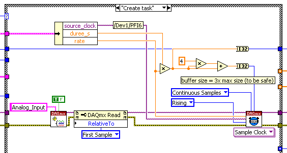
Need help with counters on PCI-6221 (37-pin)
Hi all
I have a system with a PCIe 1429 connected to a Basler A504 camera and one I use a clock generator (SRS CG635) of 3.9 kHz for trig the image acquisition.
On the same system that I need to add a PCI 6221 37
PIN to acquire:-2 HAVE 39 kHz, synchronized with the acquisition of the image. (Sample of the 10 for each image)
-1 meter to measure a frequency
The accuracy of my clock of 3.9 kHz being much higher than what I have on the DAQ card, I thought that an interesting option would be to have a redeclenchables DAQmx task that generates impulses from 10 to 39 kHz for each pulse received from the clock and then use it to trigger the DAQmx AI task.
Of course this can only work if the 'trigger' sources that I defined for these two tasks do not take both counters that I have on the card.
So, let's describe the DAQmx tasks:
-Here is the one who generates the 39 kHz on 0, the counter of the 3.9 kHz I entered as a source on PFI 4 trig
-This is the task of analog input for which I put the trigger on 6 PFI.
It is: I have "softwarely" know the jury to deliver output (Ctr0) 6 FBP counter? And if so, how?
Thanks in advance for any help!
Maybe you missed something that I didn't really point out in my post. The method I described would use the external clock of 3.9 kHz precise as a sample clock, so you would * not * be in danger of loss of synchronization in 1 s per day. You need to only son of this clock signal in a stem of PFI available and configure the task to HAVE it as a result. The 80 + kHz clock that controls conversions within each sample cycle * would * be generated by the jury of 6221, but he don't would not accumulate any out-of-sync error because he gets "retriggered" on each edge of the 3.9 kHz precise clock.
-Kevin P
Maybe you are looking for
-
A week ago my twitter has been hacked and I use the same email to my ID Apple and twitter. I changed my password on the Apple ID, just in case but you think it would be smart to just a new Apple ID?
-
Satellite x 205-overheating problems
Hello, I have recently had problems with my Satellite X 205 get well over 80 C 74 C while playing games and Idle. I solved the problem for several days of cleaning of dust on the computer with compressed air can. Unfortunately, the problem has increa
-
Impossible to install other systems on HP desktop PC operation p2-1334-screen white/blocking
Hello I have a desktop HP new-1334 - AMD E1 - p2 1200 Vision. Packed with Windows 8 x 64. I want to install Linux distribution: Ubuntu 13.04 on it. Problem: [I get a menu of text mode Linux distro who ask me if I want to install, after you have selec
-
Reinstalled Microsoft Xp professional and have now no network card
I reinstalled Microsoft Xp professional due to problems with the computer. Now, I don't have access to the internet and the network card drivers are not displayed
-
There is something that is eating up to 1 GB at a time, about a day, on my hard drive space
need help, there is something that is eating up to 1 GB at a time, about a day on my hard disk space (drive c: to be precise). I don't know what is the cause, but its just embarrassing for me to see my memory space has fallen by nearly 10 GB per week