prob in the acquired signal frequency
Hi frnz,
I have a prob in the acquisition of a signal. Using hardware DAQ iam generating a signal acquring and iam the same sine. During execution
I need to change the frequency. The problem here is the delay by changing the frequency. If the sampling rate of output is 1000 then
is a delay by varying the frequency. If the o/p is 20 k then an immediate change of frequency occurs, but the frequency
granted here is a multiple of 20 based on the rate of O/P.
For example: generated frequency = 10 Hz
O/P RATE: 1000 ==> acquired frequency = 10 Hz
O/P RATE: 10000 ==> acquired frequency = 100 Hz
O/P RATE: 20000 ==> acquired frequency = 200 Hz
Please help me with this prob...
Hello. Here I attatched my VI. Go through tat...
Tags: NI Software
Similar Questions
-
I want to maintain the "frequency of sampling to report signal frequency" a constant.
I want to generate sine waves of varying frequencies, say, from 1 Hz to 1 kHz. Sometimes, a swept frequency sine wave. The problem is that I want to maintain the "frequency of sampling to report signal frequency" a constant. That means, the sampling frequency must be 20 or 30 times the frequency of the signal. This should be done automatically. For example, a sweep of 1-10 Hz, if the sampling frequency is 30 Hz at the beginning, it should be automatically updated at 300 Hz as the frequency of the signal reaches 100 Hz. Someone you will suggest a possible solution?
The basic generating function function has an entry titled "sampling info". It is a cluster and one of the elements is the number of samples. You just need to set this based on your frequency.

I suggest strongly that follow you the course 101 of LabVIEW.
-
frequency of the digital signal 6009
Hello, how to generate the digital signal with frequency 50 Hz using NI USB-6009?
You can take a look at this:
Can I use a generation of impulses with the counters on the USB-6008/6009 case?
-
Acquisition with USRP 2953R of the GPS signal
Hi all
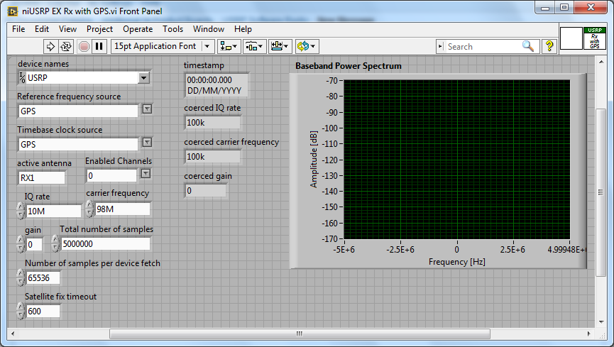
How can I configure a 2953R USRP receive GPS signals? I have an antenna VERT900 connected to the GPS ANT of the USRP port, but in the example VI 'niUSRP EX Rx with GPS', I can't reference this port in the field 'Active antenna'. I put only things like TX/RX or RX1 etc. Should what values I put in other areas as well? I know that the L1 band is 1575,42 MHz.
Hello
The example you posted shows you how to acquire an RF signal on the ports of the USRP with internal clock RF and sources of reference defined in the GPS.
To make it work properly, you must have a GPS antenna connected to the Terminal on the GPS device and installed in a place that receives a good level of GPS signal.
The other control of antenna on the schema defines the port on which to receive the RF signal.
If you want to capture and analyze the signal GPS (RF) itself, you can tune into the front-end RF (carrier frequency) at the right frequency of GPS band and connect your GPS antenna to the RF port.
You can use the simple niUSRP EX Rx continuous Async.vi in this case (but may not work due to the very low consumption of GPS RF signal)
-
Time scale does not properly after separation of the two signals of virtual channel
Hi all
I have a problem when I use a virtual channel with two analog inputs. I'm cutting the two signals into two separate tables of waveform, as shown in the attachment. The two signals seem to be reading very well, the problem is that the time scale (x-axis) begins to act on the strange. Seconds displayed time seems to keep jumping up and down at a high frequency, resulting in the two signals of displayed does not correctly in the table of waveform. Could someone please try to help me? Any help would be greatly appreciated!

Thanks in advance.
Try to acquire a signal with first time information. You can replace the DBL 2D with a data type of 1 d wave. You don't need this code extra silly - just a function of Board Index to get the separate channels.
-
Problem when the PWM signal combinning and analog signal TOGETHER!
Hello everyone,
first I DAQmx 6212, and I need to run the water pump small (9V - 16V) that should be driven by a PWM signal; I also have a motor (5V - 13V) for a water supply which must be controlled by an analog signal and it has built in a force feedback potentiometer, I logged onto this potentiometer correction + 5V the DAQmx and used the output voltage of the third extremety as a value to diagnose to know the position of the engine.
My VI shows:
1 is a normal meter production to create my PWMout signal.
2 is an analog input, I use it as a PWMin to the LabVIEW to diagnose what is happenning in my pump water through the cycle and frequency.
3 is an entry of the third extremety of the analog potentiometer.
4 is an analog output that I used as power supply of the motor valve and I used an AC/DC amplifier for aplify signal the DAQmx and the motor road, between the two (3. 4.) I made a comeback with a few calculations, I had a P-controller to know the real position of the engine valve.
My problem:
When setting to 1. and 2. in the same VI only, I get an own PWM output with no problem.
also with 3. and 4. in the same VI only i can control the motor valve without any problem.
but when I put all these 4 set found in the attached VI, I have a problem as the engine valve turn continuously without stopping even if I change the position of the valve between 0 and 100%, I should mention that I see a PWM normal outside a signal on my oscilloscope, another thing to delete one of (1 or 2) and run the engine valve VI works fine without any problems.
so this my problem, if you can think of any solution please let me know.
Thanks in advance for your help.
Kind regards
Caliente
Here's your VI, slightly modified so the two analog inputs belong to the same task. This if only for purposes of illustration, I him have not tested. You will still need to do some debugging.
While changing your VI, I noticed another potential problem with your original configuration. You have configured the two tasks of AI for the same frequency, but read you 10000 samples of one of them and only 100 samples from the other (and throw it most of it). Data acquisition data are buffered, and if you read as fast as you acquire, the buffer fills eventually. If you read 10,000 samples of a channel, and the other channel acquires at the same rate, then when you read from the second channel you will get old stale data or an error full buffer.
-
Hello
Before all sorry for my English, I'll try to do my best.
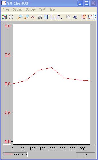
I'm analyzing a data acquired with a FFT, but I want to refine or reduce the frequency of each 'window' (I only want to analyze the 0-350 Hz region)
in order to see better where my maximum in the frequency domain is.
If you have an idea where I can edit this wide frequency in order to refine the plot, please tell me!
Thank you very much!
The sample rate determines the scope of the FFT calculation.
Using the Nyquist theorem, if you sample a 1000 samples per second, the FFT will calculate the range 1000/2 = 500 samples per second.
You NEED to taste at least twice the highest expected frequency in order to use the FFT module to find this frequency.
The resolution of the FFT module is determined by the size of the block. For the spectrum of amplitude by default, TFF will display a block which is also 1/2 on the incoming block. Size of block = 512, FFT block size is 256.
You can increase the resolution by increasing the size of the block and also by changing the size of the block to a number which can divide the sampling frequency. For example, if the
sampling frequency is 1000 and the block size is 500, the FFT output will have a resolution of 250 on a beach of 500.
You can use the data window module to change the block size - increase it to use more data and to increase the resolution of the calculation of TFF. Decrease that it resembles an interval of time smaller and lower resolution of FFT.
I hope this helps.
-
NEITHER USB 4432 readable voltage i.e. the ASPM signal conditioning
Hello
For what I understood that the USB-4432 entries must read IEPE accelerometers report. Read a voltage signal conditioner of my sensor ASPM IE using the option 'IEPE-off with AC coupling.
Thank you
1. What if I use the 5th cahannel of
4432 read the square wave pulse width, i.e. the digital signal
tachometer using any function of sounds or labview software and
Vibration Measurement Suite. If so, how precis specific will be read
frequency (speed) compared to meter modules.Channel 5 is the same as the other channels of the 4432 except it lacks excitement IEPE and TEDS. I can't really say how "accurate", it will be at a faster rate because of the delta-sigma ADC. Someone else wants to chime in on this one?
2.
Is available to trigger analog acquisition of digital triggering. If so, is
It possibel to read all 5 channels togather in a single task.You're talking about!
3.
If there is only one PFI then is possible to trigger two
different tasks, i.e. a task of 02 strings with front amount and
a further task of 02 channels with the falling edge of the PFI even.There are 8 PFI lines, but can only be used on the device at the same time (it might as well be one PFI). You must have all the channels you want to raise in a task and use one as the trigger for starting digital PFI lines. (i.e. 'no'
... have a stain on the front and the other on the falling edge won't work, a task only by digital triggering)Germano-
-
[FPGA] Problem with the sinusoidal signal generator
Hello!
At first I want to apologize for my English is not my mother tongue.
Hardware and software I use is:
LabVIEW 8.5
NEITHER RIO 2.4.1
NEITHER cRIO-9014 (controller in time real CompactRIO)
NEITHER cRIO-9104 (chassis and FPGA)
NEITHER 9264 (16 channels, +-10V, 16-bit voltage analogue output Module)
I made a very simple FPGA VI: a while loop, generator of sinusoidal signal and a FPGA of e/s node in the loop. I've specified the Gnerator settings by following the path:
Frequency = 50 Hz
Amplitude = 1
Phase shift = 0.00
Size of the table look-up = 1024
= 16-bit amplitude resolutionFPGA clock frequency (40 MHz)
But the wave of "sine" I got is not what I wanted to get. First of all, its amplitude is 1 V. shouldn't it be coded on 16 bits? If I wanted to get 1V I should have specified Amplitude as a 3277. In addition, 'sine' is not very detailed, it's look like "steps", as many samples vere missing. What I did wrong? I checked the samples and tutorials, I did everything the same way. A I forgot something or not has not specify other parameters?
Thanks a lot for your help!
OK, I solved a problem. It's embarrassing to admit, but maybe this will help someone else
 I blame my inexperience
The main solution to the problem was changing calibration of calibrated RAW Mode. After that, everythoing works as expected. I had a problem with a sample because I was using a multiplier to control the generated sine wave amplitude. But... She was set to 1 in the sinusoidal signal generator. That was the reason for waveform Gradin. Please, don't laugh too much

In any case, thank you for an answer! It is now resolved
-
Align the two signals and measure the Phase Shift
Hello
I do an experiment in which I use the NI USB-6221 DAQ card. The jury is able to make 250 k samples/second. I want to measure two voltages in a circuit and find the phase shift between them at frequencies between 1 and 10000. First I ouputted a wave sinusoidal frequency variable through the Commission and applied to a test circuit. Then I used the Board to measure the two tensions consecutively (thus reducing the maximum sampling frequency at 125 k). I used the signals align VI and measured the two phases and then calculates the phase shift (VI attached in Phase 1). It worked well for the test circuit I built in which the phase shift went way logarithmique.20 degrees ~84.5 degrees and then stabilized. At frequencies above 5 000 Hz phase shift must have remained constant, but it varies more or less 1 degree. When the phase shift is 84.5 degrees, present a degree of variability is not particularly explicit. When I asked my program on the circuit that I really wanted to measure, the phase shift went from-. 5 degrees up to about 1.2 degrees. The change in the values of phase shift at high frequencies (> 3000) was environ.2 degrees. Given the small phase shift, this variation is unacceptable. Now I tried to use a sequence to each blood individually (increase the maximum sampling frequency to 250 k) and then align the two signals and measure the phase of each shift. When I use align it and re - sample Express VI to realign the two signals, I get the message "error 20333 analysis: cannot align two waveforms with dt even if their samples are not clocked in phase." Is it possible to align two signals I describe here? I enclose the new VI as Phase 2
Matthew,
I think I have an idea for at least part of the problem.
I took your program data and deleted stuff DAQ. I have converted the Signal on the chart control and looked then what was going on with the signal analysis.
The output of the Waveforms.vi line has two waveforms, like the entry. However, arrays of Y in the two waveforms are empty! It does not generate an error. After some head scratching, reading the help files and try things out, that's what I think is happening: the time t0 two input signals are 1,031 seconds apart. Since the wavefoms contains 1,000 seconds of data, there is no overlap and may not align them.
I changed the t0 on two waveforms are the same, and it lines up. The number of items in the tables is reduced by one. Then I increased the t0 of 0.1 seconds on the first element. The output had both greater than the entry by dt t0 t0 and the size of the arrays was 224998. Reversing the t0 two elements shifts the phase in the opposite direction.
What that tells me, is that you can not reliably align two waveforms which do not overlap.
I suggest that you go to 2-channel data acquisition and that it accept the reduced sample rate. You won't get the resolution you want, but you should be able to tell if something important happens.
You may be able to improve the equivalent resolution by taking multiple steps with a slight phase shift. This is similar to the way that old oscilloscopes of sampling (analog) worked. Take a series of measures with the signal you are currently using. The make enough average to minimize changes due to noise. Then pass the phase of the signal of excitement to an amount that is smaller than the resolution of phase of sampling rate and repeat the measurements. Recall that I calculated that for a 5 kHz signal sampled at 125kHz, you get a sample every 14.4 degrees. If shift you the phase of 1 degree (to the point/mathematical simulation), you get a different set of samples for excitement. They are always separated by 14.4 degrees. Take another series of measures. Transfer phase another degree and repeat. As long as your sampling clocks are stable enough so that frequency does not drift significantly (and it shouldn't with your equipment), you should be able to get near resolution of what you need. The trade-off is that you need to perform more measurements and may need to keep track of the phase shifts between the various measures.
Lynn
-
Hello:
I am on the show dealing with the identification of the system. The process is as below:
First of all, I use a sine sweep signal (bandwidth is 0 to 50 Hz) to stimulate the actuator;
Second, I use a low-pass filter (the cutoff frequency is 45 Hz) to filter the response signal, like the image below.
-
4 counter of entry & 6 the input signal HELP
Hello friends,
I have a small problem, would be great if someone can help me.
I use the counter inputs on my CQI data. Harware to measure the pulse of my sigal entry width.
Since the material has only 4 entries of meter I can connect 4 channels, but I want to measure the pulse for 6-channel width.
Is it possible to use the 4 available counters and measure 6-channel?
Thank you
Kind regards
REDA
In my example (very basic), you can just increase the timeout for ~ 10 + seconds to ensure you acquire the pulse. It is possible that the pulse is not present in the ~ 10 + second timeout, you must also handle the timeout error, so it is not wrap around back through the shift register and prevent future readings to run.
Of course, the downside of this is that it could take up to ~ 60 seconds in order to gain all 6 channels in the worst cases. The example was really just intended to show how we can use a single meter to acquire multiple channels in the estate.
The best way to do it with meters would be to run tasks in parallel (up to) 4 meter. The first 2 tasks to finish with their initial acquisition should then measure a second channel. This could still take about 20 seconds if no signals are connected however.
If you want to trade a lower resolution of measurement (and memory use more) for a lower upper limit on the time of measurement you can acquire a second time 10 window using the call digital inputs instead and use software to determine the duration of the pulse by analyzing the acquired table.
Best regards
-
order a fan with USB6251 and the Daq signal accessory
Hello
I have a school using Labview project and the USB6251 connected to the Daq signal accessory card.
The Labview program must read continuous temperature (Ia 4 channel, internally) temperature probe connected to the accessory of Daq Board signals. When the temperature reaches an established value, then a led on the front panel should be lit and a singal output data acquisition should start a fan connected to the acquisition of data which cools down the sensor, then stops.
Would it not be possible to do something like that? Even if I generate a square signal and the fan only works on the State of the signal. The fan requires at least 120 mV DC current. I'm afraid that if I take these courses for the acquisition of data, I could damage the unit.
Thank you.
I guess you mean 120 current my DC
. If you look at your spec of daq card, you will find that the current max are far below 120 my. This applies to the two analog out and digital out. Take a look at this site, it may be useful to some. site nice http://www.me.umn.edu/courses/me2011/robot/TechNotes/motorcontrol/motorcontrol.html . If you want the speed controller, you have two options PWM or voltage of the motor regulation.Good luck
-
Multiplexing of signals microvolt and conditioning of the right signals
Hello
We have 22 signals in our system. We must be able to measure any subset of these 22 signals. Usually, we carry out a number of measures IV 4points of separate devices on a SUT (sample to be analyzed). Two of the 22 signals may represent the pair of voltage measure 4-point IV, depending on how it was KNOWN is bonded. The level of the signal of tensions is in the 100s in the uV range and I need a precision as much as possible, so the unit or same sup - uV numbers. So far, we had all the 22 signals connected to a box (selfmade) acting as a distribution point, where a connector (SMB) is available for each signal. We then manually choose which two of the 22 that signals will be connected to a differential amplifier silent instrumentation (also selfbuilt), according to it was KNOWN patterns of liaison. The amplifier with a gain of typically 1000, returns the signal to an acquisition card. The current (excitation) is read separately.
There is a problem with that. We need to manually switch the connectors in the distribution box to select a different device on it was KNOWN and flows to the amplifier. This is not good for a number of reasons that I can't go here.
Therefore, I would like to multiplex these 22 signals to several outputs (for future scalability) who will be wired for the conditioning of signals. There is no manual connection/disconnection of these signals in this way. The first question is: can a matrix switch or multiplexer be used to route signals reliable microvolt? If so, then what kind: electromechanical, Reed relay or a transistor? Is the thermal EMF in the specifications of multiplexer/matrix relay just a lag, or is - that noise?
The second question is: what card/signal acquisition solution (so no selfmade equipment and legacy) products OR only using the same line that the matrix/mux can reach 1uV accuracy of treatment? For us, offset offset is not a problem since we measure the device in 2 quadrants and later cancel it in the software but the noise (and get the accuracy) is important. Our amplifier has a background noise of 3nV/sqrtHz and a bandwidth of 15 kHz. The system to replace must be comparable. I have the choice between:
- the SCXI based ones, instrumentation isolation (4ch) 1121 or 1122 amplifier modules (16 channels), with a ground noise that I calculate 20 and 30nV/sqrtHz respectively. They already have some functions of multiplexing btw.
- the PXI 628 x with a background noise that I calculate through 10nV/sqrtHz
- the PXI 446 x with the noise floor low 8nV/sqrtHz as stated in the technical data sheet
Module 4-way universal 24-bit NI 9219, who works with 2 samples per second has a very low noise total, but at a very low sampling frequency and I can't consider comparable to what we have now. In addition, the system must be able to have a few kHz bandwidth for dynamic action in the future.
Y at - it any other ideas?
Greetings
Aleksandar Andreski
-
Problem with the biphasic signal generator
Hello!
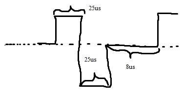
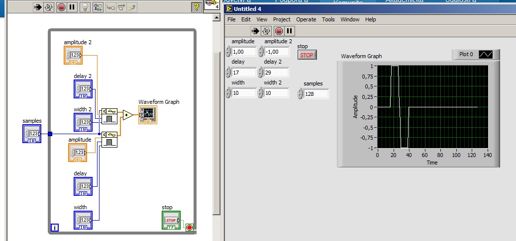
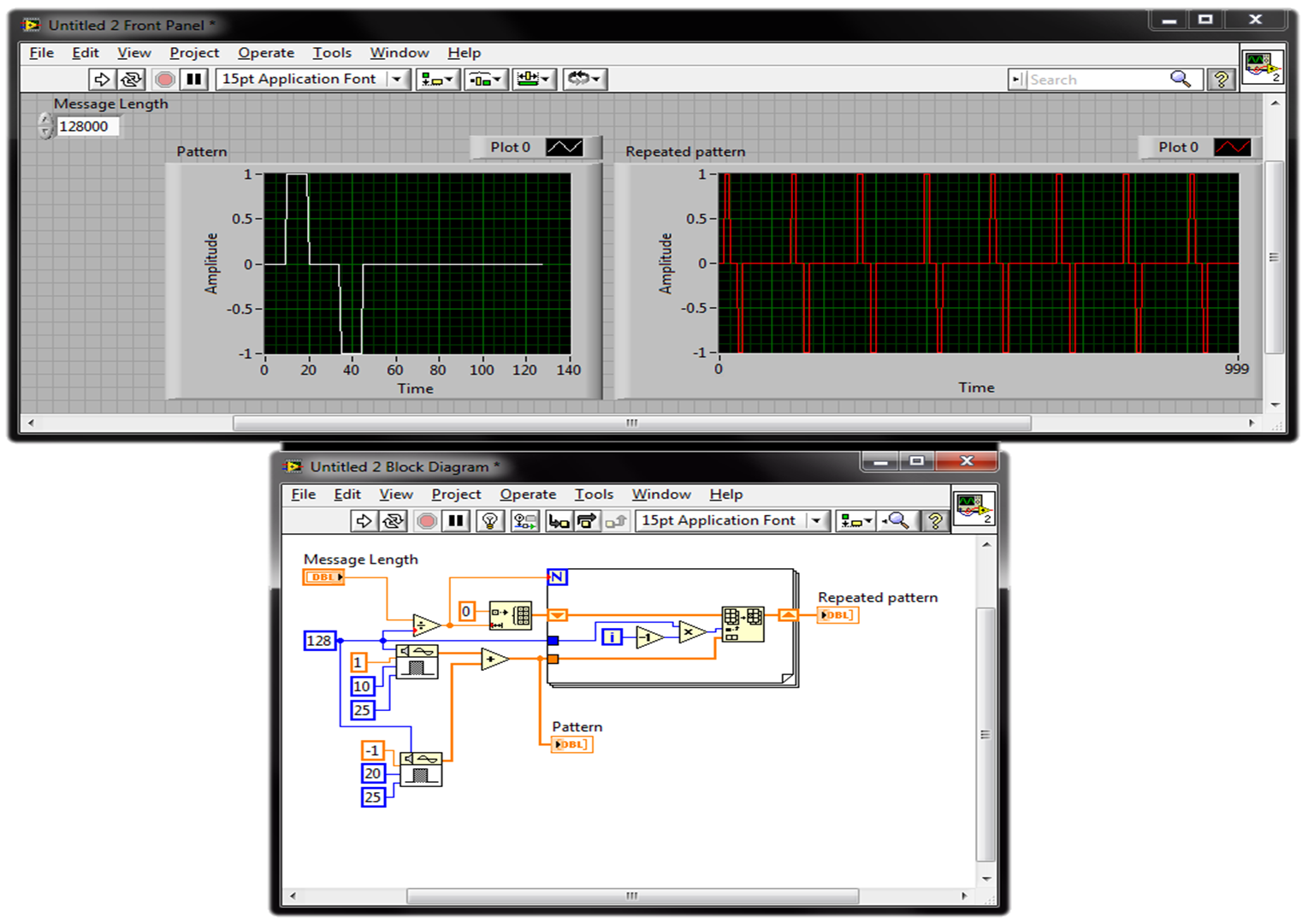
I filtered signal and detected envelope with OATS envelope detection.vi of given length. And now I need to modulate signal biphasic (photo). The biphasic signal should be the same length as my envelope signal. I want to be able to change the width of peak (25us) time and period, frequency (1 kHz), the biphasic signal amplitude (1). I know that I can start with pulse pattern.vi (check my diagram). But I don't know how to put together it me give only a single period. I have LabVIEW 2013.
You can repeat your profile of signals using a loop. Keep in the Middle the number of times where the model is repeted depends on the length of the theme of your message and the sampling frequency, you use the model and the message. Check this picture (just a quick suggestion):
best,
Maybe you are looking for
-
When closing Firefox version 3.6.10 with two or more tabs open asked me "Do you want Firefox to save your tabs for the next time it starts? I then the option "Save & Quit", "Quit" or "Cancel". This doesn't seem to be available in Firefox 4.0.1. Is th
-
very light gray printing black ink
I changed all my cartridges and black ink is printing very light - a light gray. I returned for a new cartridge, cleaned the heads and I always have the same question. All other colors seem to be good. A test page, colors only print so I can't tell i
-
Avoid the transfer of picture of peripheral iCloud
I have 2 iPhones connected to the same iCloud account. How can I avoid that the photos are synchronized between phones, but still allow backup on iCloud?
-
The build does not work the same as the vi in the project
I have problems with the exe file. I made a very simple example of what happens. To test JKI - Machine of State pending based on a string (Basic) v1.0 (openg) is necessary. I made a sample program with uses the JKI - State Machine on hold based on a
-
WRT54G2 show no light working, works of the AC adapter / CC
Hello I have just recived a new WRT54G2, I configured all security options and worked. My last step before production was to change the IP address of the local network, after I changed There was a screen saying 'OK', I turned off the WRT54G2 and plug