Probe questions
With appspeed, where are the sensors deployed on the ESX host? In COS?
Also, I read that AppSpeed probes cannot be migrated on guests that VMotion and DRS is automatically disabled for AppSpeed probes? This means that any virtual machine running on hosts with sensors are out of use about VMotion/DRS?
Hi cpad. The probes and the main server AppSpeed run as virtual appliances, i.e. as 'ordinary' virtual machines
The probes themselves cannot be VMotioned simply because they must cover their own affected ESX hosts. Other virtual machines in the cluster are not affected and can be VMotioned / DRS:ed as usual. In ESX maintenance windows probes may be closed as an ordinary virtual machine.
I hope that answered your questions.
Tags: VMware
Similar Questions
-
A few questions that probs make me look like an idiot!
Hello.
I used Photoshop for 13 years and has recently made the leap to Illustrator, and there were a few things bugging me. I use "my way" to solve them, but I'm sure that I'm doing it wrong, and it is much much too much time...
I'll have to use images to describe what I'm trying to say, so let's use my origami frog...

Right, here it is...
Now, I've read that all roads should be closed before sending to clients / impression etc... In my next photo, how you intended to close the path highlighted yellow? (And other similar used like retailer lines on the faces for example, because they are just a single line and cannot join their starting point)
Also, where I'm pointing red arrow... How can I do that triangular a different color of the article? Since the leg as a whole is the joined path, all these thinner strokes inside the leg are paths of the singular, open, as you can see by the yellow highlight... Am I supposed to 'outline' legs in the forms of small triangles? Because this seems very unprofessional, and I can't imagine it being boring and a lot of time with lines curves complex. So I must be missing something obvious.

^ Also, as you can see by the blue arrow, is not ending up with the angle of the leg. Is it impossible, because it is only based on the width of the line? Because close up you can see its not very tidy.
And finally... Can I use the plan less first Pathfinder tool on the coat of arms (yellow outline) the forest hidden rough edge behind the body layer, because once again, when you hover over the arm, it seems wrong again... But if I had less before bit hidden behind the layer of body to the line up carefully the outline of the body, once again, if the race of the body is thinner than the arms race, then the arms race would show beyond the edge of the line body giving the horrible yet?

This program can be very confusing. I hope someone can understand what I'm trying to say.
Thank you.
Shaun.
Cross validation, carano (a risk of leaving during the response).
Nice to see that it was settled.
Describing the stroke of the brain and less first plan will give you the ends that depend on the direction of the high path of the page by the cuts made (small fertilizer or curved segments that can be different angles), then the path opened as a result of a scissor cut will be just ends in accordance with your race > adjustment Cap.
-
Question Express airport w / AP Extreme problem
Summary... My extreme AP gen 5 died today. Loss of Internet connection and after vicissitudes of shooting during a certain time that is as it works but not of connectivity. Thought it might be my new provider, even if the performance has been very good for 2 weeks. Fixed prob was on my end after a call to customer service to see if he had reported outages and also wiring my modem to my iMac. I had the extreme as the main router wireless and wired AP expressly as an Extender. To get a temporality rear wifi, I use the Express instead of the extreme for the night.
Now my question, if I replace the extreme with another brand of router, can I get a hard wire to Express the other side of the House and use it as an Extender? I'm prob looking to get a new extreme, but I saw a few new routers about the same price with 8 Sockets Ethernet. I have most of my game and hard devices streaming already wired with a switch so I can get with the 4 Ethernet ports, just to think about the future because I'll eventually add a configuration of the camera and maybe another game console. Thank you
... can I get a hard wire to Express the other side of the House and use it as an Extender?
Yes. An Express configured to expand "using Ethernet" don't worry this device creates the network. A network "wireless" is a different matter.
I would not place too much importance on the number of Ethernet ports any particular router offer. Eight ports Ethernet switches are inexpensive.
I guess you did a "hard reset" of your extreme before giving up on this subject, and you also to reset the cable or DSL modem? They don't die that easily. The most common failure mode is the power supply, indicated by a dark light. The "hard reset" is the gold standard to resurrect the extreme apparently failed, so make sure that you have correctly completed:
On "hard reset" an AirPort Base Station: Make sure it is turned on, then press gently and his tiny reset button. Do no force more than necessary to feel a tactile click. Hold it down for five to ten seconds, enough until the LED flashes orange rapidly. Release the reset button. Then the led amber for about a minute. Then it will blink slowly, amber, once per second or two, you wait to set it up with AirPort Utility.
-
A few questions on Generate and measure PWM
I'm working on a project that requires both measures and generate PWM signals.
Currently, I have some problems with these two.
I use card PXI NI 6624.
1 issue with PWM measurement.
I connect the signal to the door + and GND for door. I hope that I can read that the width of the high pulse, casue the door will start the meter.
I use the code as in the example of a measure of the market (on the photo 1) factor. The problem I have is the values in the table also include low pulse, and these two values will be shifted in the table. So if I have the array index I can't get a stable number (in photo 2).
I want to know the reason and how to fix it.
2 problem with generating PWM.
I use another counter to generate the PWM.
I connect Vdd and Vss with a DC Power Supply 13.8V. I use a 10 KOhm resistance connect between Vss and output. I got a good signal with 13.8 V.
a > my first problem is the frequency is not stable. I put it at 122 Hz, and I saw him skip Hz 119 to 125 Hz.
b > my second problem is when I connect it to the PWM measurement, I did above the will of voltage up to 2.5 V. I tried with 1 KOhm resistance and it downs to 6V. When I connect a real controller with a 12V PWM, this signal is stable after I connect with channels PWM measurement above.
I would like to know if I did all this trouble. Cause be will use this PWM to simulate a value of the probe and it must be stable.
I enjoy reading and answering my questions.
Best regards
Thang Nguyen
Hey Thang.
Try temporal evolution and also remove the expectation of punishment in loop and add samples to read terminal. Attached, it's the comic book for this try this, it should help you.
Lab
-
USB-6210 voltage divider Calibration questions
I'm trying to calibrate 14 tensions that I read from a voltage divider in 14 channels of a device USB-6210. Attached is an Excel spreadsheet of data I'm trying to understand. On the bottom of the sheet, I applied the same voltage to all channels and draw the raw tension for all channels and the differences between the expected voltage and voltage of raw. I find that these differences are not constant but linear I do not understand. I then use the basic linear function to find the factors in the top of the worksheet. Therefore, in the upper part, I read the input voltage by using a probe high voltage and voltage of Labview which has been adapted by the linear function of base in the background. Most of the multiplying factors are ~ 1000 as expected, but the tensions for the last 4 channels are significantly different and are not linear for the last two channels. I mounted the two worst voltage channels with polynomial which is ok but not make any sense. Does make sense to anyone. I'm using Labview 9.0.1 and Windows 7. I ran Diagnostic Utility for the acquisition of data on the device and it passed all tests. I looked into the issue of ghosting, but the criteria seem not valid here because of tension in the neighbouring country of the channels is small. I also enclose the VI that supports voltages raw to show how these functions are used. According to me, the results are stable and precise, but I can't explain the above mentioned discrepancies.
The problem was solved by changing the sampling frequency in the DAQ assistant. I think the default frequency is 1 kHz and I had given up to 750 Hz. By lowering the frequency 150 Hz, the capacitor is allowed time to discharge so that no ghost image occurs. In summary, the question always was ghosting and solve the I: question
-Removed in the wizard DAQ, channels that have been disconnected and therefore not used.
-Change the wiring to the DAQ assistant by sending the low voltage in channel 1 and the second lowest voltage on channel 2, etc.
-Change the sampling frequency of 1 kHz to 150 Hz to let the capacitors discharge time.
-
Hi all
I have a question about debugging - specific probes. Is it possible to link and save the values on a wire (with a probe) which is a loop for the loop counter (or even a secondary value)?
When I'm debugging code to a state machine that I often more easy to wire to the top of the State and the value, I am interested in a cluster, and then use 'generation antenna' and a registry change to add this element to each loop. I could also do this by indexing just out of the loop too.
Once execution completes etc that I can look at the table (either using an indicator or a problem) to see what has happened to the value to each State/loop. And often, I know exactly where my code was wrong.
My question is: is there a way to do this using regular probes without having to build an array? So, for example, I probe a digital wire and get a table of responses rather than just the last value on the wire?
Thank you
Dave
I found this nugget that does exactly what I want - it's a custom probe developed by Darren.
This post on the Exchange of ideas gives to think it should be at least provided with the package LV either integrated in the dev environment. Well worth voting for!
-
Question of entry of NOR-PCI6221 AND anolog scB-68
Hi, two questions please.
(1) I use neither-pci-6221 DAQmx and scb - 68 to input voltage (0.001 ~ 0.00001v) and temperature (thermeocouple sensor), I use AI0 and AI8 as voltage channel and Al1 and Al9 as channel temperature senser, I adjust the swiths in scb - 68 box in "Default Fcatory", I can get the voltage signal good and then I swith to mode "activate (differential) temperature sensor. I just get only the temperature signal, the teminal tension do not work, Yes, I put my chain tension differantial mode, still do not work, why?(2) can I leave the channel two work together? I want to the change in temperature of the probe when I measure the voltage.
Thank you
-
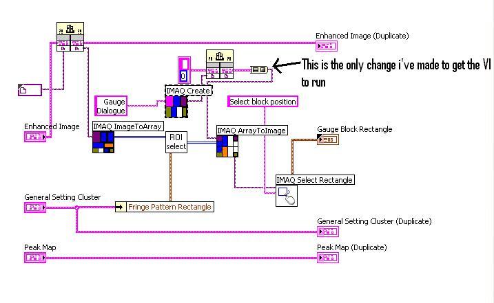
Going from 8.2 Vision Vision 2011 questions
Hello
I was update a VI wrote with Vision8.2 for the 2011 version. My main questions were so far a number of broken VI due to different types of connected data set-use the 'cluster from IMAQ image to the image data type' & under 'IMAQ image to the cluster of the image Data Type' VI appeared to solve this problem and the main program was able to run without error.
However, when you use this "Marquee IMAQ" part VI, no image doesn't appear on the screen, so there's no rectangle to select... This vi is part of a larger main VI with other "Marquee IMAQ" functions in this document, which seems to work ok (picture)
I have never used NI Vision before and have debug this fairly complex VI without really knowing something (just got the main training program in LabVIEW) so if anyone has any ideas, why does not appear a picture that would be great.
Joined the VI and a picture of him
There is also a sub VI called 'Select KING' appearing with him so I would add that both
Kind regards
Dave
Hello
Please submit this information, my name is David and I am an engineer of Applications at National Instruments.
It seems a bit strange that you use other instances of this VI and they work, it would tell me that the reference that receives the image is not valid. I tried to run the VI and created a probe on the entrance of the IMAQ select Rectangle VI and noticed that there is no image entered. Now, this means that the issue is not with the VI itself, but the way in which you create the IMAQ image. Currently, it is difficult for me to say why that might be the case because I don't know what is happening in your dll, but if I were you I way back a little and just make sure that the image is correctly entered at each point and you are able to see the image of the other side.
I hope this will be useful.
Kind regards
-
do not show an image of the probe
Hi all
I'm binarizing then clean an image with two particles in the filter of vi. I use vi "Copy picture" before each operation and then display the image. When I put the tool probe on each wire image it shows something different from what is shown in the pictures. Specifically, images of the probe show all the removed particles while displayed images show the results that I expected after each stage of the treatment.
So here's my question: why are the images of the different probe what evidence the individual VI?
Hello
your image binary seuillee only has two values - 0 and 1. There is virtually no contrast between the pixel values. Your display on the front panel has probably enabled binary pallete. Then, right-click on the image of the probe and select the binary palette. Or try to multiply the image by a constant value (255 for image u8).
Best regards
K
-
question about cleaning the sensor of the A57
Dear community of Sony,
I have several questions about the cleaning of the sensor of the A57.
Recently, I noticed several dark specs appearing on images when shooting at low opening (F20, F22), especially when there are high for them (like the sky in a landscape photo) contrast. To my knowledge, I've categorized as possible of dust on the sensor. I have read the section of the manual about cleaning the sensor and followed the procedure. However, the problem remained. I have previous experience with cleaning of the more resistant the probe of a Sony NEX dust particles, so I applied it to the A57. I used the specialized sensor cleaning tools combining two parts kit - wet and dry. Noted little dust on translucent mirror as well, so I cleaned up afterwards. Later, I considered this mirror could have some specialized coatings.
So my first question is: should I have done some permanent damage the mirror or the sensors? Currently, the camera works OK, although some features of dust still remain. It seems that I had pushed some of them to the edges of the sensor.
I'm not so happy with the tool that I used. I'm thinking about this one for a more thorough cleaning:
http://www.digitaltoyshop.co.UK/Eyelead_sensor_cleaning_kit_SCK-1_Sony_Alpha_A57_t2836_6789
It is marketed as a tool for A57. Should I use it?
Thank you in advance?
Best regards Angel Marinov
PS: I'm really happy with my Sony A57 and the NEX. They made me a fan of Sony. So, I want to use this topic to also say thank you to the developers of Sony.
Hello Angel!
Read the following steps carefully and let us know if you have any other questions.
-
Hello
I would like to know a reproducible method to check the key of a sensor SSH server from a windows client. I usually use my ssh client like putty, but tried 2 others in this pursuit.
On the sensor, you can use the command 'show ssh server-key' to display the key in its raw format (decimal), but also a MD5 and Bubble Babble fingerprints.
When you connect with PuTTY for the first time, PuTTY shows you a fingerprint, which I suppose is MD5 because it is 128 bits in hexadecimal. But which does not match the footprint of 128 bit hex MD5 shown via command line of the probe.
I tried a 2nd client who gave an imprint babble, but even once, does not match the footprint of chatter that makes the line of command of the probe.
I tried a 3rd customer who shows the MD5 and chatter of fingerprints. These fingerprints match those displayed by the other SSH clients and of course, then no not match what the sensor showed.
Finally, I tried to watch the complete key stored by these clients to host files or the windows registry, to compare with the full key indicated by the line of command IDS. All 3 clients display the key in hexadecimal format, while the sensor displays in decimal format. I can't find a hex to decimal calculator that can handle 1024 bits of an input value!
So if I have to accept blindly to the key the first time my SSH client connects to a Cisco IPS sensor, I am of course open to a man in the middle attack initially connect. I can do some checks warm & fuzzy (connect from the subnet of the probe & check my ARP cache entry MAC address is correct, etc.), but it seems that these fingerprints must be verifiable directly.
Thank you
KEP
This is the kind of a hack which may help.
Once you connect as a service account that you can SSH to the ip address of loopback of the probe.
"ssh-2 127.0.0.1."
-bash - 2.05 b$ ssh-2 127.0.0.1
Could not establish the authenticity of host ' 127.0.0.1 (127.0.0.1).
Of the key DSA is 2 c: 76:a2:b3:67:e2:cb:46:8 d: ee: 3B: 41:92:ac:61:19.
Are you sure you want to continue connecting (yes/no)?
The service account to connect through the ip address of loopback of the probe, so there almost know possibility of a man in the middle attack.
(The only way to spoil it would be for the attacker to have a complete control sensor and charge its own program of SSH server on the sensor)
The "-2" specifies to use a LDAP version 2 client.
Now the big question will be the hexagonal footprint seen in the above question can be used to compare the information provided by your SSH client?
Let me know if this weird method still does not work for you.
I sent an email to our main engineer of SSH to see if there is a better method.
-
BlackBerry Z10 stupid but very interesting question on your blackberry microphone remote
Hello
I have a question that I now have a fight with 10 friends around a table.
There is a rumor in my country that your cell phone can be heard even when you talk, when he's just sitting idle in stand-by but turned on. As a person can open your microphone from far away and listen to whatever it is you're talking to the table.
My question is, is it possible? How is it possible?
Having been to many of the foundries around the world, I can say that it is feasible as possible but almost certainly not practical. He needs collusion on a scale from Golden to be implemented.
Any suspicion of a phone, this would result in it being gutted, the tops taken out of the chips, and probes introduced by expert monitoring and chip design.
What is possible, it is for your position to be checked by means of a phone and a phone to be cloned and calls intercepted. If you talk on the phone, the call can also be intercepted at the end of service provider and to recent leaks, it is a certainty that the Governments that, with the United States it seems to be one of the worst (or best) with a massive mainframes, passing to sift through all the calls of keywords to trigger.
Unfortunately, it's the world we live in now.
Hope, your dinner party went well and that you kept your dinner talk about hazardous materials.

-
BB Facebook SDK question integration.
Hi all
I joined BB FB SDK in my application. I had previously also included FB SDK in other applications and it worked fine. Once he took back me to my application, in previous applications. But in my current application, the behavior is not even. I met 2 different scenarios:
1. After you have entered the user name and password, rather than return to the application on a successful connection, it displays a page containing "Facebook" as a header and request to the user permissions for the application, and when you click "OK" displays a page containing the profile picture and button of type parameters and the content of the page is not clear.
2 another scenario is that I get a server 500 error, which is the same question as in the following link:
http://StackOverflow.com/questions/16181928/Facebook-BlackBerry-SDK-error-500
Kindly let me know what could be the cause of the issue. That's the problem with the settings of the application created in Facebook. Please provide a solution. Thanks in advance.
I was able to reesolve the issue by following the steps in the answer in the following link

http://StackOverflow.com/questions/9663228/BlackBerry-Facebook-SDK-prob-for-OS-7-0
-
Port Probe of unexpected reactions (repost)
I have a D - Link DIR-655 router. I regularly use use Shields Up! at Gibson Research (www.grc.com) to probe my systems to determine the secure port status (stealth, either open or closed) to help keep my systems.
Something has happened recently that I am at a loss to explain. I've added a rule for the router port forwarding to forward port 6789 (not the real port number - this is just an example) port 6789 on some computer on the network. After adding the rule, I surveyed a sample of ports (no-6789) and they have all reported as stealth (which is correct). I then probed port 6789. OK, he came back open, which was expected. Then I probed several other random ports, and they are now open, which was not intended. I then probed all the ports (below 1025) and lower surrounding 6789 and almost all were Open! Something is very wrong.
I turned on the port forwarding rule and ports reported stealth, feel everything was normal again.
I tried other ports and other machines and even the scans of ports and other machines connected, and the result was the same - open ports!
What in the world would cause something like that? It's like a probe to a forwarded port broke the router firewall, and all traffic was spent.
Do you think the router firmware is corrupted, or have I made some sort of mistake?
I haven't changed any other settings on the router I think would result in this behavior. I am experienced with routers and port forwarding and have never experienced anything like this.
Any thoughts would be appreciated.
Thank you.
Hello
Your question of Windows 7 is more complex than what is generally answered in the Microsoft Community forums. It is better suited for Windows IT Pro Forums. Please post your question in the Technet Windows Forum.
http://social.technet.Microsoft.com/forums/en/category/w7itpro
If you have other issues with Windows, we will be happy to help you.
-
Hi all
I saw zero Windows Probe events and its default action says 'change the package '. Please let me know what will be the exact action taken by IPS that I need to understand it perfectly. Please guide me.
Concerning
Kiran
Hello Kiran,
The action to modify the package signature line 1317.0 removes the package data probe Zero Window.
RFC 793/1122 allow no data 1 byte of data or even a package of comprehensive data in Zero-Window probe. If the window opens while the package is in transit, the receiving end can accept data. As the IPS has no way of knowing if the data will be accepted on the receiving end or not, it deletes the data. The IPS force package as a legitimate zero window probe and remove possible ambiguity on what data have been processed. Zero window probes are not malicious. The signature exists as a way to control the behavior of the normalizer. The behavior is necessary for the normalizer can maintain the proper workflow status.
Disabling this signature can cause the normalizer of a false positive in the following scenario:
Client server
------------------Syn>
-------------------ACK>
-ZeroWindow >
-ZeroWindow >
If the receive window opens while the ZWP package above is in flight, the customer accepts the packet normalizer will be ignored and the normalizer is out of sync with the data stream. The normalizer will begin to produce false alarms.
If the signature 1317.0 is selected, all data will be removed from the ZeroWindowProbe and there is no potential ambiguity.
Please let me know if I can help with anything whatsoever in addition under this thread. If your question has been answered, please mark the thread as such so that it is useful to other users. Also, feel free to note this thread to take account of your experience.
Thank you
Blayne Dreier
Cisco TAC team climbing
* Please see our Podcasts *.
TAC security show: http://www.cisco.com/go/tacsecuritypodcast
TAC IPS Media Series: https://supportforums.cisco.com/community/netpro/security/intrusion-prevention?view=tags&tags=tac_ips_media_series
Maybe you are looking for
-
Y at - it an option for a screen shared 4 instead of 2?
I found an add-on for a split screen, but it divides the screen into 2 parts, so I was wondering if there is an option or an another add-on which allows you to do a split screen into 4 pieces like this browser... http://www.bigbrowser.org/medias/scre
-
What are the details? Update firefox message warned me, it would take an action, which could be relevant details to this threatened action? I use Norton 360, IE 10 on windows 7 64-bit. Will disabling feature of Norton in Firefox "specific browser" or
-
Could not open/create a new connection in BT manager on Satellite M40
Bluetooh Manager is opened and is in the system tray.However, it is never possible to open/create a new connection in the bluetooth Manager because it always say "bluetooh is not ready." Troubleshooting is required, but no clear indication is availab
-
Satellite M70 - la motherboard will support 800 RAM frequency?
OK, here's my problem. I want to upgrade my laptop computer, the memory of s. The stick of RAM available alone, s speed DDR2 800. Can it work with my motherboard. 533 or 667 is not available. It's Toshiba satellite M 70.I downloaded CPU, motherboard
-
Why they charge for beats when there are much better streaming services that provide high-quality services for free?