read the mV signal
Hey,.
Is it possible to read a signal HERE, with a range of 1 mV-150 mV, thanks to an acquisition of data USB-6210?
How do we?
Kind regards
Filip Van Boxstael
-200 mV to + 200mV is a range. The DAQ hardware will measure a voltage within this range. If you need to measure something outside this range, you must select the next higher range. Since you mention 150mV for you the maximum voltage, 200mV beach is perfect.
Tags: NI Hardware
Similar Questions
-
read the analog signal 0-10 volts of NI6123
I'm reading the analog signal of NI 6123. The range of the analog signal is 0 to 10 volts. This works well when the signal voltage is 0 to 5v (0 ~ 32767). But when the signal is 5 to 10 volts, the value read is always 32767. I also tried the different reading function: DAQmxReadBinaryI32, DAQmxReadBinaryU16, DAQmxReadBinaryU32. The value is identical to DAQmxReadBinaryI16. My OS is windows vista. Here's the part of my codes.
**************************************************************************************************************************************************************************
Create analog data tasks.
DAQmxErrChk (DAQmxCreateTask("",&datHandler));
DAQmxErrChk (DAQmxCreateAIVoltageChan(datHandler,"Dev1/ai0:7","",DAQmx_Val_Cfg_Default,-10,10,DAQmx_Val_Volts,NULL));)
DAQmxErrChk (DAQmxCfgSampClkTiming(datHandler,"",RATE,DAQmx_Val_Rising,DAQmx_Val_ContSamps,RATE*MAXLAS));
DAQmxErrChk (GetTerminalNameWithDevPrefix(datHandler,"ai/SampleClock",trigName));
Create counter tasks.
DAQmxErrChk (DAQmxCreateTask("",&ctrHandler));
DAQmxErrChk (DAQmxCreateCICountEdgesChan(ctrHandler,"Dev1/ctr1","",DAQmx_Val_Rising,0,DAQmx_Val_ExtControlled));
DAQmxErrChk (DAQmxCfgSampClkTiming(ctrHandler,trigName,RATE,DAQmx_Val_Rising,DAQmx_Val_ContSamps,RATE));
DAQmxErrChk (DAQmxRegisterEveryNSamplesEvent (datHandler, DAQmx_Val_Acquired_Into_Buffer, SPLEEN, 0, EveryNCallback, NULL));
DAQmxErrChk (DAQmxRegisterDoneEvent(datHandler,0,DoneCallback,));
Start the task.
DAQmxErrChk (DAQmxStartTask (ctrHandler));
DAQmxErrChk (DAQmxStartTask (datHandler));
In the call back function:
DAQmxErrChk (DAQmxReadBinaryI16 (datHandler, SPLEEN, 3.0, DAQmx_Val_GroupByChannel, data.laser, MISS * MAXLAS, & (data.dataRead), NULL));
DAQmxErrChk (DAQmxReadCounterU32 (ctrHandler, SPLEEN, 3.0, data.counter, SPLEEN, & (data.ctrRead), NULL));
write data to the file.
data.cfile.Write (data.counter, sizeof (int32) * RATE);
data.cfile.Write (data.laser, sizeof (int16) * RATE * MAXLAS);
**************************************************************************************************************************************************************************
Thanks in advance
To make sure that your device is working properly, I recommend first to test the entry in measurement and Automation Explorer (MAX) analog. You can test your device by right clicking on it in the configuration tree and selecting test panels. See if you acquired signal 0 - 10V as you expect. The next step would be to try one of the sample programs that perform a task of analog input. These examples can be found in the start menu > programs > National Instruments > NOR-DAQ > text based code supported. Try an example that does an analog input continues and double bed (instead of binary data not adjusted).
Your program looks good at first so I found nothing that stood out. However, one thing to check is if your function generator (or signal source) expects a 50 ohm or high impedance. This could cause reflections of the signal and cause the device to possibly read a voltage of half of the desired value.
-
Problem in reading the PWM signals in myRIO 1900
Hi guys,.
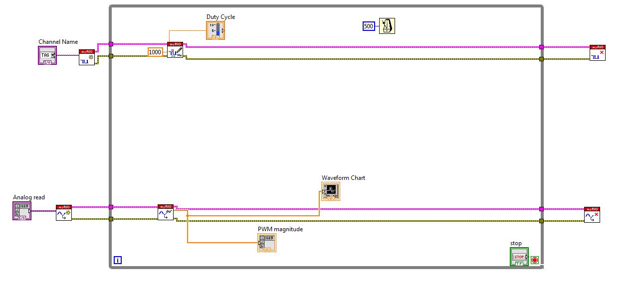
I work with myRIO to generate PWM pulses.
Here is the block diagram of my circuit.
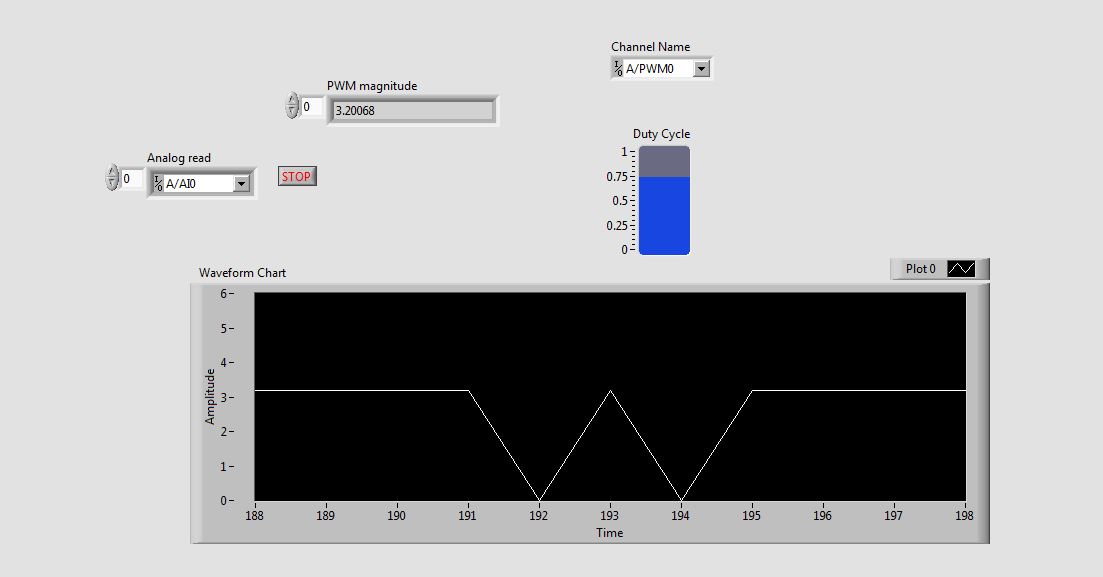
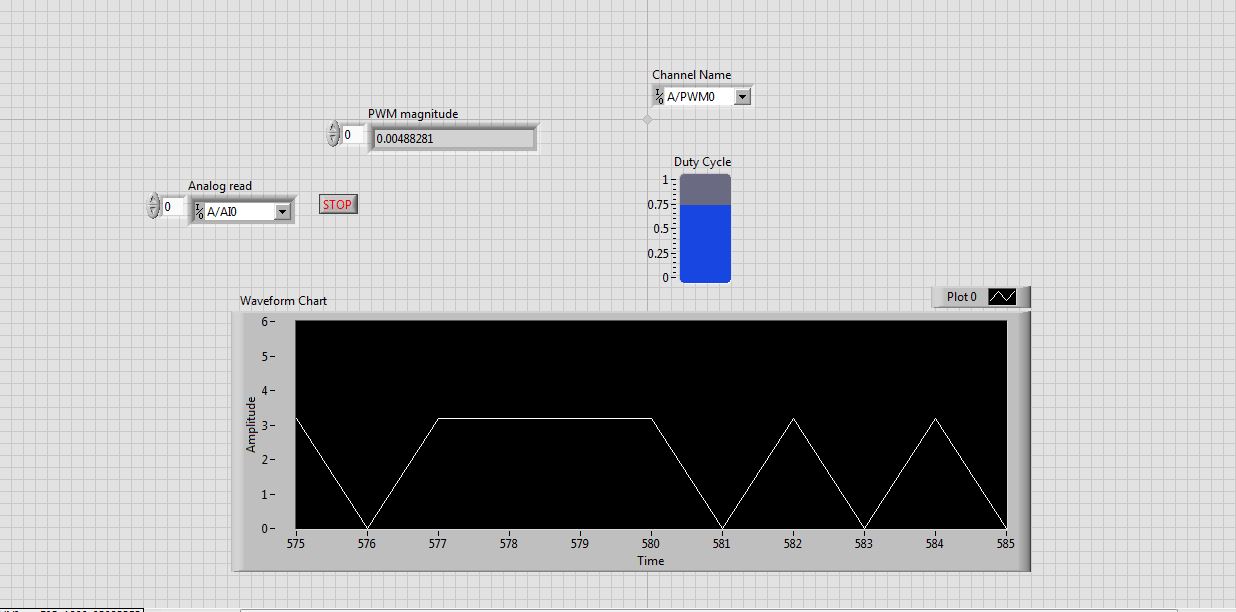
I connected external to the analog input pin PWM pin. So I can watch the PWM pulse in the waveform table.
But the waveform is not clear. This is as shown in the screenshot.
See that the waveform is not correct. When I'm watching the same PWM pulses in the CRO (cathode ray Oscilloscope, oscilloscope real in the real world), I get exactly the waveform. that is, the PWM pulses are generated correctly. But the analog read is unable to read the PWM pulses.
I faced the same problem with the pin of analog reading earlier when I read the input voltage. Is not give continuous reading of the voltage input.
Please guide me how to read these impulses via analog read.
Please tell me at what frequency range, I can use this myRIO to generate impulses?
I am able to use 40 kHz?
Hi rcs.
The desired pulse frequency is 10 KHz. My sampling rate must therefore 100 kHz, which is not possible in data acquisition mode. There is another problem with the myRIO. Only AI0, BI0 and CI0 has n-sample mode. The analog input pins is still have no n-sample mode. But in my project, I need 4 pins of I in n-sample mode, which is not possible. In addition, the sampling rate should also be favourable, which does not happen in my case. We can say that this is a disadvantage of myRIO with data acquisition mode.
The only alternative to solve this problem is to use FPGA in myRIO.
He can taste a 25nS rate.
But little complexity is there -
Here is my sensor
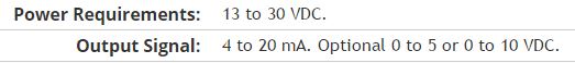
Pressure sensorHere's the DAQ data sheet:
Here are my issues:
First of all I don't know what is LO and HI exactly in the DAQ 9219 material.
Second, I don't know what pin code I should connect the DAQ sensor signal wire. PIN 4 or 5 pin? The sensor has three pins, and I guess I should connect the other two wires to the power supply.
Thirdly how to calibrate the sensor. In labview choose voltage in the wizard?I'm pretty new in this acquisition of data and I need your help.
Thank you
Hi SilasIII,
Hmm well 3 sons are probably on the ground, the power and the return signal. The datasheet for the sensor says:
First of all, you need to know which model you have (4-20mA, 0 - 5V or 0-10VDC). HI refers to the return signal, LO essentially means the land of the food that feeds the sensor. Then, you must get the 13-30 VDC supply. I don't think this should be too complicated and can be a simple wall DC power. You can learn how to create a custom in DAQmx scale. I hope that this is a starting point.
Kind regards
Eric
-
Hello
Installation program:
2 x PCI-6602
Configuration:
Sampling the five PWM signals of 50 kHz using five counters (2 on a map) and three on another for about 10-15 seconds by recording continuously.
All meter tasks are configured for DMA transfer.
Problem:
I get 200141 errors from time to time.
Question:
I tried to increase the size of buffer and all tasks of meter are set to DMA. In the error message the last suggestion is to "divide the input signal before taking the action. I don't understand this suggestion. What is meant by "split the signal before taking the action?
I am open to other solutions to the problem.
/Mola
Yes, I know that the 2 MB/s sound do not like much, but it's a way of high load very low tolerance to try to get 2 MB/s. You have 5 DMA controllers to negotiate access to the bus and each transmits only 1 or 2 samples of 32-bit whenever he gets access.
I've seen published baseline data where the maximum sustained rate was< 1="" million/sec="" (don't="" recall="" if="" it="" was="" mbytes="" or="" msamples). ="" as="" i="" recall,="" finite="" acquisition="" mode="" allowed="" higher="" rates="" for="" shorter="">
Ah yes, here is a link that leads to the other links. See the section on "The counter of the FIFO" in the first message. Do you see a * very * significant difference in the performance of the M series for the series X-series. Here are data for counters of the E series. (It is fair to note that the comparative analysis was conducted with a much older PC hardware). For the 6602 counter chip was designed between E- and M-series series, so you can probably expect performance in-between.
Also note that the benchmarks seem to have been done with a task of window unique tent of owning all the bandwidth PCI as possible. Since you would have 5 tasks they negotiate access, you lose definitely even more overhead. In addition, for fair comparisons, your 50 kHz PWM would act as a measure of 100 kHz since you have 2 semiperiods to DAB per cycle of 50 kHz.
Now that I've seen benchmarks once again, I am convinced that it is a no-go for you with just the 6602. The good news is that the series X-series seem able to yet more ridiculously than I remembered.
-Kevin P
-
I'm reading the entries of a parser to communicate with the computer via a USB port. I tried to use the RS232 DASYlab input module, but he always says he's waiting for a signal. I have attached the Protocol for the parser. Can what settings I change to display these values?
Basically, if your device is equipped with a USB adapter and the adapter is not simulating a RS-232 port, you have only two choices:
(1) the manufacturer will provide you with a driver DASYLab in the same way that it could provide one of a LabView
(2) the manufacturer as a programming library with, at least, a C or Python library. In this case, you can write your own driver in Python using the script module in 13 DASYLab
If the unit has a RS232 Simulator, then you need to look in your manual and use the correct symbol.
-
Desgning a VI that time / interrupts a film according to the input signal
Basically, what I'm trying to do is to design a VI who plays or pauses a movie according to the signal it receives. This VI will be used with an EEG device, and what I want to do is play the movie if the signal exceeds a certain threshold, and it stops if this isn't, in other words a VI that responds to neurofeedback.
As I don't have access to the equipment of the GET yet, I use a sine wave at the moment than the EEG signal in VI of the attachment in this post (which of course will be later replaced by waves of EEG recording), and what I want to do is to read the film if the signal is greater than 0 and put the film on hold if the signal is less than 0. Any help would be appreciated
Kind regards
varkong
I have included the code for the LV8.6 version.
Concerning
Prashant
-
NEITHER USB 4432 readable voltage i.e. the ASPM signal conditioning
Hello
For what I understood that the USB-4432 entries must read IEPE accelerometers report. Read a voltage signal conditioner of my sensor ASPM IE using the option 'IEPE-off with AC coupling.
Thank you
1. What if I use the 5th cahannel of
4432 read the square wave pulse width, i.e. the digital signal
tachometer using any function of sounds or labview software and
Vibration Measurement Suite. If so, how precis specific will be read
frequency (speed) compared to meter modules.Channel 5 is the same as the other channels of the 4432 except it lacks excitement IEPE and TEDS. I can't really say how "accurate", it will be at a faster rate because of the delta-sigma ADC. Someone else wants to chime in on this one?
2.
Is available to trigger analog acquisition of digital triggering. If so, is
It possibel to read all 5 channels togather in a single task.You're talking about!
3.
If there is only one PFI then is possible to trigger two
different tasks, i.e. a task of 02 strings with front amount and
a further task of 02 channels with the falling edge of the PFI even.There are 8 PFI lines, but can only be used on the device at the same time (it might as well be one PFI). You must have all the channels you want to raise in a task and use one as the trigger for starting digital PFI lines. (i.e. 'no'
 ... have a stain on the front and the other on the falling edge won't work, a task only by digital triggering)
Germano-
-
Problem updating my state machine, using the emg signal
Hello
I have problems with my code. My entry is an EMG signal that I gather from three different electrodes using usb 6008. In the program, I divide the signals and display them in a chart that is unique. What I want now is to read the signal, and if a signal passes a threshold I want an LED lights. This must remain lit until there is another signal that passes the threshold.
To put it simply: "large enough signal--> lamp on--> stay informed--> enough large signal--> lamp--> stay off the coast and then start again."
I tried a few different approaches, but I decided using a state machine. Now, the problem is that when the signal to enter the state machine the program crashes. I think it's because the table that I use to convert the signals does not update when I get my state machine, so the signal stops to come. But how to get around this problem? It is even possible to code what I want?
I have attached the code. All the tips are welcome, I have been struggling with this for some time now.
Thank you
jenmich
The problem is internal while the loop is run until the stop condition is true, but he never does a new Boolean entry. So that it remains for always in the same State. Remove the inner loop and put the shift register on the outer loop instead.
You must also use a daqmx configures the element, and then set the properties of daq. The read.vi can be set to read a number of samples of each iteration.
Also: you can expand the table to index for several items of output. If you want that element number 0, 1, and 2, you have yet to wire the index entries
-
read the output of a path of analog output current voltage
In DAQmx if you are unsure of the status of a digital output port, you can take a reading on this subject. When I try this on an analog output, I get an error. Is it possible to query the status of the output of an analog output? I realize that I could follow the State with a variable, but a direct reading would be really handy.
Hello, GIS.
There is no way to read the output in the AO modules without wiring physically the signal to a module to HAVE. You are able to use a variable to read the current value of the output, as you mentioned earlier.
Channels AO multifunction boards, however, can be read through tasks of entry by rounting in-house channel to read ao vs aoground.
Lisa
-
How to read the voltage difference between the 2 pins of a RS232?
Hi, I'm new in this field and I'm having a problem in the acquisition of data from a RS232 port. In fact, I don't know if it is possible to do.
What I would do, is to read the voltage difference between the two pins of the port. It's because I want to measure the temperature (and save the data) in a very simple way. I have 6 thermocouples and I thought weld at the different pins of the RS232 interface and acquire analog signals in mV with the computer. Then, I would use a thermometer to calibrate the values.
Is it possible to do? How? I searched a lot but I can't find any tutorial or similar to this example...
No, it is not possible to do it with the serial port. The port is not an A/D converter. A simple RS-232 tutorial will tell you that the port is binary in nature.
-
Read the VISA of RS - 232 on cRIO-9012
Hi all
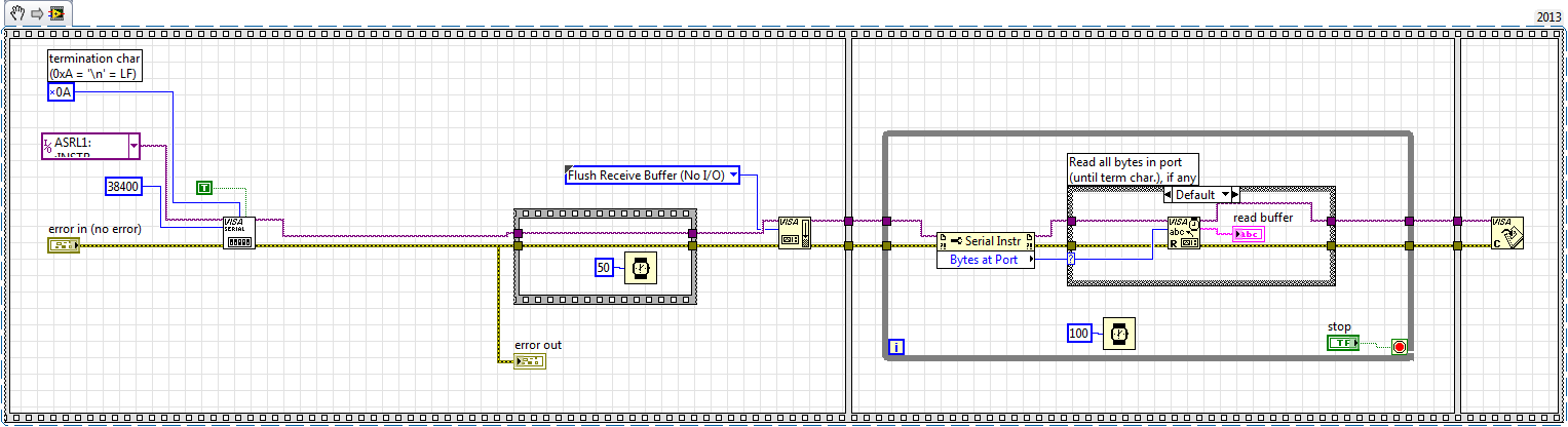
I'm reading a GPS signal via port RS-232 on a cRIO-9012. I enclose the simplified code.
The same code works when I run it on my PC (after changing the port) and transmit the GPS signal via a USB port using a series converter / USB. However, when I plug it into the port RS-232 on the cRIO and run it on my cRIO, the buffer seems to be in the wrong format, i.e. some information is read, but it shows some weired characters. Does anyone have an idea on how to fix this?
Thank you
It seemed that it was a hardware problem. The cRIO-9012 was probably too old/weak/slow to handle communications. Passed to 9022 and it works!
-
Align the two signals and measure the Phase Shift
Hello
I do an experiment in which I use the NI USB-6221 DAQ card. The jury is able to make 250 k samples/second. I want to measure two voltages in a circuit and find the phase shift between them at frequencies between 1 and 10000. First I ouputted a wave sinusoidal frequency variable through the Commission and applied to a test circuit. Then I used the Board to measure the two tensions consecutively (thus reducing the maximum sampling frequency at 125 k). I used the signals align VI and measured the two phases and then calculates the phase shift (VI attached in Phase 1). It worked well for the test circuit I built in which the phase shift went way logarithmique.20 degrees ~84.5 degrees and then stabilized. At frequencies above 5 000 Hz phase shift must have remained constant, but it varies more or less 1 degree. When the phase shift is 84.5 degrees, present a degree of variability is not particularly explicit. When I asked my program on the circuit that I really wanted to measure, the phase shift went from-. 5 degrees up to about 1.2 degrees. The change in the values of phase shift at high frequencies (> 3000) was environ.2 degrees. Given the small phase shift, this variation is unacceptable. Now I tried to use a sequence to each blood individually (increase the maximum sampling frequency to 250 k) and then align the two signals and measure the phase of each shift. When I use align it and re - sample Express VI to realign the two signals, I get the message "error 20333 analysis: cannot align two waveforms with dt even if their samples are not clocked in phase." Is it possible to align two signals I describe here? I enclose the new VI as Phase 2
Matthew,
I think I have an idea for at least part of the problem.
I took your program data and deleted stuff DAQ. I have converted the Signal on the chart control and looked then what was going on with the signal analysis.
The output of the Waveforms.vi line has two waveforms, like the entry. However, arrays of Y in the two waveforms are empty! It does not generate an error. After some head scratching, reading the help files and try things out, that's what I think is happening: the time t0 two input signals are 1,031 seconds apart. Since the wavefoms contains 1,000 seconds of data, there is no overlap and may not align them.
I changed the t0 on two waveforms are the same, and it lines up. The number of items in the tables is reduced by one. Then I increased the t0 of 0.1 seconds on the first element. The output had both greater than the entry by dt t0 t0 and the size of the arrays was 224998. Reversing the t0 two elements shifts the phase in the opposite direction.
What that tells me, is that you can not reliably align two waveforms which do not overlap.
I suggest that you go to 2-channel data acquisition and that it accept the reduced sample rate. You won't get the resolution you want, but you should be able to tell if something important happens.
You may be able to improve the equivalent resolution by taking multiple steps with a slight phase shift. This is similar to the way that old oscilloscopes of sampling (analog) worked. Take a series of measures with the signal you are currently using. The make enough average to minimize changes due to noise. Then pass the phase of the signal of excitement to an amount that is smaller than the resolution of phase of sampling rate and repeat the measurements. Recall that I calculated that for a 5 kHz signal sampled at 125kHz, you get a sample every 14.4 degrees. If shift you the phase of 1 degree (to the point/mathematical simulation), you get a different set of samples for excitement. They are always separated by 14.4 degrees. Take another series of measures. Transfer phase another degree and repeat. As long as your sampling clocks are stable enough so that frequency does not drift significantly (and it shouldn't with your equipment), you should be able to get near resolution of what you need. The trade-off is that you need to perform more measurements and may need to keep track of the phase shifts between the various measures.
Lynn
-
How to read the digital I/o using PXI-7813R?
Hi guys,.
I'm reading a digital signal by using one of the ports in the PXI-7813R. The 7813R has 5 digital ports or 39 lines for playback of digital data. I have connected a SCB-68 as the physical hardware interface for 'plug-in' a 5V adapter, which will act as my signal at the moment.
After you configure the PXI via MAX, I wrote two codes, one for my host pc and the other to control the FPGA through the host. But I think, I can have more complicated or completely gone in the wrong direction.
Any help in the drafting of these codes would be well appreciaetd.
Thank you, Anoop
You need the FPGA to sample the signal how often you expect the device to send the data.
If you write your data in the FPGA for the DMA, then on the side PC you just have to read the DMA. I like to think of the DMA as a queue. It makes it easier for me to understand how it works.
-
Why are there at - it such a delay, write and read a PWM signal to digital input?
Hello! I am trying to read and take action on a PWM signal. The equiptment I'll have access to: 9201, 9425 and cDAQ-9172 chassis of NOR.
That's kind of what I'm experimenting with now (I have tested with a device USB 6211). Someone at - it a better idea how to do that?
The problems that I encounter:
(1) it seems there be then buffering of questions?
(2) it takes too long.
My vi is attached.
Thanks in advance for any help you can give.
Also, in my final application, I will not have to create the PWM signal - this is just to test the acquisition currently.
Try to use functions DAQmx directly rather than the DAQ Assistant. They are a little more work to learn but are more effective. Your 6211 can generate a PWM signal in hardware, so use it (see examples of LabVIEW). Finally, of course there will be some delay in your code. You read to 1.5 k samples to 1 k/second, so each loop cycle will be 1.5 s.
EDIT: also, why you write 1 k samples and then read 1.5 k, both 1 k per second? This means that your output will not generate any signal for long periods of time...
Maybe you are looking for
-
iMac and yamaha md-bt01 wireless midi
Can I connect my yamaha P-95 keyboard with yamaha md-bt01 http://usa.yamaha.com/products/musical-instruments/keyboards/accessories/interfa CES/md-bt01 / to my imac?
-
I bought a program that designs business cards for my business and when I insert the disc in the tray on my laptop and close the drawer, nothing happens. I hear a clicking noise, but nothing appears on the screen. I also tried a movie in the model, a
-
Stopping automatically printer queue
I'm trying to find a solution to a problem printing. Whenever I have print a document or a Web page from any application the document stops automatically after the queue. The operating system is Windows Vista. The printer is a HP C5280. We have troub
-
My friend HP Pavilion needed the replaced HARD disk Seagate twice since buying 13 months ago. This time, we have decided to replace the standard Seagate 750 GB HDD with a Western Digital HARD drive 1.5TB. The WD HARD drive detects very well in inst
-
Printer all-in-one Officejet 5510v
My HP Officejet 5510v all-in-one printer fails to print from my computer, with an error message indicating that there is a jam. I tried to delete but cannot find any paper jam or carriage jam. I can scan, copy without problem. I can not even go to th