Production of rectangular pulses
Hi guys,.
I'm a newbie using Labview and what I ask can be easy.
I would like to generate rectangular impulses for the bits that I'm supposed to pass.
The bits are from a string. In my file, I convert the string into an array of int to show it, but I can't find the right way to create rectangular impulses of the table. I've seen on the web, the rectpulse function, but I don't know how to use it, there is no rectpulse block.
The results should be like this
Any help will be appreciated.
See you soon,.
Felipe.
PS: when you use the chain file must be:
1
0
1
1
0
or whatever the bits.
OK, I found the PPE function that suits me.
See you soon,.
Felipe.
Tags: NI Software
Similar Questions
-
Problems of sound with Satellite A500-13F
I bought a laptop Toshiba Satellite A500-13f and it's very good, but
My problem is that the * sound cut when you're listening to music and returns after 30 seconds * and also * a product of her pulse in the left internal speaker sound when the frequency of the high musical rhythms *.Please help, please
Hello
What are the strange sounds that even with factory settings, the sound cuts. I can advise you to update the audio driver no form page driver Toshiba but from here:
http://downloads.Guru3D.com/downloadget.php?id=2486&file=4&EVP=b3f15a2ab7c566c 9889ed65f5c7d5453
If she's not always you help, there may be a hardware - related problem.
-
Hello
We ordered the cRIO 9035 system with several Modules.
One of them is the NI9401.
I want to use this module to count the pulses of a flow meter.
In front, I am a beginner and started just look at a lot of tutorials and created Basic VI
- This Module has onboard counters, or is it only possible to use the 'material' - counters in the chassis through this Module?
I ask this, because I can put the Module via "Digital specialty Setup" as a counter.
If I do, it would be possible to simply create a while loop, place the channel on the inside and tie him to a digital item?
Or is the only way to count impulses (rising edge) to use VI as the 'edge counter VI' the example of VI? - My flow meter uses a Hallsensor and produces rectangular pulses at 40 Hz max.
It is absolutely necessary to use a FPGA or can I use a VI on the host computer?
We use 4 of these flowmeters (and many more sensors like Termocouples (NI 9211), solenoid valves (NI 9482) or a AKD-servomotor (NI 9472).)
All the measured data should be written to a file (for example, form exel).
Magnetic valves must be triggered if a certain number of pulses is counted.
Yet once, it is absolutely necessary to use a FPGA or can I use a VI on the host computer?
I know there is a lot to do and I have to learn a lot more, but I'm on it (its for my Masterthesis).
For now, the answers to questions about existing or not existing edge counter would be great.
Thank you for your support.
Greetings from the Germany,
Lukas
Lukus salvation,
Greetings from Munich (since it is a public forum, I am obliged to answer in English, in any case).
(1) when you use a cRIO you don't have a strict meter limitation (especially if you program the FPGA) for your digital inputs. Maybe read you something about that and that only applies to the cDAQs (because he (mostly) counters come from cDAQ chassis so they are more limited)
"If I do, it would be possible to simply create a while loop, place the channel on the inside and tie him to a digital item?"
FIX
"Or is the only way to count impulses (rising edge) to use VI as the 'edge counter VI' the example of VI?
I'm not sure which exact VI you are referring to, but on the FPGA you could implement a custom counter. That would work too.
(2) you can do two ways (Scan Engine Mode and FPGA)
If you write a master's thesis, you may be eligible for a greatly reduced price. The course Embedded Control and Monitoring (http://www.ni.com/training/embedded/) would be very useful for you:
Forderprogramme as research, training und Lehre - National Instruments Germany GmbH
http://Germany.NI.com/academic/training/programs/diplomandBest regards
Christoph
- This Module has onboard counters, or is it only possible to use the 'material' - counters in the chassis through this Module?
-
Hello
I'm trying to synchronize data between two different instruments using LabView.
A single instrument will work regardless (it can be integrated with LabVIew for various reasons) and the synchronization signal of this instrument, which I want to use (5.76 square pulse, 25 ns wide V, occurs aperiodically) is "extracted" (I made a breakout box and have the synchronization signal on a coaxial cable that I can plug into anything).
I want to take this synchronization signal and use it to trigger an event in LabView (the second instrument is controlled with LabView).
I had hoped that a USB 6501 would be able to go around, but I realize now that he can't see a signal that is so short (I think).
So, what should I do? How can I make LabView 'see' a such narrow pulse and use it to trigger an event?
In summary:
- Have digital signals from a piece of hardware on a coaxial cable - 5.76 V rectangular pulse, wide 25ns, occurs randomly nut not more often than every ms
- Want to get the digital signal into my PC and LabView where I use this signal to trigger an event (in this case, to start an event of data acquisition on a different piece of hardware that is controlled with LabView)
- I'm using LabView 2013 64 bit, Windows 7 x 64
- I was hoping to use NI USB 6501, but I'm not sure it's possible, given that the impulse is so narrow
- Picture of the sync signal as seen on a scope is attached (note there is a tiny little ring that will not present when I fix the cable)
Thank you
Sabrina
Hello
You could use a flip flop to intercept the signal. Do not attach the pulse but the front. You can read the regular output of the scale with any hardware DAQ (digital or analog) and use the same DAQ hardware to reset the flip-flop.
Kees
-
Precise triggering voltage input and output generation in the DAQ Assistant
Hello
I wonder if anyone has come across a simular problem with the synchronization of input and output voltage. I use a box 11 LabView and NI USB-6259. I have been using the DAQ Assistant to configure the input and output channel. In particular, my task is to generate a single rectangular "pulse" as the output voltage to drive a coil and once the pulse went to get a signal from a sensor of magnetic field and get a power spectrum. This means that the order and the time during which the DAQ Assistant is used is extremely important. For example, the output voltage channel must be opened first for 2 seconds. Subsequently, the channel of input voltage must be open for 1 second, in which the sensor signal is obtained and post-processed. Only after these tasks are performed in this order he can can be repeated in a loop until the experiment is over. I don't know how to trigger data acquisition assistants (one for entry) and the other for the voltage output correctly. Y at - it a trick?
See you soon
Michael
Hi Dave,.
Thank you that I wired the error strings but the timing issue was unrelated to it. In the DAQ assistant, I simply had to choose the continuous aquistion of the 'samples' methods 'N-switch' for input and output voltage and all works fine now.
Thanks again
Michael
-
How to set a start and a trigger digital stop conting number trigger signals
Dear all,
This is an application for the acquisition of data that I don't know how to set triggers. The trigger signal is a sequence of rectangular pulses. A plot of X - is necessary. The interval between signals start of X are the same. So, I need to count signals trigger to know the value of X. And the value is analog signal. If the trigger interval corresponds to dx, my range of measurement is lying will begin with the rise of the m trigger signal - th with X = m * dx, then it stop at the rising edge of the signal trigger of the n - th with X = n * dx.
But I don't know hot to make this trigger + counter. The attachment shows a schematic representation of the measure. Can anyone help?
Thanks in advance.
Best,
Jiangjun
Set the meter to measure the pulse in continuous or over mode according to your requirement.
Use the source of synchronization as the trigger pulses & configure rates at least 100 times rate of relaxation. Then compare the value count against'm & n' & generate the impulse on the PFI lines or the port pins.
I guess you know m & n values.
The other way is to configure to tell it to count the no. rising edges. Then compare this number with'm & n' bones & generate the impulse on the PFI lines or the port pins.
-
Dear users of Labview,
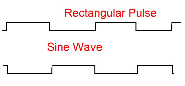
Im having trouble with this Modulation of Amplitude. What I want is to change the Amplitude of a sine wave with a rectangular pulse as follows (see figure):
The sine wave of the morning will be the entrance to my DAQ hardware. I thought that this is a strange modulation because I found no info on this type of modulation (only refer to the sine-by-sine modulation).
Any help on this issue would be greatly appreciated

Best regards, Dennis
Amplitude modulation is just multiplication. If you multiply your sinusoidal carrier by amplitude modulation signal, you will be there. There are a lot of subtleties, but it's the essence of it. The wikipedia article is a good overview and has some nice graphics to explain it. In LabVIEW, you can multiply two arrays as easily multiply two numbers. Just them wire for the primitive multiply.
-
The gateway configuration GemFire 7.0.1 via Java APIs is unable to successfully deploy
I followed the instructions here: (WAN) multi-site Configuration.
I have been unable to deploy a gateway and according to me, Miss me him a little bit of configuration, but I can't identify what it is.
# loc1.properties
jmx-manager-port=1899
mcast-port=0
remote-locators=localhost[11045]


distributed-system-id=1
gfsh start locator - name = loc1 - port = 11044 - properties-file = loc1.properties
# loc2.properties
jmx-manager-port=1999
mcast-port=0
remote-locators=localhost[11044]


distributed-system-id=2
gfsh start locator - name = loc2 - port = 11045 - properties-file = loc2.properties
String license = "== omitted valid WAN enabled key ==";
String serverName = "node1";

CacheFactory cacheFactory = new CacheFactory();
cacheFactory.set("name", serverName);
cacheFactory.set("mcast-port", "0");
String workingDir = String.format("c:/software/ssw/%s", serverName);
cacheFactory.set("license-working-dir", workingDir);
cacheFactory.set("deploy-working-dir", workingDir);
cacheFactory.set("locators", "localhost[11044]");
cacheFactory.set("license-data-management", license);
cacheFactory.set("distributed-system-id", "1");
Cache cache = cacheFactory.create();
cache.setIsServer(true);

CacheServer cacheServer = cache.addCacheServer();
cacheServer.setPort(30303);

String gatewayName = String.format("%sSender", serverName);
RegionFactory replicatedRegionFactory = cache.createRegionFactory(RegionShortcut.REPLICATE_PERSISTENT_OVERFLOW);
replicatedRegionFactory.addGatewaySenderId(gatewayName);
replicatedRegionFactory.create("TestRegion");

cache.createGatewaySenderFactory().setParallel(false).create(gatewayName, 2);
cache.createGatewayReceiverFactory().setStartPort(12000).setEndPort(12009).create().start();

cacheServer.start();
Each member starts and runs but when inspecting via "list gfsh gateways" I have the following message:
[warning 2013/11/15 13:56:50.148 CST loc1 <RMI TCP Connection(3)-172.20.121.109> tid=0x56] (tid=11 msgId=11) Errorjava.lang.Exception: node1 is an invalid member name or Id
  at com.gemstone.gemfire.management.internal.beans.DistributedSystemBridge.validateMember(DistributedSystemBridge.java:694)
  at com.gemstone.gemfire.management.internal.beans.DistributedSystemBridge.listGatewaySenderObjectNames(DistributedSystemBridge.java:1218)
  at com.gemstone.gemfire.management.internal.beans.DistributedSystemMBean.listGatewaySenderObjectNames(DistributedSystemMBean.java:344)
  at com.gemstone.gemfire.management.internal.cli.commands.WanCommands.listGateway(WanCommands.java:603)
This message is incongruous with ' gfsh describe config - Member = node1':
gfsh>describe config --member=node1
Configuration of member : "node1"

JVM command line arguments
-------------------------------------------------
-Didea.launcher.port=7542
-Didea.launcher.bin.path=C:\software\ide\IntelliJ
IDEA
12.1.4\bin
-Dfile.encoding=UTF-8


GemFire properties defined using the API
.................................................................................................................................
deploy-working-dir                       : c:\software\ssw\node1
distributed-system-id                    : 1
license-data-management                  : === omitted ===
license-working-dir                      : c:\software\ssw\node1
locators                                 : localhost[11044]
mcast-port                               : 0
name                                     : node1


Cache attributes
.................................................................................................................................
is-server        : true


Cache-server attributes
. port                 : 30303
Has anyone tried to get a bridge linking purely Java API?
Thank you
Jeff
Jeff,
I appreciate you are trying to help. I expect to have a setting that I forgot. Your suggestions were valid and I have test again each of these this morning. I think I've identified the problem and it isn't really a problem code, setting issue or a question of GemFire. I think that our network of local offices has a particular configuration that affects GemFire in a unique way.
In my test, I used localhost as the address for locators and remote control-locators. I changed to be my explicit hostname and I do not see the error longer. I am able to inspect bridges via gfsh and start them. FYI: I witnessed a different symptom with the new product of the pulse. When you try to deploy the war impulse locally I be watching only partial functionality. The application of impulse load but could not inspect the data nodes, but I could see the locators. I played with each of the possible combinations (ip address, host name, localhost, qualified domain host name) and the only way I could solve the problem of the impulse was to use the host name. It smells the same number of local network.
I'm working on a Windows desktop computer and use an active Windows with DHCP domain controller. Production deployment is on RHEL and should not encounter these problems.
Thank you
Jeff
-
A Message in the box 1. "Message agent wants to use the 'Local products' kenchain. "is appearing on the screen and ask for Keychain password password. This started after I changed the password of Apple resulting for the purchase of a new iPhone.
My iPhone 5 has been damaged and the screen was not visible. As a result, I couldn't open the iPhone. I bought 5 s iPhone and when I got to connect with the iCloud
I remember the answers to security questions. The seller must change the password and enter new answers to security questions, I did. This happened in Bangalore. When I'm home in Ernakulam, Kochi (India), where I has the Air of Mac, Ipad and my wife had another iPhone and laptop computer Dell, these problems began to come up on the screen and blocks the screen.
Four Messages are appearing: the first is on the top.
Other messages are:
2. ' cloudd wants to use the kenchain 'local products '. '
appearing on the screen and ask for Keychain password password.
3. ' com.apple.iCloudHelper.xpc wants to use the kenchain 'local products '. appearing on the screen and ask for Keychain password password.
4. ' cloudpaired wants to use the kenchain 'local products '. ' is appearing on the screen and ask for Keychain password password.
It of an upheaval and please suggest how to solve this problem
Hello remy!
I see that you are either prompted by iCloud Keychain with various alert messages. I know it's important to have iCloud Keychain works correctly and I am pleased to offer you an article that should help you. Please follow the instructions in the following support article:
If your Mac keeps asking for the password in the keychain
Thank you for using communities of Apple Support.
See you soon!
-
at the same time production and measuring the pulse
Hello everyone,
I'm generates a pulse for specific time. Now, I want to measure within the same daq card. I've done Vi for him but he has an error. I have USB daq-6343. I enclose my Vi here.
The problem is I am able to get pulses generated at PIN 6 PFI but reading Vi watch time-out error.
I plugged the wire between PFI 1 pin and PFI 6 pins on the DAQ card.
So please suggest me what to do to eliminate this error.
Thanks & best regards,
I just looked at your original vi, I had looked only at the most distant (corrected) a previously. I don't see a good reason to read timeout error you have immediately. Record of an error timeout on your attempt reading suggests that the code was executed without error so far, including the beginning of the generation of pulses. That would leave wondering on physical cable connection or possibly some undesirable side effects caused by your cleanup code when you three States a PFI lines.
The other issue was my suggestion to leave DAQmx Timing.vi outside of the configuration string entirely for cases like this where you only want to build a single pulse. To be honest, it's a habit & practice I adopted a long time ago. I thought one of the reasons was that the finished pulse trains required a minimum of 2 samples. A bit of test code showed me that it isn't true, if my memory tells me there was a time when it * used * to be true. I don't remember if I have errors or if the task has chosen to generate 2 pulses with just a warning, or something. I just remember that, while he was working on a module that was supposed to be able to produce any number of pulses from 1 to N, I found that I wasn't actually able to support the case of 1 pulse by asking just 1 sample over sample mode.
* Anyway *, the other reason to avoid sampling over for a single pulse mode is that in the past, this would consume actually 2 counters on DAQ cards. Generated the pulse (s) while the other was a help that triggered the first to control the number of generated pulses. It was unnecessary as you could * also * generate a single pulse leaving the DAQmx Timing.vi out of the config, a method that used only 1 meter.
X-series cards (like yours) don't consume over 2 programmable counters of the user to generate finite pulse trains, so the lesson I learned a long time ago and was trying to convey is perhaps not so important in your case. I recommend it even if you know that you will always generate a single pulse, simply because he considered the standard way to generate a single pulse (as seen in examples of navigation).
-Kevin P
-
HP Pavilion 15 Gaming Notebook: computer laptop lid/top shows the light rectangular patch of light
I bought my laptop on December 31, 2015. Computer laptop lid/top (surface behind the laptop screen) allows you to travel light screen in there because it was very translucent and is clearly visible and resembles a rectangular patch. I don't know if it's a design flaw with many HP 15 mobile games or if it is specific to my laptop?
I took the screenshots via lightshot and downloaded more than diagnosis:
I tried to contact HP for literally days now and they are online 'support' (Webchat and phone call center) is ALWAYS offline... I don't know if I would return it instead I bought (Currys/PC World).
Hi @trdjy,
I brought your question to the attention of a team within HP. They are likely to ask for information from you to get your information or product serial number. Please search for a private message from a contact HP identified. Also, remember not to publicly post information and series numbers.
If you are unfamiliar with works as a private of the Forum messages, this post has instructions.
http://h30434.www3.HP.com/T5/first-time-here-learn-how-to-post-and-more/how-to-check-your-messages/TD-p/3547355 -
Hello
I use a mx-acquisition of data (NI USB-6211) and I would like to use it to generate a pulse of digital modulation
that is triggered by an analog input signal. The input signal is a pulse of squares analog modulated
What is almost periodic. It's because of my set up, and I can't do anything with it. I would use the
before the edge of this signal to trigger the production of a digital pulse signal modulated (0-5 V). My
problem is summarized in the figure given in the annex. I would also like to have the possibility of
Configure the 'backwardness' and the term of "TAU_LED", while the VI works.
I have looked at several examples of instrument OR meter generation, generation of PCI I / AO, but doesn't
not managed to solve my problem. Does anyone have an idea of how start with my problem? Are there
No matter what example VI that I could start to change?
Thanks in advance,
Gregory
Hi Gregory,
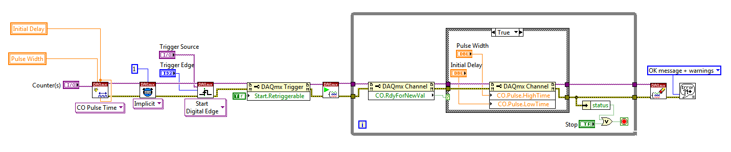
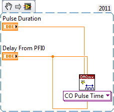
Sorry I forgot to mention: the Initial delay applies only to the first impulse of a redeclenchables generation. Every subsequent impulse will use low time as the Initial delay. I agree the behavior is not very intuitive (our latest guidance of series X actually supported an Initial period to allow on property Retrigger), but it is described in this knowledge baseand should also be mentioned in the DAQmx help.
As you generate just a single pulse, I would recommend simply connecting the Initial delay and at the entrances of low time to the same value for each pulse will be delayed further.
Exit tasks ongoing counter currently supports DAQmx writing. However, the finished generations or simple impulse are not. However, you should always be able to get the behavior you need with a property node DAQmx. The current solution on the series E/M is:
Again, this is not the most intuitive, but I checked that it works on my 6210. After writing a new value in the software the pulse will be updated on the 2nd trigger. Attached is the code stored in LV8.2.
Best regards
-
Control the time times of high and low of trains of pulses in C++
Dear team of support of National Instruments,
Here's what I have so far:
I was able to generate the number of pulses (a pulse = a rising edge and front descending one) that the user has indicated via the GUI I created in Visual C++ 2008.
I use DAQmx 8.6.
I use the DigitalSingleChanWriter (hopefully, that's what it's called).
I use for the synchronization of the sample, on request. I tried to use all other types of calendar but I always get a DAQException run the error that says I can use only OnDemand calendar.
OK, so here's the problem:
I have a USB-6008-6009 card connected to an oscilloscope. I know that the connection is correct, otherwise nothing would appear. However, if I send say... 6 impulses, the delay between the first rising edge and the first falling edge is dramatically different and then the second and the third. If I return my samples, I get an assortment of new and totally random times. So finally, my question is "Is there a way to control the time of a great time and a bit of time?"
I use a Compaq 2003 lap top, what is worthy of the rubbish heap. I'm not to blame on this right away as problems that will not solve the problem at hand. Although I understand if it's actually the problem for random times, but I would still have no way to control the time themselves.
I hope that I don't have drug it too long, but I decided that distribute information on would be better then just a few tid bits.
Thank you for support, that you can offer,
Daniel
OK, so I just returned from the lab, and this is what I got:
I was able to control the time at the time of the high and low by using the "WriteSingleSamplePort" of the DigitalSingleChanWriter method.
I put it in a loop that repeated many times that the user wanted impulses.
At the beginning of the loop, I used a delay function that I wrote and delayed for a time given and then a pulse with a value of 255 and then delayed again and a pulse with a value of 0. And then restarted the loop.
In the end, it works.
Of course, I have another question. I kept reducing the amount of time between two pulses (1 s, .5s, .2us and so on). However, once I have diminished the time of secondes.01 or a millisecond, the pulses on the arrested oscilliscope becomes smaller. It seems that past 1 millisecond Board USB-6008/6009 is unable to deal with the exigencies of the moment. Or else the computer trash part on that I cannot deal with the exigencies of the moment. But I believe that the Council is not at fault because it was designed for this exact sort of thing, could you tell me if there is no limitation to the Commission which prevent production of pulses in or within a period of 1 millisecond. Thank you very much.
Thanks for all the help,
Daniel
P.S. I'll stop you buggin with big messages that I promise you.
P.P.S. If someone wants to see my source code for their own project, I'd be more than willing to share. Please email me or leave a message here.
-
Create two independent signals and a pulse train with NI USB-6259
Hi all
I'm new to the forum, I searched but I've found no info about it.
I have recently set up a vi that is able to generate from an NI USB-6259 case two different signals in frequency, amplitude and phase (see attachment).
To do this with each cycle of the memory buffer size is changed accordingly for frequencies in order to see a whole number of periods and, thus, having not leak in the generation (or breaks).
Now, I would like to generate a pulse train at a frequency that is an integer multiple of the frequency of the input signal (not the 50 Hz one).
The resulting frequency of the pulse train could be changed on the fly (or at least be updated at each new round of vi).
I'm stuck because I have already said that two analog output channels and I want the pulse train so that a digital camera for my Board (channel PFI) output, you have any ideas?
Thank you very much
Alberto
PS. the vi is "program generazione.vi" but you must first install "signal.vi production".
Hello
It is a simple .vi which generates a configurable, buffered pulse train dynamically. I also want to let you know that with this type of advice (DAQ), it is impossible to update the output in real time. You must be careful because the time between you use "DAQmx Write" and the output effective physical change not IS NOT FIXED.Kind regards
Matteo
-
Generate a pulse trains finished redeclenchables 2 of different duration using 2 counters
Hello
What I want to do is to generate at the same time 2 redeclenchables finite pulse trains using my PCI-6221.
To be more clear, take a look at the attachment.
Relaxation is in/dev/PFI0 for example and I want 2 impulses/dev/ctr0 and/dev/ctr1 at the same time.
I can easily produce/dev/ctr0 or/dev/ctr1, but never/dev/ctr0 and/dev/ctr1 at the same time.
It sounds feasible that I want to achieve?
Thank you very much.
Adrian
I couldn't open your VI as I use LV 2011 on this desktop computer.
However, you must just on delay initial as well as the low time some delay desired with respsect to PFI0 on the ctr0 task.
Other NI DAQ products behave differently, but the 6221 uses "shortly" for the initial delay for each output reset after the first.
Best regards
Maybe you are looking for
-
Hey,. So I was remove my photos using cmd and return back, who moved to my trash, but when I try using the same button to remove them from my recycle bin so they are gone for good. He moves right in my photos. People say there delete button while fil
-
How can I connect my nokia 6600 and a laptop via bluetooth
How can I connect my nokia 6600 and a laptop via bluetooth to send information? This is so complicated. I have this suite of pc to 6600 installed in my laptop and I can't connect it. Can someone help me?
-
Passport for blackBerry charger
Hello! I can't load my blackberry with original charger. How can I me difficulty the original blackberry charger? Where should I send? Thank you
-
BlackBerry Smartphones can not remove two emails - HELP
I have a TOUR 9630 for about a year and was able to remove e-mail messages without problem... with the exception of two who will not erase! I tried everything and I can't delete these two messages for some reason any... I tried to remove it from my l
-
Adapter HP Pavilion TS of network Sleekbook 14
Greetings ~ I installed Win 7 Professional on a HP Pavilion TS 14 Sleekbook, number 14-f023cl product. This laptop has connection to our network wireless prior to this installation. Now, there seems to be no network card or the network card is unreco