PT-100 resistance measurement
Hi Raghunathan,
You can find the following links to help you:
Take measurements of temperature with the RTD: practical Guide
With an RTD or thermistor temperature measurement
In addition, it would be useful if develop you your condition a little more each time you post.
Tags: NI Hardware
Similar Questions
-
with an average of 100 consecutive measurements below a threshold value
Hello
I just started programming labview. I'm having difficulties with just this very simple programming code. I was breaking my head all night. I'd appreciate a quick response.
How can I make a code that would allow an average of 100 consecutive measurements which are below a certain threshold value in labview?
Thank you.
Try the joint. The key is shift registers-(blue) integer is a counter of deca thresholds measures and it returns 0 if there is a measure above threshold the result is saved whenever the counter is greater than 100 (indicating > = 100 consecutive values of 'good'). This also prevents internally while loop and outer loop causes the records to shift to reset. I added a function to "define the position of the file" then the values will be added rather than overwrite the file. You will probably need to insert a carriage return in the string that is written in the file so that the values appear on separate lines. I also changed your data types of DBL - they were I32 (integer) that doesn't seem to jive with your indication that you take analog action.
-
resistance measurement but value is not constant
IM using the program attached in the image below, but the value of the resistance of the resistance measurement is not constant. Also I don't understand what are a source of excitement and value. Also it is attached a picture of the items Im using.
-
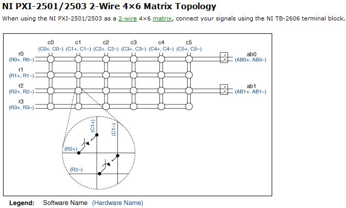
Resistance measurement using PXI2503
Hi, I am looking to understand how PXI-2503 measure resistance of 2-wire matrix 4 * 6.
and I tried several different configuration on my board but I couldn't receive the correct value of the resistance.
Software:
I use the example of LabView8.5 (niSwitch DMM Scanning.vi synchronous switching)
My scan list of entry (c0-> r0) under the switch
between 10000 and resolution 100 m under the DMM
Material:
I tried several set upward,
1. I put a resistor between C0 + AB0 + and r0 + AB0 -; and - c0, r0 - connect to GND, (this configuration gave me some graphics but no resistance)
2. I set the resistance between c0 +, r0 + and AB0 + (they connect) and c0,-r0, AB0 - (but it gives nothing.
my setup is bad? why I could not receive any resistance...
Thanks for any help
Hi Newer104,
The problem may be that the analog bus relay is not closed. Please refer to the following image and note that the ab0 relays must be closed to create a path between the rows/columns and the analog bus.
If I understand correctly, then I recommend placing the resistance between c0 + and c0 - and create the entry list of scan to the following address:
R0-> c0 & r0-> ab0;
Let me know if this solves your problem. Best regards!
Chad Erickson
Switch Product Support Engineer
NOR - USA
-
resistance measurement USB-6009
Using the DAQ 6009 to measure the resistance resistance?
Sure. You just need to know what you're doing. In addition, it depends on what precision you're looking for.
-
Measures of constraints with the NI 9219
Hi all
I join this forum and I need bit of advise on measurement of deformation using NI 9219 with lab view.
I followed the procedure and settings to configure a virtual channel to strain under global virtual channel of NI DAQ mx.
I need some clarification on strain gauge measures:
1. If I use 1 quarter bridge configuration should I NI 9219 completion resistors?
2.i have ordered strain gauges, but I can imitate the calculations of strain with labview gauge using a variable resistor instead of active Gages? as I understand, it's strain gauges to change resistance when the force is applied.based on this notion if I use a variable resistor on one leg of wheatstone bridge and plot the data? all I want is to play with lab view until I get the real strain gauges. (will take a week to get deleivered)
3. affecting the internal Vex I think that I will not need to apply any voltage to the terminals of the bridge as the strain of installation window.i would just need to connect to the ends of the stone bridge of wheat to the PIN number 3 and 5 in the comment of 9129.please OR who...
I have to really thank and appreciate all of you for taking the time and reading/commneting on my post.
Kind regards
Ali
Hi Engr_tech,
9219 a resistance integrated half-bridge completion, but for quarter-bridge measures, it must rely on resistance measurements 2 son. It does not support the measures of quarter 3-wire bridge. I'm not familiar with the help of a variable resistor instead an active gauge so I can't comment on that. Looks like your #3 idea would work, although I'm not 100% certain. It will be unsupported, but it could work.
-
Read a resistance of the diode by vs NI USB multimeter
Hello
I read a resistance of the diode at some entrances to supply voltage
and I found that
to 0.2 V
the value of resistance by NI USB-6212: 200 ohms
the value of resistance of meter: 2 kohm
0.5 v
the value of resistance by NI USB-6212: 500 ohm
the value of resistance of the multimeter: 5 kohm.
Could you please let me know why the values are different by 10 times?
Thank you.
No - we can't measure the resistance in this way.
To measure resistance, you normally spend a current known and then measure the voltage. A DMM will be repeated by generating a little known current and measuring the internal tension. If you provide an external voltage thus, DMM internal resistance measurement will not work.
For the LabVIEW - The USB-6212 can measure the tension. If you want to measure resistance, while the unit is plugged, you need to know/measure current (for example through a shunt resistance) and the tension and then do R = V / I for the resistance. I don't know what the argument of type 6212 if you try to perform a measure of 'resistance', as it is not a source of internal current.
Oh, I thought that this all seemed familiar - here's a similar thread: https://forums.ni.com/t5/LabVIEW/daqmx-resistance-measurement-6251/td-p/3267084
-
Help with measurement registration
Hi all
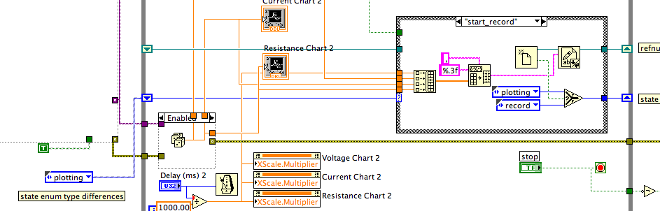
I try seizes a sourcemeter Keithely voltage/current/resistance measures and their trace on the cards. There is also the possibility to record the measurements by pressing 'save', which then encourage the user a path name. "After the" record "button again, the file is saved and closed. Throughout the process the file open, save and close the file, the measures must be plotted on maps without interruption.
I used a model of State machine, with the value of the 'save' button as input to decide state transitions, used in a door "select." However, when I run the VI, state transitions does not happen, the suspension of the execution and probe the value of the button as its production yields remains the same regardless of the State of the button.
I have set the operation of the button "change when you press on.
I know it's a common task, but I'm pretty stumped on how to solve this problem. The VI file is attached, any pointer is appreciated.
Thank you
Typedef enum will solve the problem of names. Once that all sources (controls or constants) related to the State line in all cases and outside the loop are all copies of the same typedef, returns the names.
What's happened is that you have changed one of the enums or created a new. He had a different type of data. Yes, it was still an enum and always produces an integer U16, but because the items were different, it was considered as a different data type. When two different types of data are connected to the wire goes to the terminal selector, the structure cases trying to find the "common denominator", in this case an integer U16, but not the enum.
I converted the enum constant, you had with 'save' and other values for a type of def and copied several times. When I replaced all other State enums with this def enum type, the names are returned.
Lynn
-
Specification OR ELVIS II + DMM
Hello
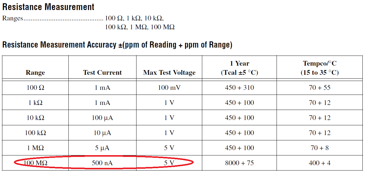
Recently, I use NI ELVIS II + for the characterization of the sensor due to the measurement of the resistance to 100Mohm.
However, I found the spec said 100Mohm measurement can be done by using max test 5V voltage source and current source internal 500 nA? Using Ohm's law, 10Mohm has proved to be the maximum extent?
Kind regards
Sin Chong Yung
Hello
DMM NI ELVIS II has a permanent entry of 11 MOhm resistance. For the measurement of the resistance, the device under test (DUT) is assumed to be in parallel with this 11 MOhm. The ASE resistance is calculated from this nonlinear relationship by measuring the test whereas calibrated current excitation voltage and parallel resistance.
For example, a 10 MOhm DUT measured in the interval of MOhm 100 with a current excitation nA 500 would show all (11 M: 10 M) * nA 500 ~ = 2.6 V.
With a 100 MOhm DUT, the test voltage would be of about (11 M: 100 M) * nA 500 ~ = 4.95 V... right against the limit of 5 V.
Enjoying a beautiful, the test voltage is (11 M) * nA 500 ~ = 5.5 V that is larger that the 5 V limit and is detectable in the 'OPEN' in the software.
NI ELVIS II DMM design was obtained from an other DMM with the input resistance is selectable (11 MOhm or > 10 GOhm). In this case, the excitement of nA 500 could be used in conjunction with the 10 GOhm input impedance to give 10 MOhm resistance measuring range. Since the resistance of the DMM NI ELVIS II entry is fixed, there is a separate offer 10 MOhm.
I hope this is useful,
Charles Y.
National Instruments
-
Hi again,
I have another question regarding the 4071 dmm and autorange. When you use the selector/DMM express it is not possible to select autorange and 7.5 figures? Is there a limitation in this sense?
Thanks again,
Concerning
Hi Nitad,
By default, the automatic selection is set to a resolution of 5 1/2 digits and can not be changed in the Express vi. However, the automatic adaptation to 7 1/2 digit can be accomplished by manually configuring the DMM for the settings of 7 1/2 numbers in the DMM measurement by default using DMM. You will need to use the lower level (instead of the Express VI) screw to set up your measurements for 7 1/2 digit. For reference, I've listed 7 settings 1/2 digits, you need to set up explicitly.
Opening time: 100 ms
Auto zero: on
ADC Cal: on
Rejection of DC of nose: strong weight
Number of averages: 4
You can look through the viewfinder of the example to find an example that would be a good starting point to change your code to auto-gamme to 7 1/2 digit. In the example Finder folder, I would use the example in: material input and output--> modular instruments and devices--> NOR-DMM (digital multimeters)--> measures only--> resistance measurement (2 or 4-wire) .vi.
When you use 7 1/2 digit in the automatic selection, your total measurement time will be long. Each measured range is 7 1/2 digit, so when the DMM will analyze different ranges to find the optimum range, the total time can be long fast.
Cheers!
Brandon G
-
How to connect the chassis cDAQ for strain gage
Hi, when I read the guide of the extensometer of wiring on a chassis cDAQ (http://www.ni.com/white-paper/7130/en) I found confusing fig 10 .
What are the things between the chassis and the extensometer?
The three wires go only one channel of the cDAQ chassis? (in Fig 10, on channel 0?)
Why there are four terminals (CH + EX + QTR EX-) on the strain gauge, but there are only two wires coming out of my extensometer? What should I do?
PS. I have a USB-4431 cDAQ and a Vishay extensometer (http://www.vishaypg.com/docs/11297/250lw.pdf)
Thank you very much!
Elly
ZSH2010,
The 9219 will work. You will need to use a measure of Bridge 2 son resistance measure quarter vs. For more information about how to use the 9219 for 2wire resistance measurements, take a look at the 11 and 15 of the document specifications page
http://www.NI.com/PDF/manuals/372407a.PDF
It will be slightly less accurate than the quarter for the 9237 bridge accessory, but still needs to do the job.
Kind regards
-
Place HP 34401 in Local with GPIB-USB-HS Mode
Hello
I'm using LabVIEW 2010 SP1 to control the 34401 HP with the NI GPIB-USB-HS device. I use I/O built-in 34401 instrument drivers.
If I plugged in everything, the 34401 will be immediately placed in "Remote" mode when I run my software. However, I would like to be able to use LabVIEW to force the 34401 to 'Local' mode Unfortunately I could not find a way to do this. I tried Close.vi, but has no effect.
Here are my planned operation if it makes things clearer:
- Launch the software
- Initialize the 34401
- Place the 34401 in the 4W resistance measurement mode
- Pass the 34401 in "local" mode so that the end user can adjust a knob until the desired resistance is obtained while seeing the value of the resistance to change on the 34401
- Re-initialize the 34401 when I need to switch to another measure
If not, is there a way to get the 34401 to permanently display how it is taken in remote mode?
Best regards
Ian Williams
Linear Applications Engineer
Product precision linear, and remote sensingThe feature I mentioned does exactly the same thing except that you have to do this awkward analysis of the address. It's a VISA function you have just used the search button to find (and have lit context-sensitive help) to obtain explanations of what he does.
-
given high-frequency sampling one at a time
Hello
I'm using LabView 2011 for resistance measurements. The express vi DAQ assistant is placed in a while loop and it acquires 1 sample (on request).
Each sample is acquired, it is compared to a set point. If the resistance value is greater than the set value, a task is executed. If this is not the case, no action is taken.
Now, I would like to increase the frequency of acquisition of say 5 kHz. As before, I wish the DAQ to give each value because it is acquired and compare it with the desired value. However, only one point acquistion is limited by the speed of the while loop (which does not exceed a few Hz per second when I use the software-timer.) If I use 'continuous samples' at 5 kHz, data acquisition does not give these samples one at a time. It seems to acquire until the buffer is full and then released several samples at a time. It is therefore impossible to compare with the set value.
Is it possible to get data at a high frequency and do compare to the set value, one at a time?
The code is simple enough to do this.
But the problem, it all comes down to how fast all of the other code in the loop takes to run.
The first problem is that you use the DAQ Assistant, which provides a lot of extra load in the loop, especially if you don't set it up properly. (And we can't say because no code is set to look at us.
You should try a real code DAQmx where launch you acquisition continuous samples before the loop, acquire exactly 1 sample in the loop. Then close the DAQmx task once the loop ends. See if keeps.
Why do you need to do this? Note that all instant Windows might decide to fly a second or two and go and do something else like a virus check. If you need at that moment (how exactly do you need that?), then Windows is not the right system for this run.
-
Components for the Acquisition of data for a Sub miniature sensor
Hello
I'm looking to acquire the data of two simulatneously cells (T4 - 100 L Measurement Specialties ELFS) load Sub miniature. The FS it out 100 lbs to 2.83mv / lb. I already have LabVIEW 8.2 and have acquired data using an analog I / 0 but my signal was weak compared to the noise in the system. I am a high speed data capture because the application that I use has an impact.
My question is: what the amplifier signal conditioner and the DAQ combination would be the best for this aplpication?
Thank you
Scott Kramer
Hi Scott,.
Welcome to the forums EITHER! Looks like you might be interested by the 9237 bridge and strain measurement Module. The 9237 comes in a USB, Ethernet, or Wireless channel, or as a stand-alone module for use with a cDAQ chassis. The 9237 offer a 50ks/s/ch sample rate, up to 10V of internal excitement which should reduce the noise from your system. Based on what you mentioned, it's the product I would recommend - you can find the manuals on the links above to verify that it meets all your needs. There are additional specifications that you need?
-John
-
How to extract an element of a table 1 d product within a while loop
Dear all,
IM new to labview. I got the task to create the program for the route of some settings in my lab. I created a program to interface sourcemeter keithley 2636b that will help me source voltages in a range and get the current and the resistance and ground them. I used a simple while loop for this. My problem is the following. I need t extract the nth element of the array created for resistance after each measure and store it in an array. I need to make a resistance measurement several times one after another and save the nth element each time these individual tables and push it into a buffer so that I can trace elements in the buffer against a setting (this is called a measure TLM). I tried several methods. Some nice guy / gal had posted a solution using the loop to retrieve an item. Its doesn't work don't not in my program I need to use a loop in my time loop and it gives is not the correct value. Kindly advice. IM in a lot of pain. Help!
And indexing does not work?
Why don't you check out 2D paintings and the bays of clusters and try to make your 'readable' with that code?
Also there are many resources available online:
Introduction of 3 hours
Introduction of 6 hours
Bases LabVEW
Paced self-study for students
Self Paced Training beginner to advanced, required SSP
LabVIEW training Wiki
OR learning
Getting started with products OR
Maybe you are looking for
-
I have a mid-2014 13 "MacBook Pro retina and El Capitan running - my fan has stopped working and it gets very hot. It just started today. I noticed, that he had been getting hot in the last months, especially if I watched the video on a browser in ad
-
How to upgrade Firefox using a dial-up connection
My connection does not allow me to download the update for Firefox - connection is disconnected after several minutes. How can I get an update?
-
I looked in the box, he had no serial number, but it has a sticker and said the SN: n ° 81MOAD204352 and part: 90_MBB790_GOAAYOKZ if you are a Microsoft support worker please help me.
-
PSC 2410 - How do I clear the fax report
I have a HP PSC 2410 printer all-in-one. I can not find how do I clear the fax report. Thanks in advance.
-
Can someone help me fix this problem