put hardware buffering discipline analog output
Tags: NI Software
Similar Questions
-
DAQmx: Analog input directly to the analog output at the hardware level
Hi all
I searched for a while, but I couldn't find any suitable implementation for what I'm trying to do. A person where I work introduced me to an interesting challenge. Is there a way to set up a DAQmx task (or set up otherwise an MIO Board) to route an entry directly to an output to the analog analog hardware level? You may be thinking, "why the hell would you do? To reduce the electrical complexity, a colleague would like to concurrently read an entry while 'reproduction' of its signal on analog analog output. I know that I can easily accomplish this while the buffering by the PC, but they are interested in ensuring that the output signal is also similar to the input at the level of KHz signal, by introducing a minimal difference in phase (shift buffering of the PC).
For the record, we have for most old maps of the E series here like the PCI-6070E (PCI-MIO-16-1). I was first asked if it could be done through SCXI, but I figured I would start by asking about the MIO tips.
This looks like a long shot, and I've never heard of someone at - he never did this, but I thought I'd ask to be sure!
Thank you
Jim
Hi Jim,.
With the help of our driver is not a means of generating data directly from the FIFO of AI, it must first pass through the software. You can try the following code to the output of one of THE duplicate on the AO line to see what kind of delay you can imagine. It is similar to your original with a few adjustments code:
Use delayed output Version of avian influenza in DAQmx AO
It seems you need to do, you might consider instead the search by using a voltage follower to isolate the Vout wine.
Best regards
John
-
Recommendations for hardware OR with a minimum 6-channel analog output
Hello world.
Currently I have the NOR-device, USB-6009. However, it offers only up to 2 analog output channels. I'll need to have at least 6 channels of analog output. Therefore, can anyone recommend me any device OR that matches my needs (preference is the USB series)?
Kind regards
Jonathan
Did you go to the page data acquisition . You can use the different selection tools to narrow down your choices. Given that you have provided only a single parameter (number of channels), it is difficult to recommend anything. Determine what else you need (sample rate, voltage range, etc.) and you can call your sales engineer OR local and get all the help you need.
-
Simple examples of analog output USB-6343
I've tried passing by 'find' examples and does not know how to find what I want.
I'm doing a simple analog output on a USB-6343. Examples of waveforms say they work with the USB-6343, but I really don't want a waveform, just analog of output does not exceed 10 Hz speed of renewal. Some of the more simple examples show that they work with the pcie-6343 but do not list USB-6343.
I worked with USB-6009 in the past, but when I try to use an analog output task that uses 1 sample on request, I get the error "not buffered operations clocked by the hardware are not supported for device and channel type.» Set the size of greater than 0 buffer, do not set up the timing of the sample clock or the value Type of sample On Demand time"
I tried samples N, 100 samples to write to 10 Hz - the same error. Samples of continuous - same error. 1-sample - timed HW - same error.
There is a series of examples of I/O for the X series? Is it possible to search the device examples rather than go through all the examples and by checking the list of devices individually?
Is 'size of the buffer' the 'writing samples"in MAX?
After contacting the support I was provided with the names of the more simple examples for analog i/o:
Analog output-Gen power Update.vi
Analog Input-Acq & chart voltage-Int Clk.vi
They are found in the getting started screen of
Click 'Find examples' near the lower right corner
Filter the results to material by clicking on the menu drop down for the material in the lower left corner and selecting USB-6343 (only connected equipment will be displayed)
Don't forget to check the box "limit results to material" below.
In the center pane, double-click 'Material Input and Output'
Double-click DAQmx
Path for the analog input - double-click Acq & chart analog measures - double click on tension - tension-Int Clk.vi
Double click on analog generation - double click on Power - Gen Update.vi of analog channel output voltage
The examples are for the single data point. Samples and exit multiples are produced by putting the writing or reading VI inside a loop. The beginning and the clear functions should be out of the loop.
Additional information, I need technical support was how material-filter results and identification of more simple examples which were not obvious from the examples of names.
-
Bad analog output help Every_N_Samples-NI-9263 cDAQ-9172 chassis (works with cDAQ-9178 chassis)
Hello
The NOR-9263 analog output voltage geberation works correctly with the cDAQ-9178 chassis but gives wrong result using the chassis NOR cDAQ-9172.
In the attached code example, a single cycle of a sine wave is composed of 40000 samples and came out in the background using Every_N_Samples at a rate of production of 5000 samples per second.
The output buffer size is set to 10000 samples.
Prepare us the buffer writing 10000 samples 1, then write the remaining data in the background using the Every_N_Samples callback.
Bug: Using the cDAQ-9172 chassis, to the 5000 s/s sampling rate with the help of an external field (or through closure to another HAVE), we observed that 1 10000 samples came out twice, followed by the rest of the waveform. The last 10000 samples are never exits. If you are working properly, we would expect to see 1 full cycle of a sine wave.The bug does not occur with the chassis NOR cDAQ-9178. I use the driver NIDAQmx v9.2.1f0 on Windows XP
The bug does not happen with simulation devices, so you will need to use harwdare real to reproduce.Please find attached an example of code C based on the example program OR "ContGen - IntClk.c" to reproduce this bug.
Thank you
whemdan,
The MathWorks
Hi whemdan,
By default, DAQmx regenerate old samples if no new data is available. To give the correct behavior, you can:
Use DAQmxSetWriteRegenMode to disable the regeneration (DAQmx_Val_DoNotAllowRegen). In most cases, this is recommended if new data are written continuously in the buffer as the build is in progress.
If you just need to generate 40 k samples, you can write them just all at once, rather than in 10 pieces of k (the code you attached probably is just an example, so I'll assume that you have a reason to write the data into segments in your actual code).
I think the difference in behavior between 9172 and 9178 can if explained by the different way, buffering is set up on each product. The 9172 uses a buffer of 8 k (on the STC2) in all cases (source). The 9178 uses an 8 k of memory buffer (on the STC3) If you use regeneration shipped, but uses the 127 samples FIFO cartridge, if you use no on-board regeneration (source).
Then... on the 9172 8191 samples are immediately transferred to the FIFO. By default, the hardware is going to request new data when the FIFO is less to fill (this is configurable with DAQmxSetAODataXferReqCond). I'm not sure what the transfer data request size is in your case (you can set the maximum value with DAQmxSetAOUsbXferReqSize), but obviously it is bigger than the other 1809 samples that you have not yet sent to the Board of Directors of your first entry. At this point, the pilot will regenerate 10 existing k samples so that sufficient data will be available to meet the demand of data transfer.
The 9178 however use the FIFO of 127 smaller samples so you will not have the same behavior in your case.
In summary, the behavior is explainable by the difference of material. If you want to avoid to regenerate old samples, you should ban the regeneration using DAQmxSetWriteRegenMode.
Best regards
-
Trigger start analogue does not work for the tasks of the analog output
Hello. I wonder - what someone has tested the trigger mode analog start for continuous output voltage-. example of VI under hardware input and output - analog output folder in the Labview.
My camera's SMU-6358, who has two lines APFI and supports analog trigger. Although it is very difficult to find information on the use of analog trigger for analog output of the tasks, what I've learned so far is to connect the interested analog trigger signal (such as an external noise) on both the AI channel which is used as a source of relaxation (ai0 in my case) and a two-channel (APFI0 in my case) APFI.
During the test the example above vi, any level of relaxation that I put (even with 0), the task of output did not work at all. No error message is returned either. Just for your information, I do physical tests, not only the software simulation, so no signal means no signal.
Any help is appreciated!
I have here is that the solutions to this issue, just want to say thank you to all who have helped me on this subject.
Use the analog analog trigger output tasks, make sure that the trigger signal (input HERE) is connected to APFI0. There is no need to connect the trigger even signal to ai0 if you do not want to save the trigger signal. However, if you do not want to save the trigger signal, connect the trigger signal to both ai0 and APFI0 with a signal splitter. In the latter case, the task of the AI shouldn't take the same trigger that the task of the ao. This means that you can start your registration with or without a trigger, while leaving the task of ao wait a trigger of some signal. This is useful in a situation that you only want to generate ao task to a certain trigger event, as when a signal reaches a certain level of sound pressure.
-
How to write constantly to analog output and read from analog inputs
Hi all -
I had a question about writing continuously to analog output reading simultaneously an analog input.
It's my first time to post a message to the community, so please let me know if I made mistakes.
I use Labview 2011 with a NEITHER-DAQ USB 6215.
I'm looking to generate a waveform and write it continuously in an analog output. It is then connected to an entry on the acquisition of data, where I am trying to sample the analog signal. (I realize, there is a system of trivial, but I'm hoping to build on it once I have run).
The task of reading from the analog input works fine, as I tested it in several other cases. I have a problem writing to the analog output.
For this task, I tried to follow the "Gen Cont Wfm Clck Int' VI to generate the wave form and start the task. I then try to write to the output of the analog timed loop. However, it does not seem to transmit a signal and doesn't give me any errors.
I have attached the VI but also a screenshot.
Please let me know if anyone has any ideas. I would really appreciate the help!
Thank you
Peter Borgstrom
We will review your tasks one at a time. First of all, the task of generation/Analog output Waveform. Generate you a waveform (I'm unsure of your VI if it is a fixed waveform or not) and send it to a defined output function to produce a waveform continuously, using N-channel and samples of N (where you set not these previously). You should not put this inside has timed loop, as the DAQ hardware has its own clock - if you simply put it in a while loop (with a stop to break out of the loop), the loop will call the function for the first points of N, wait until all N have been taken out, then call it again to another N points (up to what you press Stop).
Now, suppose that you have the output connected to a load voltage (say a decent resistance). You can wire the input terminals of your A/D converter through the same load and set up a similar analog input loop, running in parallel (i.e. in its own independent of the OD loop, while loop). You pourriez start together (with, say, a merged error since the initialization code line loops HAVE and AO become lines of error in "loops of sampling" described above), but you might want to delay loop (a little) the AI so that the OD has a chance to set the voltage before the bed.
I hope this helps.
BS
-
Decent analog output of my Qosmio F20-154
I use my Qosmio as a Microsoft Media Center with my TV connected via VGA output. It gives me a pretty good image.
However, my TV does not support most of the modes of zoom for VGA; or it does for DVI or HDMI.
So I tried the image output via S-Video - which produces a shitty and unacceptable photo.
Unfortunately, Qosmio has no TV output, so I can't try it.
So, does anyone know of a piece of hardware that can be used to make the Qosmio to produce a decent analog output, such as TV-Out (antenna) or Composite?
Thanks in advance,
BrianAs far as I know you have only two options to send the video signal.
Qosmio F20 supports viga video and s-video ports.
So either you will use the video VGA (15-pin) port or output video super TV (S-Video) 4pol mini to connect the TV to the laptop...I have connected my laptop to the TV also using the s-video port and the photo quality is OK.
Please check you s-video cable and if possible test another in addition, I would recommend check some settings on the TV and s-video option
-
Analog output of access on fly buffer
Hi all
I have a X Series DAQ and made many analog inputs and output tasks. My question is that can an analog output buffer be accessed or modified during execution of the task? I have a redeclenchables analog output task, and I want to replace the buffer after a trigger is done before the next coming. Is this possible? Or put it in general, how can access us the buffer without re - create the task?
Any comment is welcome. Thank you.
Hi Skuo1008,
Which development environment you use to write this code? You mentioned a textual DAQmx function above in this post. Using LabWindows/CVI or ANSI C?
Take a look at these examples:
Generation of analog waveform with update with DAQmx output buffer
http://www.NI.com/example/25039/en/I have also attached to this answer
-
To input analog shutdown when the analog output is completed and synchronization
Hello
I'm trying to get my LabVIEW program to send analog output to a computer and read acceleration using the cDAQ-9184. Chassis output that I use is the NI 9263 and the chassis of entry is the NI 9234. I generate a signal of white noise using LabVIEW Express signal generator.
The first problem I have is the synchronization. I had an old VI that has begun to measure the acceleration just about a second after the entry has been given to the machine. I used the LabVIEW tutorial on how to sync the analog input and output, only to discover that it does not work with two different hunts. Then I found another tutorial that shows how to synchronize different frames between them.
The second problem is the cessation of the LabVIEW program. What I want to do is to generate the signal and then simultaneously send and read the input and output analog, respectively. It is because I don't want a phase difference or any shorter signal for a direct comparison. But as soon as the signal is sent to the machine, I want the entry to stop analog playback and then then the LabVIEW program must stop. I want to be able to choose any length of signal to be generated and stop as soon as the entire duration of the signal has been sent to the machine.
I tried 'DAQmx stop', "DAQmx Timer" and 'DAQmx's task made?' and none of them have worked for me. It is also my first time on a forum posting, so I hope I gave enough information. I enclose my VI as well. The VI shows I read an entry for the analog input voltage, but I am only using this to try to get to the work programme.
I'd appreciate any help I could get.
Thanks in advance
Peter
Hi Peter,.
I have some recommendations for you that I think you will get closer to your solution. First of all, I assumed you meant that you had 1 chassis (cDAQ-9184) who had two modules in it (NOR-9263 and NOR-9234). My next steps are based on this assumption, so if it's wrong, please let me know.
For your first question about the synchronization, the code you provided is very close to what you need. You need to do, however, implement architecture master/slave for startup tasks DAQmx functions. To do this, you can add another frame to the flat sequence structure and put the master start task (input voltage) after the start slave (output voltage) task.
To manage your second question and that the program ends at the point where you, the first step is to get rid of all the logic that you use with the local variable of length of time. Rather than use this logic, just wire the node "task performed?" of "is task performed?" operate to stop the loop. This will cause your loop to stop as soon as the signal is sent to the machine.
I have some other recommendations for you that will increase the performance of your program:
(1) rather than writing on file inside the last loop, you can use the DAQmx Configure Logging (PDM) .vi. You will place this VI between DAQmx Timing.vi and DAQmx Start Task.vi to the task of the analog input voltage.
(2) after the last while loop, you want to stop the task and analog outputs as well with another DAQmx stop Task.vi.
(3) rather than using a local variable for the entrance of displacement and wiring it in the DAQmx Write.vi, you can wire directly from the output waveform of the wave to build function node.
That should help you get started in the synchronization of these tasks.
-Alex C.
Technical sales engineer
National Instruments
-
How can I pause and resume the analog output using DAQmx?
I use a DAQ hardware to produce an analog waveform. I would like simply to break the output of the wave and then resume where it left off. I use DAQmx and LabVIEW 2011.
I've seen examples that use a digital or analog break trigger, but I would take a break in the software only. How can I do this?
-Joe
Hi Joe!
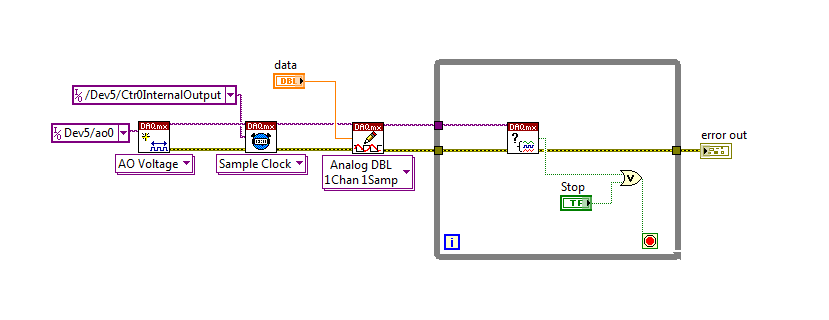
I spent some time thinking about it and I realized that you can technically use a fundamental mission of the analog output, as you previously wrote that runs continuously. However, the generated output samples are controlled by the sample clock pulses, and can be manipulated to fit our needs "suspension."
To do this, we will need another counter task that generates a pulse train (see our examples of shipping under material input and output > DAQmx > generating digital pulses > generate dig Pulse Train - Continuous.vi) that stops and starts the user to choose. This can be in another quite VI or controlled by software. We will use this as the task of our output sample clock.
Then, the task of the AO, wire a constant to the sample clock source and select ' DevX/CtrXInternalOutput"based on the counter that you specified in the task of counter. You will need to choose "I/o name of filtration" and check the box that says "include advanced terminals' and right-click of the constant. See picture attached as a reference. In this way, the task of the AO is constantly running, but it generates only actually all data when the meter running task.
Let me know if you have any questions!
Have a great day!
-
poor performance analog output (error 200018)
Hello. I have a 6124 SMU Board with controller real time SMU-8102. the Council is speced to MECH 4 analog outputs. / s (one lane), but I have problems to operate at anything beyond about 500 kech. / s. I enclose my example below program. If I put the rate at 500 k, it works. If I put 1 m, it does not work and I get the error 200018 (DAC conversion attempted before Conversion data were available). I use the DMA transfer.
I also tried to increase or decrease the number of samples written by loop (between 50 and 300) and using a loop timed in labview real-time. That essentially gives the same result (sometimes I get error 200016 instead, "exceeding accuracy onboard device memory").
Because the controller is a dual core controller that do literally anything else (what I showed is the whole program, nothing else running), I don't know that I have some setting wrong software. I can't believe that this controller is unable to deal with this card. Does anyone have any suggestions on what I might try?
Version of LabVIEW is 2010 and DAQmx version is fairly recent.
Ok. I thought about it. Here's an interesting fact. At the rate of 1 MECH. / s, tries to write to 4096 samples each microseconds 4096 works perfectly well. But any attempt to write to 4095 samples fails! 4095 course is 2 ^ 12-1. It seems that DMA was running only transfers of 4 k at a time, so when he got 4095 samples, he was waiting for a sample more start the transfer, but at the time where he got this sample, it was too late. I changed DataXferReqCond property for "almost complete." Now, I can write about 150 samples at a time instead of 4096. Greatly improved!
Moreover, it would be really good to put in the text of the error message for the error 200018 so that others live several days tearing their hair like I did...
Thanks for the help
Daniel
-
Redeclenchables/continuous to a custom waveform analog output?
Hello
I try regular output an analog signal using the box USB-6211 and Labview2009. I looked at various examples of waveform, including the retriggerableAO.vi example, but I can't seem to understand how to send a 'waveform' custom stamp (terminology is perhaps the question). In all the examples (including waveformbuffer), I ran across the single waveform, the options are sine, square, etc. Previously, I posted on this forum looking for hardware suggestions (link here) and explained what I try to do and got the big help. To sum up, I would like to read a 'waveform' from a text file, send it to the usb-6211 buffer and then continue to an analog channel. At the same time, I'll use the beginning of the analog task to trigger a digital signal once per cycle as well.
I got in what concerns the establishment of the waveform, but am stuck to figure out how to get into the buffer and setting the frequency, etc.
Thank you
Gabe
Hi Gabe,
Dennis is correct that it will take some room to modify the existing screws to fit your need. As he says, the Con Gen tension Wfm - Int Regeneration.vi Clk - no example provided with LabVIEW. In the example, it can be shown that there is a custom VI used to explain the problems that arise when a waveform of a given frequency to a frequency of sampling and outputs analog specified.
With all that said, it seems you want to read from an existing waveform file that you created and this waveform to an AO output channel. There are a few things that will be needed to know before proceeding:
-What is the waveform as you try to output (5000 samples, 10 k, 100 k, etc.)?
-What pieces of the size of the wave you want output (100 samples at a time, etc.)?
-you want to again and again, or simply run through once the waveform looping?
Assuming that you already have the waveform and will only step by step, here's what I would like:
-break the large waveform into smaller pieces of waveform of standard size
-import the waveforms in LabVIEW and create an array of waveforms
-bring the waveform in the example Dennis mentioned previously with automatic indexing enabled on the tunnel
-Remove the generator of wave functions existing the while loop
-wire your indexed table of waveform for the data of the VI DAQmx of analog output terminal
It is possible that you will have to play with the settings of your waveform and timing of your VI, but this should be a good starting point. Please let me know if something is not clear or if I have misunderstood your original message. Have a beautiful reast of the day.
Best,
-
Read analog output channel value internally
According to this you can read the values of analog output of return without having to physically connect the wires.
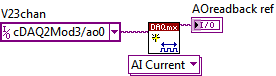
By using the technique described in the example given (DAQmx_Read_Output_Internal_Channels.vi) I'm reading a current area of OCCUPANCY on my compactDAQ cDAQ-9174 with a module of analog output current OR-9265.
The output channel is created in MAX and my vi can write values to him without problems
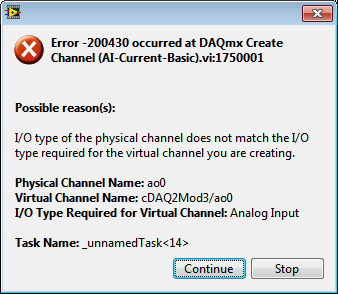
But when I try to create an analog input channel to read the output, an error occurs.
What I am doing wrong?
This is not supported by my hardware?
Or is the example given in the above incorrect link?
The example is 10 years old. Maybe, it does not work in LV2013.
Hi Jocker,
The link was not attached to your message, but I guess that's it: http://digital.ni.com/public.nsf/allkb/CB86B3B174763C3E86256FFD007A2511 as there the example of vi you mention.
The error you are getting is due to the use of the channel for analog output and trying to configure the task as a task of entry. You must use _aoX_vs_aognd as the channel of the task rather than on the output channel. This compares to the ground for the analog output values.
The NI 9265 is not on the list of the C Series modules that have internal channels:
So I guess that the module is not able to compare its output to ground. He would appear in the dropdown of the channel names if available.
Pete
Applications Engineer OR
-
DAC (analog output through sreapder?) on Spartan 3 FPGA
Hello world
I searched on LabView training exercises for the 3rd Spartan Board, specifically the DAC.vi and the DAChost.vi in the exercise 8. The screws are in the solution folder, but there no real explanation for the DAC specifically in Scripture in the exercises section. I was also watching Xilinx in the Board Manual, but I can't seem to find the answer to my question.
My goal is to be out put an analog signal that is adjustable between 0 and 3.3V as a control to another system while the rest of my code is running. Of course, the premade DAC vi can be used to put analog voltages on the DAC pins, but I wonder is - it possible to the analog output of the signal through one of the connectors spreader (while the other digital connectors are also output)? It seems like it should be, but I don't know how to implement. If this is not possible, then well, I guess I have a big problem

Thank you
The only place where the DAC would release would be the pin of the DAC. I doubt that there is other options routing so that the PIN because you can't get an analog signal by an FPGA.
Kind regards
Matt M.
Maybe you are looking for
-
How do I reinstall yosemite after installation of el capitan
El Capitan is originally vmware to freeze
-
Windows 7 - error Code: 80070570 (cannot install KB979688, KB2296011 & KB2378111)
cannot update win 7 x 64 based security systems(1) KB979688 KB2296011 2) KB2378111 3)
-
Ink cartridge # 99 does not fit into the printer, only #97 will fit
Hello, I tried to install the print cartridge # 99 and he doesn't, oddly enough the # 97 cartridge fits very well. It seems the line (party at the top of the cartridge Bay won't let me install the cartridge, as the #97 the manual for my HP 6540 has
-
Dell XPS 8700 ceased to detect any Wi - Fi
I recently purchased an 8700 XPS (Windows 10). He acknowledged my wifi router immediately during installation and was able to access the internet very well for about a week. In the last day or two, I noticed he started having intermittent loss of con
-
Inspiron 7559 unusable, no BONE can install/run on it
Hello. I bought a new Inspiron 7559 [7559-1264] I ran its own OEM Win 10 single home language well, but I'm a programmer, and which is not enough for me. I have a Linux system next to a win 10 full Pro of the system. I tried to install/run Arch, Ubun