PWM output
Hello
I would like to know if someone could make a recommendation for me. I'm looking to use a material OR PWM output to control 2 motors. I used only for usb 6008 front and concluded that I need a different material for this, but think also that he does not need to be Compact RIO. I need something that does just what I need it to do. Just output PWM for control of 2 motors. The material to drive the motors is not a concern at this time, I'll build later. I just want to see what are the solutions the cheaper for something like this (although I know that this is not "cheap").
Any recommendations would be greatly appreciated.
Thank you
Hey nano,.
If there is feedback involved, your terms of latency will be an important factor in the choice of a hardware configuration. In the order of latency:
USB DATA ACQUISITION< pci="" daq="" (windows="" )="">< pci="" daq="" (rt)=""><>
For the acquisition of data-driven solutions, I suggest to look in the series ( PCIe-6320, USB 6341) X. These have 4 counters that support a wide range of including functionaity to generate PWM signals. If you don't require comments, these commissions have the power output meter in the buffer. If you need your comments, I recommend you to consider alternative Council PCIe latency is much lower than that of USB. RT and FPGA solutions give a latency low but can be quite expensive.
Best regards
Tags: NI Hardware
Similar Questions
-
Problem setting up an encoder input and PWM output tasks on CompactDAQ
I use a chassis with a modules 9474 cDAQ-9174 and 9411. I do not think it is important, but they are the cRIO-XXXX modules NOR old provided with a test configuration that has been distributed to early adopters. I use DAQmx tasks in an application (C libraries) to read (angular position) quadrature encoder and drive a motor directly with PWM current (pulse output). For various other needs, my tasks Setup is as follows:
[DAQmx] MajorVersion = 9
MinorVersion = 2
[DAQmxChannel venture 9411 wheel entry/AngularPosition]
CI. AngEncoder.PulsesPerRev = 500
CI. AngEncoder.InitialAngle = 0
CI. Encoder.ZIndexVal = 0
CI. Encoder.ZIndexPhase = a Low high B
CI. Encoder.ZIndexEnable = 0
ChanType = input meter
CI. MeasType = Position: angular encoder
CI. AngEncoder.Units = ticks
PhysicalChanName = cDAQ1Mod2/ctr2
CI. Encoder.DecodingType = X 4
[DAQmxChannel venture 9474 PWM output/PulseOutput]
CO. LTD.. Pulse.IdleState = low
ChanType = output meter
CO. LTD.. OutputType = Pulse:
CO. LTD.. Pulse.HighTime = 5.0000000000000004E - 006
CO. LTD.. Pulse.LowTime = 5.0000000000000002E - 005
CO. LTD.. Pulse.Time.InitialDelay = 0
CO. LTD.. Pulse.Time.Units = seconds
PhysicalChanName = cDAQ1Mod1/ctr3
[DAQmxTask venture 9411 wheel entry]
Channels = venture 9411 wheel input/AngularPosition
SampQuant.SampMode = continuous samples
SampClk.ActiveEdge = Rising
SampQuant.SampPerChan = 100000
SampClk.Rate = 100000
SampTimingType = sample clock
SampClk.src=/cDAQ1/100kHzTimebase
[DAQmxTask venture 9474 PWM output]
Channels = venture 9474, output PWM/PulseOutput
SampQuant.SampMode = continuous samples
SampQuant.SampPerChan = 100000
SampTimingType = implied
RegenMode = allow regeneration
[DAQmxCDAQChassis cDAQ1
] ProductType = cDAQ-9174
DevSerialNum = 0x18B3EC0
[DAQmxCDAQModule cDAQ1Mod1]
ProductType = NOR 9474
DevSerialNum = 0xDEDF40
CompactDAQ.ChassisDevName = cDAQ1
CompactDAQ.SlotNum = 1
[DAQmxCDAQModule cDAQ1Mod2]
ProductType = NOR 9411
DevSerialNum = 0xDEDB24
CompactDAQ.ChassisDevName = cDAQ1
CompactDAQ.SlotNum = 2
Each task works fine on its own (i.e. without the other). The problem is that if I start the task of the encoder first and then the task PWM, the latter causes an error:
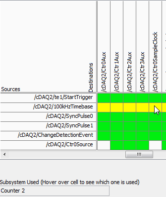
Error-89137 occurred to the DAQ Assistant
Possible reasons:
Specified route can not be satisfied, because it requires resources that are currently in use by another route.Source device: cDAQ1
Point source:
80MHzTimebase
Destination device: cDAQ1
Destination
Terminal: Ctr3SourceNeed for resources in use by Source
Feature: cDAQ1
Terminal of source: 100kHzTimebase
Destination
Feature: cDAQ1
Destination terminal: Ctr2SampleClockThe task name: _unnamedTask<61>
I don't know why this is, but if I start the PWM task first, and then the task of the encoder, it also works. I should also mention that initially I was using counter 0 encoder, which caused a shift in the 100kHzTimebase to Ctr0SampleClock, which, according to the ways of device 9411, is not supported. Yet it worked (in itself). I wonder if this is happening under the hood isn't quite what is shown.
What is exactly the conflict and what can do to avoid it? The reasons for having to use specific modes and the settings (for example, the 'continuous samples' with 100kHzTimebase clock) are rooted in various performance and requirements of optimization that were created in a previous version of our software, so I prefer not to take a completely different path, if some small changes would lead us to correct the problem.
I appreciate your help.
Kamen
Hi Kamen,
The time base of 100 kHz is not a direct route to the counter sample clocks, the device actually uses one of the other counters to complete the road (the routing table is a little misleading here because it shows 2 meter that one always doing road - in fact it will be any available counter):
So in your case, when you start the task of the encoder, it uses one of the other available counters to complete the configured road (100 kHz to ctr2 sample clock timebase). Of course, she chose meter 3.
Possible workarounds (looks like you have already found one yourself):
1 start the PWM before the task of the encoder task - if the task PWM starts first the counter is already booked and the task of the encoder would choose another available counter to complete its road.
2. explicitly reserve the PWM task before you begin the task of the encoder (if you need to start the task of the encoder first).
3. use cDAQ1/_freqout to generate the clock sample 100 kHz signal and use this instead of routing to the time base of 100 kHz to the counter sample clock.
Change autour counters should also work, but I'm not 100% sure how the unit selects which counter to use for routing (I don't expect change in the future, but if it's not explicitly spec'ed somewhere so I wouldn't take my chances)-if it were me, I would choose one of the other options above.
Best regards
-
cRIO - H bridge using the PWM output and input only encoder control
Hello
I am currently working on a project to control a 230V brushed servo motor using cRIO. The engine drives a linear step and the final project needs to create a control of position of the engine that the user is able to enter a speed, position and control steps to move to this position.
I use a bridge using NOR-9401 and H to power the motor circuit and a PWM output to move the engine. I also have an encoder, quadrature, connected to a NOR-9403 read position and speed. I use the example program of encoder for the NI 9505 - in my application.
There is no voltage or current on the drive circuit sensors so I wouldn't be able to have a closed loop current in this case. The scene release mechanism is such that the position is locked if the motor does not move and I do not need a torque control to keep the engine in place.
To achieve this, I just wouldn't be able to use a single PID VI (probably the FPGA VI express for discrete PID)?
I am not very well versed in the theory of control, and therefore no indication in the common sense would help me a lot.
Thank you very much!

Sexy,.
in general, it is best to use a cascade control loop structure but in principle must also be able to use the output of the control loop of position as an input to the PWM generator. The main disadvantage of this configuration is the current limitation missing. Without current meaning is no longer the only way to protect your engine from drawing too much current to limit to the current maximum output of your diet, or to limit the maximum duty cycle of PWM. Without current information, the last method is quite inaccurate, but better than nothing.
I agree with Mike, you should look in the examples of the 9505 module and use the controller position vi of these examples. This PID controller is optimized for motion control applications and it is implemented in the fixed point arithmetic, offering the best performance on and FPGA.
Kind regards
Jochen Klier
National Instruments
-
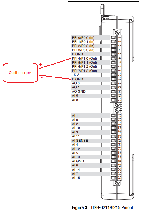
PWM - output meter (PFI4) USB-6211
I managed to control a motor based on PWM signal output via USB-6211 AO continuous. Now, I'm trying to use the Terminal counter instead.
Can't seem to make it work. NA not get a signal when link the PFI4 terminal to an oscilloscope.
I don't know wheather my coding is wrong or does not have my wiring (i.e. of USB-6211 for motor continuous). I need to use the terminal of meter that I used the analog output to a different measure.
Please advice. Attached encodings.
Thank you very much.
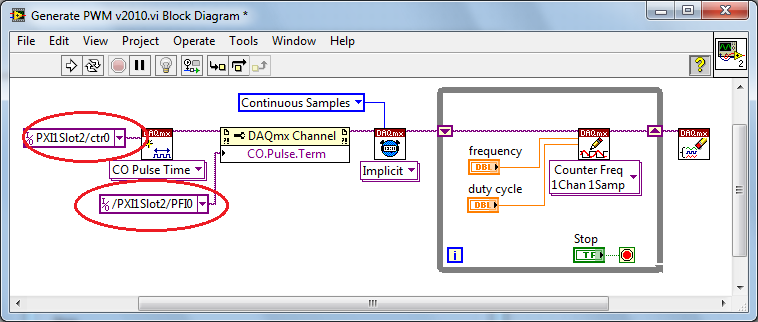
Front of conneting to DC motor, make sure first that the PWM is get generated correctly... use oscilloscope.
And have you changed the constant (physical terminals) for your device...?
Change to:
Dev1/ctr0 & Dev1/PFI4 and the scheme of connection must be:
-
Hello
currently I'm controlling an electric motor through its controller. This Controller has max signal 24V PWM as a speed controller. Unfortunately I PXI with the NI 6528 card, which has no counter outputs. I need 100 Hz. STI is possible to use this card to order this engine? If it is possible, how can I program it? I also have a card NI 6230, which has exits of meter, so there is only 5V output meter, I prefer to use 6528 card instead of going to electronics to build a circuit to 6230.
Thank you in advance for your help!
Martin
Hello
The example you are using has a while loop inside of it. So the VI does you will remain in the first loop ((deuxieme page of the Structure of sequence) as long as the Subvi is running (= until you stop it or there is an error). I propose to spend time on learning the basics of LabVIEW structures to better understand it. Here's a tutorial example, which may help you understand, how work loops: http://zone.ni.com/devzone/cda/tut/p/id/7588. This tutorial can also be useful: http://decibel.ni.com/content/docs/DOC-1694. There are also other tutorials - just search on ni.com.
-
I have a NOR-9477 module on a cDAQ chassis. I was wondering if I can use this module to generate a PWM signal to the relay. It seems from reading the cDAQ 9172 User Guide which only "correlation" modules DIO are able to do this. The NI9477 module does not say if it is a module "correlated" or not, but it seems that it is a 'static' module which is used for signals to slow evolution. But given that the maximum rate in the specifications is 8 microsecs, can I exit a 20 kHz PWM signal which is software programmed to control my pump? Thank you!
Please ignore this thread because a similar thread already exists.
-
LabView PID control with PWM output and ramp / soak.
-
How can I measure the output of a sensor pwm ultrasound using the module or 9403
How can I measure the output of a sensor pwm ultrasound using the module or 9403
Khalil,
When you say 'measure' the PWM signal, exactly what to tell you?
You're looking to measure the frequency or cycle of the signal function? You count the edges of the PWM output increase? Looking to control the waveform?
With reconfigurable FPGA hardware, it is up to the user to define the function of the physical i/o on the FPGA chip. By connecting the signals as Adam suggests your digital pulse will be brought to the cRIO. In your FPGA program, you define the function. You can set a base counter or transfer digital data from single point to welcome you cRIO for floating-point more complex treatment. Example FPGA programs are located in the http://www.ni.com/IPnet.
Hope this helps, please post any additional questions.
-
Voltage offset problems with the NO-9401 for PWM signal output
I try to create a 20 kHz PWM signal to drive a motor control circuit uses the NI 9401 module in the chassis OR cRIO-9073. Generating the PWM signal works. For some reason, changes in shift of power as the market factor is increased. It is less effective for the engine, as you can imagine.
The code I am using is the finder of the example, for the generation of PWM on an FPGA and is attached.
I thought that it worked before but may have used the the NOR-9505 rather PWM output to test my circuit. It would be unreasonable for me to do this as a permanent solution.
The problem can be summed up as: with an increase in the liability of the cycle the voltage line (offset) movement of the output signal in the negative (according to ADGE) Basic or down. The Vpp signal is correct and does not change. Against ticks from 0 to the maximum of 2000 ticks (duty cycle IN), the offset voltage shift is such that 100% the level of full voltage is 0V.
Any ideas as to why this offset voltage shift that happens?
Do not be dismayed, I worked on the problem. There was a connection problem - I thought I was logged in as reference Earth, but it has not been properly clipped.
-
Hi all
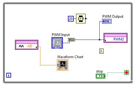
I'm trying to generate PWM with Laminary LM3S8962 signals.
At first, I thought that always the entrance of the PWM output is the ratio between the width of the pulses.
I connected to AI0 PWM2 and run this VI:
By changing the value "PWM Input" AI0 strangely varies
Hi Neil84,
Thanks for posting on the Forum of National Instruments.
Just to add some information about PWM with LabVIEW Embedded for ARM. Set you the divider in the properties of elementary school of e/s of the project? Here is some information pulled using LabVIEW:
«The PWM frequency is the inverse of the period PWM.» A 16-bit system clock divider controls the frequency. For example, if the system clock is 50 MHz, the lowest possible PWM frequency is about 760 Hz. If you need a lower frequency, predivide based on the system clock of time PWM. To change the predivider, click the basic I/o node in the Project Explorer window, and then select Properties. This property affects the dating: 0/1, 2/3, 4/5. For example, if you set the output frequency 4, you also set the output frequency 5 because the two outputs share a common time base. "
Thus, with a 50 MHz clock and a 16 - bit divider, you would get 50 MHz/2 ^ 16 = 762, and therefore the lowest frequency you can achieve (using the value of the divisor of 64) would be around 12 Hz. You set this value of divisor of the project for the e/s specific PWM.
Let me know if this clears up things or if you have additional questions.
Kind regards
-
Entry of absolute encoder PWM w / 6008
Hi, I'm quite new to the DAQ world so please be easy on me.
Well basically, I have acquired a free 6008 and want to use it to track the absolute deviation of angle of a device I have.
My scope involves the use of a labtab (USB only), as well as a range of measurement 0-90 degrees with an accuracy of 1 degree at most.
So I came to the conclusion that I have to get an absolute encoder.
Watching the encoders and their respective exits, I found the following: SSI, Linear Voltage (0-5 Volts) and PWM
I have falling SSI my list because it seems a PCI data acquisition card is a requirement, and the linear voltage is all simply not precise enough, because the encoder outputs (0.056 volt/deg) and the 6008 can be read only with accuracy intervals (0,138 volt). Which means (2.484 degree/interval), I think.
in any case, the last style of output that I found was the PWM signal.
The encoder http://usdigital.com/products/encoders/absolute/rotary/shaft/ma3/
If I have good outings (at intervals micro-sec 1026), where the duration of the pulse is the position of the encoder. (1026 counties/revolution).
So I guess I have to be able to read the pulse of the order (1 micro-sec) for (1 head).
My question is whether or not the 6008 is able to acquire the data for my use in LabView.
Counter the 6008 says its able to detect more than (0,1 micro-sec) pulses.
Does this mean the 6008 so capable of doing the job?
Any help is grateful, as I have very little experience with LabView or DAQ instruments.
Thank you.
It is a limitation just to the meter of a USB-6008. What you describe with 2 counters is actually very close to what we do for measures high frequency on our complete recommended counters. The pulse actually measure that requires only one meter on our E-series, M-Series devices, meter Timer and X-series.
In regards to the analogue output of the absolute encoder, I think you should be ok with the resolution. The output of the encoder is 0 to 5V. The typical accuracy on the 6008 for this interval is 4.28mV for differential connections. Step for each degree size is 5 /(2^10) = 4.88mV. Thus, it seems that you will be able to get a precision less than 1 degree.
If you need better accuracy or would prefer to make the PWM output type, I would look at our M-Series USB for a portable data acquisition solution. Let me know if you would and I'll give you a few recommendations.
Regads,
Paul C.
-
REQ: Example of Pulse Train dig where PWM varies.
Hello!
I'll put up a temperature controller. I want to use the output of the counter of my DAQmx device to create a PWM signal that drives the relay to my ban on heating. A regulator PID VI will be used to set the PWM (0-100%) of the output of the counter. I tried several times now, and my resulting code has always been buggy to say the least. I ran into issues:
1 PWM output meter does not output of 0 or 100%. As a matter of security, 0.0000001% or anything that is simply not enough close to 0.
2 "Errors of task is not complete" when you try to change the value for the "DAQmx Write - Freq Counter 1Chan 1Samp" PWM.
I lived the examples provided by OR for the setting of PWM in LabVIEW, but I can't find a good example of what I am trying to accomplish.
Attached, this is probably my best attempt (error). The DAQmx switch s VI within the conditional blocks are my attempt to get a score of 0%. I get the error #2 in my list a lot with this code. Also, the observed output does not always seem to be correct...
I'm tempted to use a quad-packed op amp to make a PWM circuit which is driven by the analog output. Unfortunately, it seems much simpler to work on my mistakes of diving analog program. My approach is perhaps far off. Any help would be greatly appreciated.
Thank you for your comments.
-Nic
I think it's because as the analog inputs on most hardware DAQ is multiplexed, meaning there is only a CDA shared by all channels, so we can't have two ongoing independent measures. Similarly, if a complicated task requires counters (and there are often only two of them) then you are limited to what can be done at the same time. But MAKING simple tasks should be very independent of the other, since they still shared resources. In a way, DAQmx makes things too simple, because it is not always obvious what each task is hogging material resources.
No offense to the thing 'prohibition of heating. When you used the expression of the second time I was wondering if it was a special type of equipment that I wasn't familiar with.
-James
-
Problem when the PWM signal combinning and analog signal TOGETHER!
Hello everyone,
first I DAQmx 6212, and I need to run the water pump small (9V - 16V) that should be driven by a PWM signal; I also have a motor (5V - 13V) for a water supply which must be controlled by an analog signal and it has built in a force feedback potentiometer, I logged onto this potentiometer correction + 5V the DAQmx and used the output voltage of the third extremety as a value to diagnose to know the position of the engine.
My VI shows:
1 is a normal meter production to create my PWMout signal.
2 is an analog input, I use it as a PWMin to the LabVIEW to diagnose what is happenning in my pump water through the cycle and frequency.
3 is an entry of the third extremety of the analog potentiometer.
4 is an analog output that I used as power supply of the motor valve and I used an AC/DC amplifier for aplify signal the DAQmx and the motor road, between the two (3. 4.) I made a comeback with a few calculations, I had a P-controller to know the real position of the engine valve.
My problem:
When setting to 1. and 2. in the same VI only, I get an own PWM output with no problem.
also with 3. and 4. in the same VI only i can control the motor valve without any problem.
but when I put all these 4 set found in the attached VI, I have a problem as the engine valve turn continuously without stopping even if I change the position of the valve between 0 and 100%, I should mention that I see a PWM normal outside a signal on my oscilloscope, another thing to delete one of (1 or 2) and run the engine valve VI works fine without any problems.
so this my problem, if you can think of any solution please let me know.
Thanks in advance for your help.
Kind regards
Caliente
Here's your VI, slightly modified so the two analog inputs belong to the same task. This if only for purposes of illustration, I him have not tested. You will still need to do some debugging.
While changing your VI, I noticed another potential problem with your original configuration. You have configured the two tasks of AI for the same frequency, but read you 10000 samples of one of them and only 100 samples from the other (and throw it most of it). Data acquisition data are buffered, and if you read as fast as you acquire, the buffer fills eventually. If you read 10,000 samples of a channel, and the other channel acquires at the same rate, then when you read from the second channel you will get old stale data or an error full buffer.
-
Hello world.
I wrote a program of temperature control in labview and used the PID Toolkit for it.
The entrance to the PID is the measured temperature and the output is a PWM signal fed to a relay that turns heater on or off.
The control works but I want the temperature to be stable within a range of + - 2%.
Currently, the temperature varies more than that.
IAM sure, this is the setting of the PID.
Because I have not worked with regulators PID Iam not exactly how to tune my system.
The best way I found is to zero I and D and make the system oscillate with P.
The only problem is that the system of temperature is so slow that it takes quite a long time to reach the set point which in turn would mean a lot of hours of tests only.
Now Iam just wondering if there is a faster way to set the PID controller?
Thanks in advance,
Best regards
Michael
I've used this method several times with slow heating appliances. It can take a long time to reach a stable temperature, but at least do not monitor constantly as he approaches this value.
In figure 3.4, Yes, the Min value is the initial value that is stable. It is OK to start an initial PWM output of 0, which speeds up the process, if your radiator is already at a steady temperature (the temperature in the room).
In general, the difference between the output of the first and the last values, better will be your control (you will get best results of going from 0 to more than 50% to 5%), but it will take more time to settle to a new value and of course you must ensure that you do not exceed the capabilities of your system. It's a good idea to have a separate alarm system in place that can cut power to heater if you exceed a temperature, especially if you plan to walk away from it until it stabilizes.
To a fixed cycle, the system will not continue to heat up indefinitely unless you have a perfect insulation without heat loss - but, as I mentioned above, do not choose a value that will not cause the system to overheat.
-
LabVIEW ARM embedded systems tutorial
Nice day
I started working on a project using the Development Council LM3S8962 to initially work lencuaje C, is very economical and in some cases, better than the Arduino

but I see that you can also work with Labview, if anyone has worked on this and can give me some feedback would be very happy
Hi Tom,
If you have questions about the material/pine itself, I would consult for this piece of hardware user's guide. For example, here: http://chess.eecs.berkeley.edu/eecs149/sp09/docs/EK-LM3S8962_EvalBoard_UM.pdf
The software/hardware connection is usually quite simple. For example, if you create a point basic IO and select PWM0, then everything that you send to this node will go to the PIN marked on your map as PWM0. In addition, there are a number of properties in the software that you can configure in the software for the PWM output: http://zone.ni.com/reference/en-XX/help/372459E-01/lvarmhelp/arm_eio_prop_pwm/
If you have specific questions or specific things that do not work, I am able to help you, but I think it's all general support material we have.
Maybe you are looking for
-
How can delete old messages that have lost the current interest for?
I am interested in the purge my last questions, who have now lost relevance mainly because they were related to previous versions of FF. Is it possible now? If it is currently unavailable, then I would leave it as a suggestion for future versions of
-
What price has been the Logic Pro 7.2 update? (American or British price will be...) When he came out to the origin? Thank you...
-
How to extend the display of two monitors
Original title: disorders bi-ecrans I tried to set up a second monitor to my computer. I don't have that one port, so used a double adapter cable to connect the second monitor. The computer will be in the image of the first monitor on the second, but
-
I accidentally deleted my clock on my list. How can I get that back?
I ACCIDENTALLY DELETED THE CLOCK GADGET ON MY LAPTOP. HOW HE REINTALLED?
-
What is the fix for Windows XP Mode do not install on a system with a bulldozer to AMD CPU?
I'm on OS Windows Ultimate 64 bit on a desktop computer to measure with an AMD FX 6100 processor. I understand that Windows XP mode can not be installed on a computer with this type of processor, but I think that there is a fix for this. Anyone kno