PWM with NI 9264
Is it possible to generate a PWM signal to a certain duty cycle with the NI 9264 16-channel analog output module?
Thank you
Robert
Tags: NI Hardware
Similar Questions
-
Hello everyone,
already, I asked once about the creation of PWM with hardware. And I was pleased with the response. But now I found 94xx Series-USB OR hardware. Here are the materials of high-voltage-Digital i/o. If any of you have already met with this one, would like to hear your conclusion about them. Would also appreciate if you could answer my question:
Is it possible to create a PWM Signal with NOR-USB 94xx?Thank you
Grigory
Grekov wrote:
I'd be more interested in the USB Module NI 9472 USB connection. Because it's the only one that would match my request.
What is your application?
Why don't choose you something in this list.
If your condition is out to say 24 v PWM signal... you can also plan to use a custom circuit intermediate, not only to scale the output signal of the device (at 24 v) but also the reader following circuit.
-
4 PWM with 9472 9174 chassis module possible?
Hello
is it possible to generate 4 independent PWM with a module on a 9174 chassis 9472? In the past I have already achieved 1 with a PWM module 9474 (same chassis) with the help of an independent timer 9174, so 4 = 4 PWM timer?
Concerning
cpschnuffel
Hello
There may be situations where you need to use the blocking process counters / synchronizing, but basically you have 4 PWM channels with 4 counters.
Marco Brauner NIG.
-
phase shifted PWM with Ni 9401 and Crio
Hello
Do you have an idea of pwm shifted 180 degrees?
(duty cycle frequency and variable difficulty)
I tried a design, but it seems in the graphics design works on the realtime.vi but it does not work with the fpga.
Graphic output pwm FPGA are distinguished by the real time as you can see in the pictures.
On the other hand, VI Fpga produce two pwm, as seen in the oscilloscope when the fpga VI runs.
However, there is no phase shift between the PWM waves.
It is a part of my thesis, but I'm stuck in this problem, so I need assistance on your part.Thank you.
Best regards;
My hardware:
cRIO-9024 and cRIO-9118 chassis
NOR-9223, 9263 - nor, nor-9401, or-9474
two nor-9225 and nor-9227
Hi Maurice
Thank you for your help.
Yes I want to that they will be moved with the right variable and 10 kHz. I put 49% maximum duty.
I put the output into the same output block.
Square wave generator does not accept 'loop' while.
I have attached a simple FPGA project file. Could you please tell me what is my fault?
The resulting Pwm frequency is 10 kHz, the only problem is always the shifters.
So, I always need assistance.
-
create the pwm with mcc usb signal 2408
Hi all
I want to generate a square wave of PWM adjustable frequency and factor market out of my usb usb MCC 2408-2ao module.
I know thatI could use while loop with a sequence of plate inside to put on and off of a digital output on an ongoing basis and by changing the duration the sequence of flat images and the time between one and another iteration of the while loop I can vary heavy duty and often... but it seems a little tedious to do.
Is there an automatic way to generate a PWM signal to measure and send it to the output of the USB module in Labview?
Thanks for all your help!
-
generate the signal f = 50 Hz with NOR-9264
Hello. I am Sorin.
I need to generate a sinusoidal waveform with f = 50 Hz, U is 3Vrms. I have a C, OR-9264 module. Is it good? Or can it only generates SCR?
I don't have C modules: I for RTD, V, mA, universal and AO for V and mA.
What can I use?
Thank you.
It DOES not say that it displays up to 25 kech. / s (25000 samples per second). It's more than enough for 50 hz.
-
Help build control PWM with Accelerator and arduino
Hello
Good night
I'm new to labview
pls help me to build a project, or give the design, because im confused how connect accelertor to PMW with arduino.This regulation:
Create a program using LabView configuration between sensor
Accelerometer in the current motor speed continuous is used. Where motor speed
DC will change according to the level of the accelerometer tilt sensor.IM waiting for your happy,
Please share .vi
Thank & regards,.
Kidz stew
Hello
TRY this and enjoy ;-)
-
myRIO digital servo drive with PWM
After scouring the internet for answers, I realized that I have neglected this resource.
I'm testing some small digital servos that will be used in a senior design project. When we received the myRIO I created a simple VI to drive a servo using PWM with a frequency of 50 Hz and by varying the duty cycle between 5 to 10%. I used a good servo is provided with an arduino kit, and it worked perfectly. However, the Blue Bird BMS-385DMAX servos arrived and when I tried with the VI I did, it didn't work. I confirmed that the servo works by running with an arduino, it just does not work with the myRIO. I'm not an expert of labview, and I'm new to the platform of RIO; any advice would be greatly appreciated.
I joined the project. Ignore the KeyDutyCycle VI and the variable shared; It was something I experienced, but has not used.
You use the myRIO + 5v and Gnd of to power the Servo?
MyRIO + 5v is limited to 100 my output which may not be sufficient to power the larger servo. Try feeding the enslavement of another source, but still using the PWM myRIO. MyRIO PWM (and all other outputs digial) should be ~3.33v as 'high '.
-Sam K
Join us / follow theGroup of pirates of LabVIEW on google +
-
Generate PWM signals with 1.5 ms pulse width
Hi all
I'm working on a project where I need to generate a PWM with a pulse between 1.3 and 1.7 width ms to order a servo rotation continues. LabView is in communication with an arduino Uno microcontroller by LINX. My original plan was to use the milliseconds of wait function in LabVIew to do this. I put the PIN PWM high, wait 1.3 or 1.4 ms then set the low axis for 20 less ms pulsewidth. before repeating. This is how I have gnereate one using the Arduino IDE pulse width, so I thought I'd be able to do something similar here. However, as I'm sure is already obvious to anyone who reads this, the milliseconds waiting finction in LabView only accepts the whole entries. Arduino IDE is similar, but there is a delayMicrosecond function that can be used, so if I want 1.4 ms I use 1400 US snf then convert it in ms for the 20 least part. How can I do something similar in LabView? Also. When I run the program as what with a 1 ms pulsewidth I have a strange behavior. It in fact generates a PWM signal, somewhere between 0.75 and 1.25 ms and with a period between 50 and 54 ms, it turns into a model each about half a second. I'm using LabView 2014. Any ideas?
Chris
You can't get that kind of resolution with Windows and any delay you specify will have considerable jitter due to Windows. If you can pass values with Linx and allows the arduino to control them, stick with that.
-
How to use NI 9264 and NI 9205 with NI PXI-7813R and cRIO-9151
Hello world
I am currently working on an application in time real NI PXI-7813R (map FPGA) and NI PXI-8184 (on-board controller). They are all in an NI PXI-1031 chassis.
I need to generate/receive analog signals.
I already managed to use the SCB-68 with my NI PXI-7813R (FPGA card) to process digital signals. (Slot 0)
Connector 1 and 3 of my FPGA I have respectively cRIO-9151 with NI 9264 for analog and cRIO-9151 output with NI 9205 for the analog input.
- with NI 9264, I have on every 16 outputs-10, 5V (!) Isn't it supposed to be between-10 and 10V?), whether or not the vi runs. (But not when my PXI turned...)
- with the NI 9205 module, I always get-32767 when the VI is running, regardless of pressure I apply. (I tested AI0 and AL10)
Maybe is my hardware not configured properly? I did the configuration automatically, when I started the project, Labview detected the devices connected.
Unfortunately, MAX does not seem to be useful because inputs and outputs are on the FPGA...
Any idea?
Thank you
PS: VI on the FPGA is really basic, only read/write controls.
Hello
Back with the solution...
My modules came! Each of them has been plugged in the wrong cRIO-9151.
This must occur after the first configuration.
I noticed when I right click on my fpga device > RIO Device Setup. I wanted to check the devices again, but crashed for Labview.
I could also have seen 'Connector [number]' (automatically added by Labview) and the removal of material number (9205 or 9264) in the project and check if it really was what I had.
Hope that my mistake will help someone in the future...
-
Hi guys!
I'm working on a project where I want to control a motor dc with VirtualBench and LabView.
I have the engine connected to a H-Bridge motor, so I need to send 3 digital signals from the DIO VirtualBench to H-bridge.
With respect to management, I figured out, but now I need help to get a PWM signal to one of the DIO pins.
I can generate a PWM of the FGEN but do not know how to export to a DIO PIN.
I can also generate a PWM with the Express-> entry-> function Generate signal in Labview. But I get an error when you try to write this signal to pin.
Or is there a way smarter or easier?
Help, please!
/ Christian
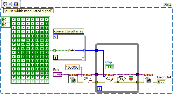
The digital i/o pins are supported as the SPI, I2C, static DIO (timed by the software) and exports of MSO Trigger or FGEN signals start. There isn't any feature PWM/meter.
It is not a way to generate a PWM signal real on the DIO pins, nor can you give a digital waveform to dig write. From the FGEN might be your best option here.
Another possibility might be to use (ab) the functionality of mastering of SPI. The following VI generates a modulated signal of pulse on dig/1 (MOSI) width. It will also generate signals on dig/0 (CLK) and dig/3 (CS), which may not be desirable, and you will have "gaps" between each call to read write of SPI.
-
Can I use a power supply from 14 to 15 volts DC with my computer
so I bought a p2-1013 desktop computer it has an apxd1-dm, the card mother itx micro with a continuous supply, integrated on the map.
in the description it says it needs a 19 v dc power, but I think that the jury needs 12v and 5v to operate so the provision would naturally be able to offer both voltages to 14-15 volts.
my questions are so
1. the Council use something higher to 12v or need something more?
2. is the continuous converter designed to not be able to correct the fluctuations of tension? (PWM with no correcton feedback)
3. does anyone think this will work?
probably a rather strange question, its for a school project.
any help would be greatly appreciated
Thank you
1. the Council use something higher to 12v or need something more?
No, the Council should not should eat something higher to 12volts. Common computer voltages are 12v, 5v, 3.3V and lower for the processor and the memory.
2. is the continuous converter designed to not be able to correct the fluctuations of tension? (PWM with no correcton feedback)
The computer is basically a laptop computer in a matter of funds. Any laptop I've owned uses a power supply AC/DC with an output of 18.5 to 19 volts DC @ about 3.5 amps. This configuration is tested... it is known to work. The section of DC-DC on board probably includes dividers voltage and voltage regulators for most of the functions with PWM for the CPU and memory circuits.
3. does anyone think this will work?
Honestly, I don't think you'll have a bit of luck you try to run the computer on 14-15 volts DC.
-
Hi all
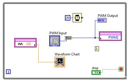
I'm trying to generate PWM with Laminary LM3S8962 signals.
At first, I thought that always the entrance of the PWM output is the ratio between the width of the pulses.
I connected to AI0 PWM2 and run this VI:
By changing the value "PWM Input" AI0 strangely varies
Hi Neil84,
Thanks for posting on the Forum of National Instruments.
Just to add some information about PWM with LabVIEW Embedded for ARM. Set you the divider in the properties of elementary school of e/s of the project? Here is some information pulled using LabVIEW:
«The PWM frequency is the inverse of the period PWM.» A 16-bit system clock divider controls the frequency. For example, if the system clock is 50 MHz, the lowest possible PWM frequency is about 760 Hz. If you need a lower frequency, predivide based on the system clock of time PWM. To change the predivider, click the basic I/o node in the Project Explorer window, and then select Properties. This property affects the dating: 0/1, 2/3, 4/5. For example, if you set the output frequency 4, you also set the output frequency 5 because the two outputs share a common time base. "
Thus, with a 50 MHz clock and a 16 - bit divider, you would get 50 MHz/2 ^ 16 = 762, and therefore the lowest frequency you can achieve (using the value of the divisor of 64) would be around 12 Hz. You set this value of divisor of the project for the e/s specific PWM.
Let me know if this clears up things or if you have additional questions.
Kind regards
-
Hello everyone,
I want to know if it is possible to make a signal PWM with LabVIEW control MOSFETs. My biggest problem is the equipment for this action. I'd appreciate it really answers useful. Thank you for your time!
Thank you
Grigory
P.S. the Datasheet of the MOSFETs are attached
Se see example attached here and you should be able to change the cycle frequency and duty as well...!
Edited: well, I must tell you, this code works well with any M, X material of the series using functions DAQmx.
-
Hello
I am writing a VI to control PWM with a microcontroller via a serial port. I wrote a simple code for the microcontroller that allows me to set the ratio of duty cycle on a scale of 0-65535. It works very well with Termite of Compuphase (RS-232 plug); The microcontroller invited me to an entry, expected that I would one, updates and expected another entry when I decided to send him. Now, I'm trying to get the same functionality on a LabVIEW vi but hit a snag.
When I tried to send my orders with a series read base and an example of writing, everything worked fine. I could see the prompt entry, write an entry and if I was quick enough, check out the update message. Even when I was not fast enough, I was able to check the update by monitoring the PWM pin with a Logic Analyzer. The problem with the basic example, however, is that I need to update the report to aura cyclical ratio, so I went for an example of reading continues writing. The problem I've met; is that I have to switch between reading and writing to make it work. When I do that, either I don't hold write it down long enough and nothing happens, or I get several updates when I switch to reading. Some of these updates don't even match and produce updates to defective upgrades for example; 16000 16000, 16000, 16000, 6000, 600, 60, 16000, 1600, 60, 0, 0, 0, 16000, 60, 0, 0 etc.
I tried which allows characters of endpoint in the hope that the writing would end at the end and go to reading where he would receive a termination character and wait for me allow writing once again, but nothing helped. I still have to alternate between the two and either get no response on reading several updates of variable accuracy. I tried to remove her allows read/write and their structures of matter in the hope that the loop flow, associated with the characters of endpoint would the case, but then the updates don't register at all. The funny thing is I did a VI like this before with an Arduino and that there not even no need to switch between writing and reading (I'm now using a Board of Freescale FRDM).
I was also the frequency of timeout errors; Error-1073807339 at VISA Read, reason Possible: VISA Hex 0xBFFF0015. I removed the option to stop the while loop if there is an error so I can run but always pops up an error on the judgment occasionally. Could the problem of synchronization always cause me problems?
Would appreciate all advice really, I am providing my slightly modified example screws and can provide the code for microcontroller on request, even if it's very simple.
Thanks in advance, it is
Yusif NurizadeIn other words, frankly, a good bad example you according to your code. Also, you have the order of writing and read upside down in your amendment if the instrument requires a command to return something. It should really be using a structure of the event. The structure of the event around a write and read and use a value change event. I have attached a quick change. This mod is still a reading after writing. If necessary, you may have two separate events to write and read.
Maybe you are looking for
-
450 a192na: 450 - a192na drivers for Win7 x 64 - help! :-)
Hi all I'm really struggling to get Win7 64 bit drivers for the HP Slimline Office 450-a192na. I found this thread: http://h30434.www3.HP.com/T5/desktop-hardware-and-upgrade-questions/controllers-for-HP-SlimDesktop-4... .. which is close to what I'm
-
Clubhouse dv6: my laptop has a webcam but no built in webcam app.
I have to use a crappy software to take pictures. How can I fix it? I need a webcam application that has a timer and I was hoping it would be a be built in webcam app on my laptop that would do the trick. But there is no application in the first plac
-
Get error 80070490 and 80242006 codes while Windows updates
Original title: I get errors with the windows updates. I get errors with the windows updates. Updates KB937286, KB2443685 KB971029, KB2467659, KB2296199, KB2442962, KB2436673, KB2423089, KB2305420 All codes error 80070490 (unknown) then KB2416400 has
-
my current windows live ID is based on a very old e-mail account that is no longer functional. I would like to change the ID itself, not only the email associated to my ID. How do I do that? Thank you Jim
-
Hi, I am planning on buying a laptop and the need to have the programs installed in the laptop, I am able to use this account or I will have to go and buy the programs all over again