PXI-6713
Hello world
I have a data acquisition called NI PXI-6713. Can someone tell me if it is possible to use this card to acquire a voltage signal? This card can support analog inputs? Or I'll buy some new maps to measure the signals and do some math FFT on these signals on frequency range(0-30MHz)? What are the cards you advice?
Thank you in advance!
Yami.
Here is the page of the product: NI PXI-6713. There not all analog inputs.
This signal is too fast for all Multifunction DAQ products of NEITHER. If you want to stick to the material OR you need something OR-Scope line. I would start by looking at the NI USB-5133.
Best regards
Tags: NI Hardware
Similar Questions
-
Generation of signals to the NI PXI-6713, on different channels
Dear community LabVIEW,
anyone could help me please, I beg you, by the following. I want to generate sine wave using NI PXI-6713, with the same frequency of sampling, but in different times. Let's, first of all, I need to launch the generation on channel 0 and after a few seconds - start generating on channel 1, continuing to generation on channel 0 (the reason - parallel test several EHR, so steps generation EHR may occur at different time). Is this possible?
I tried to create several task for each channel and launch the generation for each channel separately, but I got the error message "-50103: the specified resource is reserved." The operation could not be performed as indicated. ».
This means, that I can't start build on different channels at different times, and I need just to create a task for the channels, on which the signal will be generated and start production at the same time?
Thank you very much in advance!
Because the device has a clock convert, you must use a single task to more than one channel.
-
How to set up the PFI lines as input to PXI-6713 module
Hello
I have 6713 PXI module in my chassis PXI-1044. I have configured the PXI-6713 module to geneate some analog signals to my Board of Directors.
Council inturn process this analog signal and answers in return the status signals through a registry to the Board of Directors. In my application, the status bits in the register state of the governing body are mapped on the PFI 0:3 bits of the PXI-6713 (pins 11,10, 42 and 43) module.
My query is how can I configuration lines PFI as 6713 PXI module entries to read these status bits?
May be less than the explanation could give you little more information w.r.to my request.
When I use NI USB - 6008 module to read the same bits, because this unit has 12 e / s digital, I was able able to read the status bits in the last 4 digital lines by setting up those digital lines as input.
In the PXI-6713 module, I have only 8 digital lines. These 8 digital lines I used to send digital signals to the Board of Directors. I find myself with no digital i/o. Therefore, I could not use these digital lines. I'm left with only one option to use. Joana re PFI lines. Also the bits of status in the axis of the room are mapped such that the bits can be read through the PFI lines.
I was wondering do we have any example code to use inorder to read these status bits to the Board of Directors using the PFI lines.
Please let me know if you need more information to help out me.
Thank you.
Hello
When using the PFI PIN as input, you can individually configure each PFI for edge detection or level and the selection of the polarity. This information of PFI are referenced in the manual of Series DAQ Analog Output on page 6-1 (http://www.ni.com/pdf/manuals/370735e.pdf). Unfortunately, the PXI-6713 PFI lines are able to time a signal input and output for functions, AO or counters/timers. The ability to create static DI of the PFI lines is not available for the PXI-6713. However, some cards have this capability. The latest National Instruments products with PFI lines have the option of setting as PFI lines:
- Static digital input
- Static digital output
- Input signal of sync for functions HAVE, AO, DI, or counters/timers
- Output signal of the calendar functions HAVE, AO, DI, or counters/timers
(http://digital.ni.com/public.nsf/allkb/14F20D79C649F8CD86256FBE005C2BC4)
When the static value such as DIO, PFI lines are assigned to a different port (for example. PFI0-7 is Port1). More details on this subject can be referenced at:
http://digital.NI.com/public.nsf/allkb/DA2D3CD0B8E8EE2A8625752F007596E1
http://digital.NI.com/public.nsf/allkb/862567530005F09E8625677800577C27
-
Salvation;
I have an SMU-1065 with the following modules: PXI-6529, PXI-6280, PXI-5114, & PXI-6713. I have 3 questions:
1. how the RTSI is launched?
2. how this trigger can be monitored?
3. How can I create a task is triggered RTSI?
I'm fairly new to LabVIEW but I work with other more experienced programmers.
Thanks for any help.
4BoysDad
Hello 4BoysDad,
Before talking about your questions, I will provide some information about the cards you because I think it will help me to answer the questions completely. First, the PXI-6529, the PXI-6280, PXI-6713 uses the DAQmx driver but the PXI-5114 is a digitizer and uses the driver NOR-Scope. Knowing this, I would focus on the passage of relaxing between 3 maps DAQmx first before thinking about the PXI-5114.
At the same time, you have an SMU-1065 chassis. With this chassis, there are 3 segments of trigger bus essentially dividing backplane. If one of these cards is in a different segment, you'll have to correct bus together segments to spend relaxation through the bottom of basket. To see how backplane it broken up, please look at the Datasheet for the SMU-1065. I would recommend that you put them on a PXI trigger bus segment.
With that in mind, here are my answers to the questions:
1.) how is initiated the RTSI trigger? How to create a task is triggered RTSI?
Before doing so, you will need to select a master device to the other slave devices. If the master device is a DAQmx device and you are passing to an another DAQmx slaves, here's a example of how to implement this. The relaxation will be initiated by the master device and in this example, the trigger is a beginning arm (for more information about this, please see the DAQmx help). Looking at this example, the RTSI trigger is managed in the synchronization of tasks - Trig Skew correction. With outbreak RTSI, this VI also allows you to synchronize the clocks of reference for each of the devices. Given that this example provides detailed notes as well as step-by-step instructions how it works, I will not repeat the information here.
If you want to synchronize the card extended with DAQmx device or multiple devices, you will need to export the signal to the other card. This example explains how to implement the scope as a master and the DAQmx device as slave. As others explain, it provides a general explanation how to achieve this as well as step by step instructions how to implement this.
2.) how this trigger will do?
Regarding surveillance of relaxation, I looked in the DAQmx and the pilot of scope but also consulted with my colleagues, and it is not a function, we found who will tell you that the shutter has been sent. We found one way to check this is to use the timeout for task/sessions to see if they started. If they have not the trigger has not yet been sent to the other device. You are looking for this feature for debugging purposes or will you for use in your program somehow?
If you have other questions about this, feel free to post.
-
Analog input problems using PXI-6232
I tried to solve this problem for a while now without a bit of luck. Solution suggestions are welcome.
I use a PXI-6232 with LabView 8.5.1 to accept signals analog several of my sensors. Based on the signals as a PWM signal is generated and the output using PXI-6713.
Some of the analog input signals have spikes in them, which occur at all times during the tests. I watched the same signals on an oscilloscope - without crampons. I change my hardware configuration, and the spikes still occur in the same places. It seems that the program makes some resets resulting in measurement errors.
I have attached the VI and a JPEG of measured inputs.
Thanks in advance
Concerning
Vadim
I was first confused of your time scale
 but it seems that these spices occur every 20ms (not s) what to a line 50 Hz noise due to switching power converters (or a diode without compensation bridges
  )
)Another clue was the measure of the scope. While using the application scope, you opened a groundloop so the spikes because of the dI/DT through the groundloop are another way to get around.
So I'm pretty sure this isn't data acquisition (in this case) this is your configuration.
Provide a cleaning (low R AND L low) path of power (keep them close and twist slightly if possible), add a filter to down the dI/dt, identify the ground loops. (Use your scope with a little as a sensor at the entrance to reel and catch magnetic fields can open eyes)
THEN to clean the last ears (on the acquisition of data) to get the last ppm use selfs
-
Hello
I am looking for the MTBF of the following references:
PXI-8119
PXI-6713
PXI-4071
PXI-6511
PXI-6512
PXI-6513
Thank you for your help,
Hello aquielec,
I can't give out that information.
But you can contact the sales department.
Best regards
-
PXI-7831R configuration as analog inputs
Hello
I'm new on NI PXI, thought that I've worked on Labview. My PXI chassis has two modules analog output (PXI-6713 and 6733), a PXI-2501 FET multiplexer, a PXI-4070 DMM, PXI - 8464, an IEEE host module adaptation and the module a PXI-7831R reconfigurable i/o () .
I was able to properly configure my components using MAX.
The problem that I do exactly face 'takes analog input' using my PXI chassis.
With the modules above, I suppose that I can use the 7831R as analog I/o module.
But the problem is the 7831R is a FPGA module and it is not displayed in DAQmx.
So, where can I exactly find the analog 7831R pin (in the labview GUI) and how to use them in my block VI?
The next version of labview provides an interface to data acquisition even for 7831R? (my version of labview is 8.2.1).
Kindly help me to solve my problem.
You need the- module FPGA.
-
How to export via the trigger star pxi to several dvices
Hello
I have huge problems to do this work and free time to try rarely. Joined my unfinished VI (SyncTrig - Test.vi) who needs to synchronize 9 x PXI-4472 & 1 x PXI-6713 on PXI-1006 chassis (made up of bus 3 x 6 slots). Master ST in the #2 Groove is DSA (PXI-4472), the rest 8 x DSA are inserted in slot #3-#10, and MIO (PXI-6713) is in slot #11. I need MIO to generate signals of x AO 2 (ao0:1 or ao6:7) of arbitrary length. DSAS acquire 72 x channels HAVE simultaneously until the last pair of samples AO is triggered (AO and I work at the same pace).
I understand there are 2 ways to cynchronize a all these devices - to use reference clock 10 MHz from backplane, or Star trigger bus. Trigger the beginning of ST control is supposed to start all 10 devices. I couldn't do the 'references', examples and I managed to do the "StarTrigger" example works with 2 devices so I decided to stay with the latter. Of course, I hardly expect export usable for the PXI-6713 SampleClock and we hope to get help on this forum.
Here are my 3 questions/dilemmas:
1 grouping DSAS more in a single task & export clock via ST each
I've separated the master of ST in the UpperTask export SampleClockTimebase via the bus ST and StartTrigger through the spine. The rest of the DSA are grouped in a single MiddleTask since NEITHER-DAQmx makes it easier for this type of devices PXI. In VI, UpperTask exports in a single PXI location.
Is it possible to format the string to export the clock via ST to the multiple (all the) SHAS so they can all receive it grouped together in the unique MiddleTask? Or should I use a loop for export the time base clock 8 times and feed it 8 times for all slots #3-10?
Please be specific.
2 synchronization MIO with DSA master ST via bus from ST
How can I use the TimingNode to implement SampleClockTimebase division, so that the PXI-6713 can use it in the #11 slot (LowerTask)? If this is not possible via the ST bus, can someone please show me what TimingNode (s) to use to export usable St master clock and get to MIO to synchronize the HAVE and AO closely?
3 triggers of PXI chassis
I left 2-7 as 'Dynamics' triggers to be available for NOR-DAQmx. Is it enough for the configuration shown above, from PXI devices occupy 2 of 3 independent buses in PXI-1006?
BTW, I tried a different approach (SyncTrig - No. AO.vi), but the mistake of resting LowerTask just after his TimingNode power.
Ladies and gentlemen, I hope power affirmative responses because the documentation is completely absent on synchronization PXI DAQmx and are completely dependent on WEB resources.
Thank you in advance,
-
Can't see the new PXI cards on my remote
I am currently reconfiguration from a 1006 PXI chassis for a new program. It was adding three new cards in the system. The configuration is currently:
1 - controller NI PXI-8176
2 - OR PXI-6040E
3 - OR PXI-8421
4 - OR PXI-6533
5 - OR PXI-6533
6 - OR PXI-6533
7-
8 - OR PXI-6713
9 - OR PXI-6040E
10 - OR PXI-2590
11 NI PXI-4204 (new)
12 NI PXI-6515 (new)
13 NI PXI-2570 (new)Each card can be seen by MAX on the PXI chassis when started in Windows very well. However, when I start in the program in time real and you connect to the chassis using my office (and MAX), the remote system appears well, but with none of the new cards listed. (They are listed in the vacuum or unknown). I am at a loss to get these cards recognized. They seem to be installed correctly, as the own of the MAX station can see them. But apparently I missed a step in their installation... I am relatively new to this, can you help me?
Thank you
Dan Marlow
General Dynamics Land SystemsBingo.
That's all. Cards have been recognized immediately once I upgraded to LabView 7.1 and real-time 7.1 7.2 OR-DAQ.
Thanks, gang!
-
NOR-DAQmx 8.0.1 undefined reference
Hello
I'm new with NOR-DAQmx on Linux. After reading the posts in this forum, I was able to successfully install OR-DAQmx 8.0.1 on OpenSUSE 11.0. When you run "nilsdev", I get the following list of features:
OR PXI-6255: "Dev4.
OR PXI-6733: "Dev3.
OR PXI-6733: "Dev2.
OR PXI-6713: "Dev1".What is correct. However, when you try to compile the following program example, using "gcc main.c:
#include "NIDAQmx.h".
#include
#define DAQmxErrChk (functionCall) if (DAQmxFailed (error = (functionCall))) goto error; on the other
int main (void) {}
error int = 0;
TaskHandle taskHandle = 0;
char errBuff [2048] = {'\0'};
float64 data [3] = {1.0,2.0,3.0};
/*********************************************/
DAQmx Configure Code
/*********************************************/
DAQmxErrChk (DAQmxCreateTask("",&taskHandle));
DAQmxErrChk (DAQmxCreateAOVoltageChan(taskHandle,"PXI1Slot4/ao0:2","",-10.0,10.0,DAQmx_Val_Volts,""));)
/*********************************************/
Starting code DAQmx
/*********************************************/
DAQmxErrChk (DAQmxStartTask (taskHandle));
/*********************************************/
DAQmx write code
/*********************************************/
DAQmxErrChk (DAQmxWriteAnalogF64(taskHandle,1,1,10.0,DAQmx_Val_GroupByScanNumber,data,,));
Error:
If (DAQmxFailed (error))
DAQmxGetExtendedErrorInfo (errBuff, 2048);
If (taskHandle! = 0) {}
/*********************************************/
Stop DAQmx code
/*********************************************/
DAQmxStopTask (taskHandle);
DAQmxClearTask (taskHandle);
}
If (DAQmxFailed (error))
printf ("Error");
GetChar ();
return 0;
}I get several errors about undefined references:
main.c
 .text + 0 x 90): refers to 'DAQmxCreateTask' the undefined
main.c.text + 0xdc): refers to 'DAQmxCreateAOVoltageChan' the undefined
main.c.text + 0xf0): refers to 'DAQmxStartTask' the undefined
main.c.text + 0 x 140): refers to 'DAQmxWriteAnalogF64' the undefined
main.c.text + 0x15f): refers to 'DAQmxGetExtendedErrorInfo' the undefined
main.c.text + 0 x 171): refers to 'DAQmxStopTask' the undefined
main.c.text + 0x17c): refers to 'DAQmxClearTask' the undefinedI have already installed OR DAQmx on a Windows XP computer and got the same errors, but could (using this post) to create the libraries needed to link against. However, I have found no information similar to that in Linux (this message seemed to understand this problem, but unfortunately, the author does not share its solution). So far, I tried various options of connection with no success '-ldl ' etc. Obviously, I'm not bind properly.
Any help would be greatly appreciated.
Thank you
Grine
I solved step connects. (Why answers always come when you almost gave up?
 )
)As I suspected, a liaison simple number. Compilation with 'gcc /usr/local/lib/libnidaqmx.so o main main.c', did the trick.
I have still some errors during execution of the program, but I can probably solve these on my own.
-
SignalExpress frequency control?
I have a PXI-6713, and I try to use SignalExpress to generate and get out an analog waveform with frequency controlled by the user. I think it's a simple task; I want just one button on my front panel that will allow me to select the frequency of the output wave.
I have a block 'create the form to analog wave' and a block "DAQmx generate the waveform", so I am able to output a fixed waveform. It's that I get, if. It doesn't seem to be an option to add the frequency command directly to the waveform to create step. I also tried to use a block "making the scale and conversion" to treat the waveform after creation, but it doesn't seem to be a direct way to change the frequency.
Am I missing something obvious? Asking too much SignalExpress? I do this in a regular VI instead?
Hello VTChris,
Thanks for posting on the forums! You're not too ask for SignalExpress, it's just that your application requires a feature of SignalExpress which is not commonly used. First of all, you have at least SignalExpress 3.0 is installed? With the release of SignalExpress 3.0, we added the functionality of the operator Interface.
LabView SignalExpress Help: Operator Interface
Operator interface select view"in the menu bar. The Toolbox with available controls should appear in the upper left corner. Place a button control to the bottom and click on the arrow icon to configure the properties of the control. You want to change the related settings for link control for the frequency step setting create an analog Signal.
Be sure to enable the operator Mode when you have finished configuring the button control. Let me know if you encounter any problems with this.
-
NImax.exe entry point not found TDMS_GetDataValueEx in cviTDMS.dll
I have a remote PXI-8108 and I am trying to create a task in MAX. I have no other task, because this is my first attempt to create a. The following sequence is executed on the remote system: left click on the PXI-6713 under ' devices OR-DAQmx '--> the task of creating--> trigger signal--> analog output--> voltage--> ao0--> name by default 'MyVoltageOutTask'--> click on "Finish".
An entry Point not found error called "NIMax.exe -" window appears with the following message: the TDMS_GetDataValuesEx procedure entry point could not be located in the dynamic link library cviTDMS.dll.
The only option is to click on 'OK', date at which the box reappears constantly. the only way to get rid of it is to kill MAX in the windows Task Manager. When I restart MAX, district data remote system has broken below task and clicking on it locks up program (a need to kill another in windows Task Manager). The only way to get rid of it is to reset the distance the DAQmx system setup and start again.
I reinstalled NIDAQ 8.9.0, reset the configuration of the remote system in MAX, set day/reinstall all the software on the remote system (so that it matches the host system). don't know what else to try. I think that this should be a basic step: I did a lot of times with features simulated on a host system. Not sure why the remote system gives me problems.
I was able to do this on a controller of 8196 DAQmx 9.0 on the regulator and my computer having 8.9.5 smoothly. Upgrade to 8.9.5 9.0 or even should update MAX and hopefully get rid of what you see. You are right that the host and the controller must have the same driver version so make sure that you update the two together. It is quite strange that the error is the link to a DLL of LabWindows/CVI. Do you use a RT CVI on the controller?
-
Error-50352 to DAQmx analog writing
Hello
I get the following error message when you try to write data points about 20 million to a Council of PXI - 6713:
Error-50352 occurred at DAQmx Write (Wfm Analog 1Chan NSamp) .vi:1
Possible reasons:
The requested memory could not be allocated.
Task name: _unnamedTask<1>
I don't understand the error memory. When this happens, use LabVIEW is, according to the Task Manager Windows, only 750 MB of memory, perhaps 950 MB max, and I ran things successfully when LV was used 1.6 GB of memory. I have increased my settings of virtual memory to 3 GB for Windows Vista 32-bit. I have 4 GB of memory total, and I have a core duo 1.8 Mhz CPU.
My VI is attached. I read in a waveform of singles, do a conversion in rooms double and try to write to the Commission. I use DAQmx calendar sample clock instead of "Using the waveform", because using the sample clock results in one less copy of the data. I read the data in singles because that is how I write in advance, and it is much faster to read in simple it is double.
Is this something that will have to be split into several Scriptures? If so, how does that affect performance? I have a very limited time)<1s) to="" write="" this="" data="">
Thanks for any help and please let me know if I need to provide more details.
Hi Djaunl,
I ran your program with a DDHN file that I created and got the same error your saw. I then ran the program with highest point running on - the light bulb it the top of the block diagram. I found that the error occurs on the second loop. This leads me to believe that it was something to do with the implementation of the task. When I replaced the clear DAQmx with DAQmx stop and this solved the problem. The reason that this solves the problem, it is the DAQmx clear clears the task each time that the loop runs, thus freeing up your calendar information. Whe you switch to stop DAQmx, task configuration information are not totally clear and the error is resolved.
-
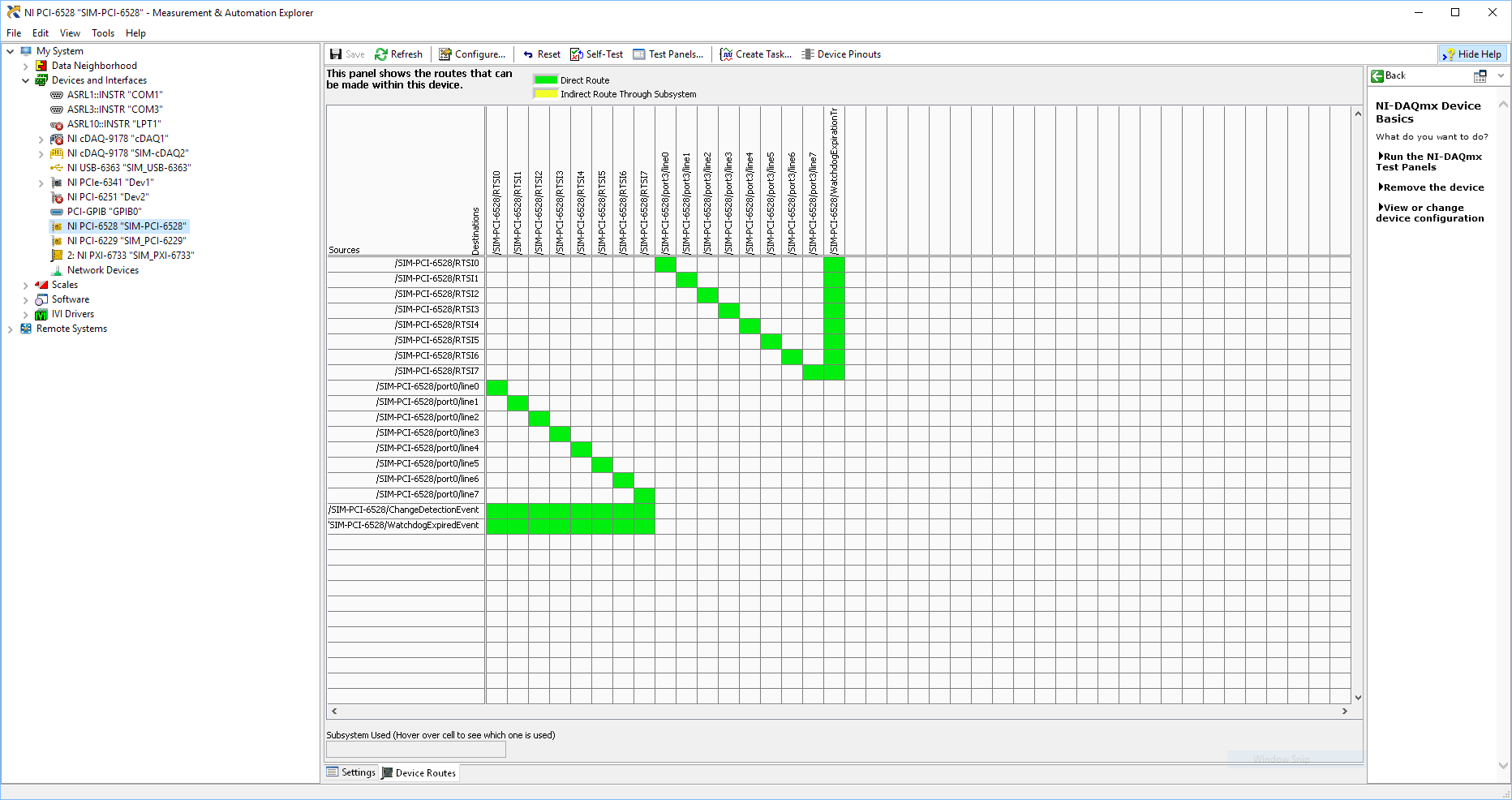
Using SMU 6612 to measure PXI-6528 pulsewidth channel - channel is not available.
Hi all
I use SMU 6612 card counter to measure the pulse width of the signals to PXI 6528 DIO card. These two cards are in the same chassis PXI (NI-SMU-1065). I could measure the pulse widths using the example LabVIEW 2013 Counter - pulse width of reading and (over) frequency example of .vi. However not all channels of the PXI-6528 map appear in the drop-down list of channels on the pulse width can be measured. Try to connect any other channel that those which are available in the drop-down list returns the error. On the PXI card port 6528 0,1 and 2 are entered ports and port 3-5 are output ports. I can measure the pulse on port 0, 3 width and line 0 port 1 and 4.
Can someone explain to me why don't see port 1 or port 2 channels in the drop-down list or force the VI to measure the width of pulse on these channels?
I can plug PXI-6528 external input channels SMU 6612 counter input channels and measure the pulse width, but if possible I'd like to avoid the external wiring between the 2 cards.
Probably not. Unless the routing plan is in fact reversed as it seems a bit sorta that. As stated on my system, you can route * of * a port of entry * to * RTSI, or you can route * of * RTSI * to * one output port. This does not make much sense to me, but that's what I see:
If the routing card * is * reversed, your only likely workaround without physical wire would be to generate impulses in question of port 3. It's pretty clear that 1,2,4,5-tetrachlorobenzene ports have no ability to interact with the bus timing, physical wiring would be the only option.
-Kevin P
-
PXI-1033 not detected until the pc is rebooted
We have a chassis NI PXI-1033 with a PXI-5114 and PXI-4072-PXI-6221, fist, that he had failed to recognize and install drivers for motherboards. The search in the knowledge base, I tried workaround by disabling the PCIe mode ' bcdedit/set pciexpress forcedisable' command and rebooted the pc. Then the system recognized and installed the drivers for all the hardware.
Disabled the PXI system at the end of the day. The next day, after activating the system, he did not recognize the hardware, returned changes to aid 'bcdedit/set pciexpress by default', then restarted the pc. Once again the material have been recognized.
I tried to change the configuration on the PC BIOS, without success. The PC is an ACP-4000 of Advantech. We need to restart PC after a cold start so he could recognize the hardware and load drivers.
Is this normal?
Concerning
The PC is under Windows 7 Pro. I searched on google for similar problems, where I found one where someone said that the culprit is that the chipset of the motherboard not give not the PCIe card delay what he needs on a start cold in order to be recognized. A reboot gives the time required and the card works.
Maybe you are looking for
-
My computer restarts when the awakening of suspension
It's a mobile Athlon 64 with Windows XP (32 bit) and SP3.When I press the suspension button or select suspension in the stop menu, it suspends its light flashing and all. Problem is: when I move the mouse or press a key any wakes up, it starts window
-
I just had my first app in Blackberry App World. I also got the email to offer them for free the Playbook, and I filled the form of delivery. I wonder if I need to code-sign my application in order to receive. Any help you can give me would be greatl
-
Writing tip of the day, using php 5.
-
Loads of computer in the temporary profile
Original title: help please I have a temporary profile on the new vaio. You lose all my work on this profile, or when it is fixed.
-
Accident to ingest if SpeedGrade file is located in the directory
Hellojust installed last CC on a clean install win 7 / x 64 machine and face the bug where the prelude crashes on ingest.so I searched a bit and found a lot of people with this problem. Here, on my PC, it seems that as soon as a project file SpeedGra