PXI automotive "in analog.
I'm moving the car test of our company in the 21st century - far a mess of Measurement Computing and Dataforth and PXI system modules of NOR.
Anyone used PXI to read into signals from 12 to 16 volts? For the moment, I can only find analog input modules with +/-10 volts range. I'm stuck test signals running in modules Dataforth to step-down in +/-10 volts?
Crucial importance is the controller? Can I use an Chassis NI SMU-1073 with PCI Express controller and cable (3 m) for the resolution of 1 millisecond for the collection of data and control?
Thank you
Ron
Hello Ron,
There are several modules that will be tailored to your needs. Please see the link below. Several of the modules will work for your application. Since you need only measure the voltage between 12V to 16V range, you only need a range of 2 Volts negative to positive range 2V. Technical data sheets will give you the absolute range you can operate the device inside.
 FSLASH-XI-Co...
The controller is not critical for the data collection and control for your scenario. For your application, the module and the chassis will be critical components.
I recommend you contact the sales department OR to get great recommendations if you have additional questions.
I hope this helps!
Tags: NI Hardware
Similar Questions
-
How can I use my PXI-6115 meter analog signal trigger to generate pulses of frequency
I work on a PXI-6115 DAQ card and want to using the analog signal to trigger the counter it's generating frequency pulses. The manual says the analog trigger is supported, but I can't use an analog signal to trigger the start of work, in the test, I use the counter 0 to generate pulses and use the signal input port analog trigger PFI 0, can someone tell me what it is? My test VI. & error message appears in the attachment.
Best regards
If you read the error you can see digital triggers are the available trigger only when you use the output of the counter.
You can work around this by setting up a dummy analog input task which will trigger an internal digital triggering when he sees the right analog trigger.
See this thread for more details:
-
Full scale PXI - 6254 DAQmx Analog Input
Hello
I use PXI - 6254 Board to read the analog inputs. Configured channels using DAQmx create Channel.vi with sub parameters.
In the configuration: CSR
Min: 0
Max: 10
Units: Volt
I read the channel using DAQmx Read U16 2D with the sample of 1. I expected below the values.
data of 0 v = 0
10 volts = 65535 data
but it gives 10 volts = 31544 data. Please let me know why.
If I set up the channels with the settings below:
In the configuration: CSR
Min:-10
Max: 10
Units: Volt
He always reads the same values (data 0 v = 0, 10 volts = 31544).
Please let me know, how I can get 10 volts = 65535
Thank you
Hi LVTestek,
The PXI-6254 is not an interval 0 to 10 V input V. The specification of 625 x OR lists the available input ranges:
Entry level of ± 10 V, ± 5 V, ±2 V, ± 1 V, ±0, 5 V, ±0, 2 V, ±0, 1 V...
When you set Min = Max 0 = 10, DAQmx chooses the smaller input range that allows to measure signals between 0 V and 10 V without clipping. On the PXI-6254, the smaller input range that meets this criterion is the range of ± 10 V, where - 10 V corresponds to-32768 0 V corresponds to 0 and 10 V corresponds to 32767.
However, there is an additional complication: ranges entry on M Series devices are slightly wider to accommodate the software calibration. Otherwise, gain of a device could reduce the scope of actual entry, and offset error would move the ends of the effective input range. If the [-10 V...] 10 v] range on your PXI-6254 could be more like [-10.3 V...] 10.4 V]. 10 V is actually to 31544, rather than 32767. On another PXI-6254, 10 V could correspond to a different value of gross / scaleless and 31539 31552.
Another side effect of calibration of the software, is that the data returned by the flavours 'raw' and 'no' to the VI DAQmx Read are benchmarked. The KB explains further: is raw data DAQmx calibrated or chipped?
If you can modify your application to use one of the flavors "on the scale" (F64) VI DAQmx read, which should save a lot of effort. If not, could you explain why your program requires readings without scales/bullies? The right approach depends on the requirements. For example, if you want to save the data in a file and you need to reduce the file size by using raw data / scaleless, configuration DAQmx to save data directly a TDMS file can meet your needs. If you update an older application to work with DAQmx and M Series, a different approach may be more appropriate.
Brad
-
Synchronize PXI-8512/2 and DAQ, PXI-6220 CAN
Hello
I read some examples and other posts on the topic "sync", but I need more information.
I'm using a PXI-8512/2 with an older application, based on the API of frame. Several frames are transmitted and received periodically, and I need to enter a unique ID of arbitration which has a cycle of ~ 5 ms.
At the same time, I need a task of data acquisition (analog input) with a sampling frequency of 1000 Hz.
The challenge is, I need to have the same time base for the analog input and CAN.
As far as I understand, the timestamps CAN are created in the PXI-8512. The timestamp of the start of the DAQ tasks is based on the time of OS (Windows).
Transmission/reception CAN must be running still (to perpetuate the ECU), and the data acquisition task will be triggered manually.
I found the example '\nican\Frame - base with NI - DAQmx.llb\CAN Frame entry API DAQmx Input.vi'. It fits my needs? There is a comment saying: "the departure of AI uses the same sampling as CAN. What it means? The sampling frequency of my CAN is fundamentally different from DAQ. But I have to be able to associate each sample DAQ for a CAN of armature (same time base).
Thank you for any information helping to clarify.
Concerning
Hello
Sorry, I don't know why I thought you had an X-Series. There is also an example for the other series with the XNET driver:
Synchronize PXI - CAN with analog DAQmx of entry (using the PXI-Clk10) .vi
Kind regards
Heinz
-
Error in the capture of several channels using pre-trigger
I have problems of acquiring data with pre-trigger samples during the capture of several channels, using hardware NOR-PXI-6071E and Analog Input VIs in Labview (inheritance OR-DAQ).
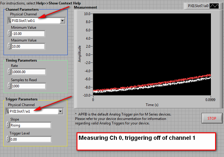
My goal is to trigger a signal, while capturing another. Unfortunately, I can't use the PFI0 for external triggering, as our cables/material have already been built, so I have to use an analog input as the trigger channel. I understand that to do this I must capture the two strings and the string I want to trigger outside must be the first string in the list.
If I trigger and capture on the same channel (I tried 1-4) then it works very well, regardless of the number of samples before relaxation together. If I capture more than one channel (the channel of the relaxation to a first), with no pre-trigger samples, then trigger and capture both work very well. However, if I do the same thing with pre-trigger > 0 sample I get the following error:
Error-10621 to AI control. Possible reasons:
NOR-DAQ LV: The specified trigger signal cannot be assigned to the resource for the trigger.I don't have to such limitation explained in the user manual, and the forum search, I found a few other people who have had the same problem but they had no solutions. Any ideas?
Hi Jackson,
Unfortunately, this is a hardware limitation when you reference analog trigger via one of the lines to HAVE.
Please see this knowledge base. Particularly the second paragraph says
The error-10621 appears immediately when the VI running if you try to assign scans of relaxation before while scanning multiple channels and using one of the entries as your trigger channel.
Details are explained in the third paragraph:
Because all the entries are multiplexed before being sent for analog triggering circuit, it is possible that the trigger on the trigger channel conditions might miss while the device is multiplexing by another channel. In this case, the trigger will not be detected.
It is explained in the E-Series user manual page 10-3. Specifically the second paragraph of the section entitled "Analog Input Channel".
Eric S.
-
PXI-6071e offset drift on the analog inputs
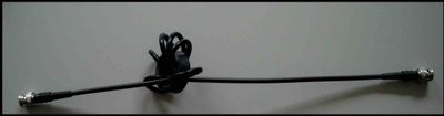
Hi, I have three cards PXI-6071E, sitting in a PXI-1042 chassis that is controlled by a computer with windows XP. The 6071Es are connected to the SCB-100 break out boxes that are wired to a pannel of BNC female Panel Mount on twisted pair.
I noticed that all of my analog inputs will drift around-10 V to + 10 V if they are not connected to what whether forcing them to a certain tension. This has always happened. We also see a bit of crosstalk between channels. For example if I open a panel of test in the measurement and automation Explorer I can watch the voltage read on the drift tickets through their full range, and alteration of the signals on nearby channels will appear on the channel, I am able.
Is this just standard behavior and to predict? Is there something more I could do to minimize this drift and crosstalk? I am trying to reduce noise in my system so I figure optimize my DAQ could not hurt.
Thank you
With nothing plugged into the catch to high impedance, drifting you see is quite normal. The front end of the circuitry builds up a charge, crosstalk is proabably due to the multiplexer input (did not check but I think that the 6071 has a) transferring the load to the other channels when they are analyzed.
Search the Forum of ghosting, you will find related discussions.
-AK2DM
-
Analog input problems using PXI-6232
I tried to solve this problem for a while now without a bit of luck. Solution suggestions are welcome.
I use a PXI-6232 with LabView 8.5.1 to accept signals analog several of my sensors. Based on the signals as a PWM signal is generated and the output using PXI-6713.
Some of the analog input signals have spikes in them, which occur at all times during the tests. I watched the same signals on an oscilloscope - without crampons. I change my hardware configuration, and the spikes still occur in the same places. It seems that the program makes some resets resulting in measurement errors.
I have attached the VI and a JPEG of measured inputs.
Thanks in advance
Concerning
Vadim
I was first confused of your time scale
 but it seems that these spices occur every 20ms (not s) what to a line 50 Hz noise due to switching power converters (or a diode without compensation bridges
  )
)Another clue was the measure of the scope. While using the application scope, you opened a groundloop so the spikes because of the dI/DT through the groundloop are another way to get around.
So I'm pretty sure this isn't data acquisition (in this case) this is your configuration.
Provide a cleaning (low R AND L low) path of power (keep them close and twist slightly if possible), add a filter to down the dI/dt, identify the ground loops. (Use your scope with a little as a sensor at the entrance to reel and catch magnetic fields can open eyes)
THEN to clean the last ears (on the acquisition of data) to get the last ppm use selfs
-
PXI-6070E, how can I configure which are two analog input pins?
Hello
I'm reading 3 analog signals using PXI or 6070E simultaneously. I'm looking for on what axes correspond to what analog inputs? It's the same thing all the time, or should I set up?
For example, currently, the pines 68 and 34 are the + and - of the AI0 channel. But I can't find the rest.
Thank you.
How you are looking for the list of the pins? Look in the manual or in MAX, right-click on the device and select 'device pinouts. Ai0 is 68, ai1 is 33, ai2 is 65. The pins do not change. What changes is ending the pins to use if differential or single acquisition. For example, if you purchase a differential signal with ai0, you use pins 68 (ai0) and 34 (ai8).
-
How can I display an analog input for the PXI-5105 on LabVIEW?
Hi all
I am very very new to LabVIEW and I started to tinker with it. I use the version of LabVIEW 2010 SP1 on Windows 7 OS. I also have the chassis NI SMU-1073 with SMU-6361 and PXI-5105 modules and the chassis is connected to my PC via PCI. I became familiar with the devices and trying to see some analog signals to one of the channels on the PXI-5105 module in a graph in LabVIEW.
I would appreciate your help.
Hello Henokview!
I would like to read through these tutorials to understand the steps of programming of the NOR-SCOPE, NOR-DAQmx. After reading these links below, you will be able to understand how to connect the output of a readfunction to a chart or table.
DAQmx
http://www.NI.com/white-paper/5434/en
OR-SCOPE
http://www.NI.com/white-paper/3382/en
Best regards
Jonas
-
Timed by analog material out with PXI-6733
Hello
I'm a little confused on the possibilities for the material of analog timing of release of a PXI-6733, using pulses of DIO to a separate device.
I want to generate an analog voltage on the signal for synchronization from another device.
Lets say I want to generate tensions: 0, 1.3, 8, 0 volt. Sometimes 1 US, 402 U.S., 1004 US, US 1503. (we = micro seconds). I DIO card that will generate TTL pulses in these moments there and let's say I have the latter on a trigger PXI, PFI line line or enter the map of 6733.
How to configure DAQmx with labview to perform this task?
Thank you
Paul.
Hi Paul,.
There are many ways we could do this. The first thing that comes to mind is to sample AO clock battery LIFE of your device. All you have to do is do an array of doubles with the values that you want to scroll through and then then whenever you get a clock pulse we will update the output. You can see examples in LabVIEW by going to help > find examples. "" "The NOR example Finder will appear, and you can find many useful programs in input and output material" DAQmx "analog generation ' record of tension. To achieve my method, I opened the Gen Cont tension Wfm - Ext Clk.vi example and modified the code as indicated. I have included the code here for your reference. In my code, I plug my external clock in the clock via PFI0 source on my card. Now, whenever I get a pulse I will update the output voltage of 1 to-2 to 3-4, 1-2, etc., ad infinum.
-
How do I synchronize pxi-6341 analog output to the analog in pxi-4304
I have an SMU-1082 chassis that contains a high-6341 and a PXI-4304 module. I went out a sinusoidal signal of pxi-6341. AO.0 channel for the pxi-4304. Channel ai.0. The pxi-4304 isn't receiving all signals up to about 75 MS later. How can I synchronize synchronization between the 2 modules together to stop this loss of data?
(Finally, I run a waveform digital off the 6341 and in a device while the 4304 captures analog response from the device. "So I'll need to have all sync'd up).
Thank you for your help,
Ron
After trying many "tricks" with various DAQmx screws, I finally found the solution. I simply had to stagger the 'task to start DAQmx' between the entry and exit, as shown in the attached photo.
Hope this helps someone.
-
PXI-7831R configuration as analog inputs
Hello
I'm new on NI PXI, thought that I've worked on Labview. My PXI chassis has two modules analog output (PXI-6713 and 6733), a PXI-2501 FET multiplexer, a PXI-4070 DMM, PXI - 8464, an IEEE host module adaptation and the module a PXI-7831R reconfigurable i/o () .
I was able to properly configure my components using MAX.
The problem that I do exactly face 'takes analog input' using my PXI chassis.
With the modules above, I suppose that I can use the 7831R as analog I/o module.
But the problem is the 7831R is a FPGA module and it is not displayed in DAQmx.
So, where can I exactly find the analog 7831R pin (in the labview GUI) and how to use them in my block VI?
The next version of labview provides an interface to data acquisition even for 7831R? (my version of labview is 8.2.1).
Kindly help me to solve my problem.
You need the- module FPGA.
-
How can I change the configuration for the output channels analog on a PXI-6704?
I can't seem to understand how to access the configuration of the channels to the outputs analog (channel 33 and 35) for PXI-6704.
This piece of test equipment is out of tolerance and must be calibrated.
I have followed the procedure of calibration http://www.ni.com/pdf/manuals/374081b.pdf, but am getting hung up on step 8, where it is said to repeat steps 4-7 when changing the _cal_ao_current_offset. I can't figure out how to open this channel because it is not listed as a physical channel for step 5.
I'm using Labview 7.1
Thank you
Hello! What you need to do is to add 'Internal channels' to your list of channels, so you can choose the _cal_ao_current_offset or _cal_ao_voltage_offset. This is done through the drop-down list channel right click and select "I/o name of screening...". ». There will be a check box that says 'Internal channels' and will provide you with all available internal channels to enter your vi Create Channel. I have attached some photos illustrating how to do. See you soon!
-
Hello everyone,
I am currently having a grip on analog option trigger PXI 4472 Council. I found on this forum a few years ago an engineer designs OR the vi ' "(attached here) Acq Cont & chart voltage-Int Start of Clk-analog as a good starting point to become familiar with the option of analog trigger for this Council.". " The VI seems to be starightworward for my level of knowledge on Labview base, but apparently I'm missing something.
Here's my problem, as far as I understand in the manual, I can use a 8 ports on 4472 as input for analog signal that can function as a trigger. In the code, edge DAQmx start analog. VI requires the source of the "APFI0" command and the help file, it should be a virtual channel through which signal will. I created the virtual channel named "APFI0" and ai0 connected to it, but I get the error message:
{Error-200265 occurred at DAQmx start Task.vi:1 Possible reason (s):}
Attempted to use an invalid trigger analog source.
Make sure you specify the command source is the name of the virtual
channel of the job or is the name of a terminal that is not readable which
the appliance can use as a source of analog control.
Property: Start.AnlgEdge.Src
{Value: APFI0}I'm guessing that I'm not quite following how the dedicated line for the trigger is initialized. On the fron VI Panel, it is mentioned that the APFI0 is called a standard pin for M-type unit, that I (6221 PXI with BNC-2110 block), but I don't intend to use it as an analog input.
Can someone suggest how to approach this problem correctly?
Thank you in advance,
Oleks
Hello Oleks,
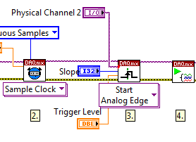
Maybe this will help. On the block diagram, make another copy of the list of physical channels and connect to the trigger on the DAQmx Trigger.vi Source input. There will be a red dot of coercion, but it will ensure that you get the right format for your relaxation.
What is the way analog, you choose to use a trigger, make sure it is included in the task, as below:
-
I am trying to simulate a radiation of 3 mV/V power pressure transducers (excitement is + 10V, full range should therefore be 0mV at 30mV). I am looking for a PXI analog output device high number of channels (PXI-6723, possibly) who doesn't have the down side of the analog output channels linked to the land of installation (differential channels of AO). The plan was to use a voltage across the divider circuit of +/-10V output card AO to +/-50mV. I use a card AO 16-channel, 12-bit which has all the Commons AO related to the mass of the PXI chassis and Earth installation. The DC of the signal part I want it, but there are about 80-100mVpp of noise (from the ground connection) riding on it. I also tried a PXI-6115 card we had at hand and its reference AO are related hard chassis-same result with the noise of the Earth. Is PXI - 6723 AO GND isolated from the land of the chassis/installation? Even if all GNDs AO are shared on the Board, this solution should be much better than having a noisy ground reference.
Any ideas? Alternatives to simulate a floating, the millivolt output device?
Thank you!
The reference of the AO of the 6723 relates to Earth; pages exit track to track analog insulation research, only a handful of AO devices have an isolated field (the business is a low channel count).
-Ciao
Maybe you are looking for
-
[X 200] MUTE button and bluetooth does not not after installing Windows 8
Recently did an upgrade on Windows 7 site to 8.1 and have pretty much everything works except the button mute and Manager connections (and thus bluetooth). I tried to install the latest driver button support page for Windows 8 X 200, and while I saw
-
Unable to validate a way out of trust on either of the two domains using Windows Server 2008 R2
I have two domain controllers in the two different forests. Both have a Stub dns setup for each other and can ping both the field and the name of dc for eachother. Domain1 build outgoing approval and validate successfully. Domain2 see confidence a
-
I'm downloading Panda Antivirus and it tells me to remove Microsoft Antivirus before installing. How do I do that?
-
I ordered a Dell 430 with 10 14 expected delivery date. Delevery scheduled tomorrow on 15 May. I was please with one day to go. Just got an email saying due to excessive demand that your date of delivery is delayed. New delivery date of June 15. What
-
Bought a Dell Inspiron 570 64-bit running Windows 7 home preium and syncing up does not work.
When I try to sync up, I get a message that syncUp stopped working and there is a problem with windows.