PXI offset 5105
Hello
I'm using a PXI-5105 with LV SignalExpress.
I want to measure the tension of the card system with power supply of 5V.
I want to set the offset, but when I put a value, I got the error:
«Requested invalid baseline shift.»
Is the range of voltage: 5V
Offset is: 4V
The impedance is: 1Mohms
What's wrong?
Best regards
Nicolas
Hi Nicolas,.
Unfortunately, the 5105 NOR support the shifts of power. For a quick overview of the features supported, seefeatures supported by the device of scanners using high speed. Best regards
Tags: NI Products
Similar Questions
-
PXI SFP 5105 configured Vs Acquisition VI
Hello
I recently started to use the NI PXI-5105 cards, I need to capture (noise level<20KHz) on="" top="" of="" my="" dc="" signal,="" i="" used="" software="" front="" panel="" to="" capture rising="" edge="" of="" an="" analog="" signal i="" was="" able="" to="" capture="" signal="" when="" it="" meets="" my="" trigger="" requirements="" same="" as="" configured="" acguisition="" example="" vi="" also="" vi="" recommended="" input="" signal freq="" ="" is="" 100khz,="" what="" changes="" i="" need="" to="" do="" in="" order="" to="" make="" this="" vi="" to="" trigger="" when="" the="" noise="" level="" on="" my="" dc="" signal="" exceeds="" certain="" point="" can="" anyone="" please="" help="" me="" with="" this="">
Thanks in advance!
Hey djo.
If I understand your description, the best sounds of relaxation as it can be a trigger of hysteresis with coupling AC trigger in order to eliminate the effects of your DC signal. You will then be able to adjust the amplitude of the noise that you are looking for as the level to which you want to trigger off. You can find information about the options available with the help of scanners trigger high speed OR under Fundamentals > trigger.
-
Hello
I want to use PXI-5105 on SMU 1071 chassis for strain measurment by conneting the strain gauge by the to 5105 wheatstone bridge circuit using BNC cables. I'm using Labview for the same thing.
(i) I get the variable noise (0,008 to 0.010 V) with no connection to the input channel.
(ii) I'm unable to balance / minimise the noise to zero by subtracting signal from one channel to another (differential input).
Data acquisition parameters:
Input voltage: 5V by DC power supply
All cables used are sheathed in copper cables
Sampling rate: 5ms / s
Number of samples to read: 2000
We worked on the reduction of noise for a long time. Any help will be much appreciated.
Thank you
Vinod
Hi Vinod,
Keep in mind the accuracy of the unit 5105 is specified to +/-2mV.
Also, you can check that your device has been calibrated on the outside and in his external calibration cycle.
When I watched a 5105 digital signal in a similar setup to yours, I saw the same kind of (about) + / 2mV noise. I don't think this is unexpected. Especially if you let the front end of your digitizer not completed, it could recover the additional ambient noise.
Why you choose to use this scanner for a measurement of the strain gauge? There are several other products OR Lane County and specifically designed for measures of constraint. Here are a few resources:
Strain with gauges
http://zone.NI.com/DevZone/CDA/tut/p/ID/3642
SMU-43xx Bridge Module Product Pages
http://sine.NI.com/NIPs/CDs/view/p/lang/en/NID/208288
Dynamic signal acquisition board
http://forums.NI.com/T5/dynamic-signal-acquisition/BD-p/100
-Andrew
-
two drivers of PXI chassis with Configuration problem
Hello
I have two PXI chassis. One is PXI 1033 and works perfectly with the NI PXI-5404, 5105, 6509, 1409, installed 8336. The other is 1036 PXI with the PXI-5404 NI, 8366 installed. When I was trying wreath connect, as master 1033, 1036 as slave, I found several problems.
1. in the Measurement & Automation Explorer, does not have my good guys in 1033. Instead, there is a sign of the Red Cross in bottom right with 6509, 5105, 5404.
2. I can't find an another 5404 of the 1036. In fact, I can't find 1036 in MAX.
Update BIOS. My PXI system is already identified under the name 'NOR PXI - 1033 Embedded MXI Express' and Chassis1 is identified as 'NOR PXI 1033'.
So I made several tests as below:
1. unscrew the 5404 1036 slave. MAX can configure 2 1036 chassis. Ok. But when I reconnect 5404 in 1036, same result happened as stated above.
2 uninstall the driver of 5404, so the 5404 in 1033 does not either now. And then reboot again, same result happens again. Cannot detect the 1033 chassis. Other vouchers in 1036 don't work either.
Please, any suggestion is highly appreciated.
Sincerely,
Bin
Hi Ben,
This happens sometimes with MXI-Express:
Error code 12 with MXI-Express
http://forums.NI.com/T5/PXI/two-PXI-chassis-connection-with-configuration-problem/m-p/1475876#M9033
In general, you can read this error 12 means on Device Manager:
Explanation of error codes generated by Device Manager in Windows XP Professional
http://support.Microsoft.com/kb/310123
If it was a problem of bandwidth, PCI or PXI side, you could pull a few cards to see if that alleviates the problem, or that the link from Microsoft over the States, you can disable the driver for other cards.
-
PXI-5105 clipping voltage to ~ 19V
The PXI-5105 should be able to measure voltages of Ridge Crest of 30 V. I have a set of 3, 9V batteries to give me a total of 27 volts through a resistance. PXI clips this tension about 19V however. I confirmed with a multimeter I have 27 volts. I have a value of 1 Mohm input impedance.
Thanks for any help.
Hi cuxcrider,
The maximum range of 30 V on the 5105 is a peak to peak voltage, which means that the higher voltage, it can measure compared to ground (0 V) is + 15 V, except if you apply a DC offset, which unfortunately cannot be done on the 5105 OR. Generally, you will see a little higher than the specified value rail voltage, but generally you shouldn't play in this region because you may cause damage to the Board of Directors and measures out of spec. hope this helps,
-
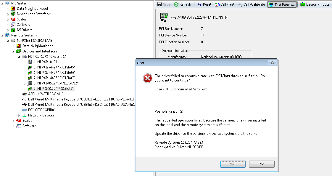
I am setting up test bench and just add a PXI-5105 card to my chassis SMU-1078.
I currently have NO-SCOPE 14.1 installed on my PC host and target RT.
When I try to run the Test panels in MAX, I get the following error:
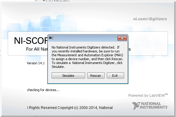
If I try to launch SFP-OR-Scope, it does not detect the card of the scope:
The map seems to indicate as normal in my remote systems in MAX.
For the host, the Installation of NOR-SCOPE includes:
- Configuration support 14.1
- 14.1 development support
- 14.1.1 duration
For the target RT, Installation of range OR watch as 14.1.0.
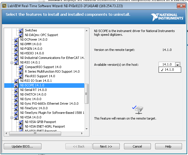
I even checked in the feature add/software for the remote system see if a driver incompatibility was actually present:
I have also confirmed in the Readme that PXI-5105 is supported OR-SCOPE 14.1.
I'm kind of dead in the water on other ideas to investigate on concerning the system is behaving properly with the new card. Other ways suggested for study?
I continued to play with setting up more and find my VI has been targeted my Windows host instead of the goal of the RT. I'm nowable to see my map of scope 5105 now through Labview + RTM. Thank you for tolerating a newbie.
-
Hello
I send the same question last Friday.
The scanner we use is an error occurred.
We use the wondows computer 8, running the program Max.
The error code is 200313 self-test occurred.
Hi derives1,
Here are some steps you can take for troubleshooting:
-Try the card 5105 in another location in your chassis or even in a different chassis, to ensure that it is not a problem of chassis.
-Make sure the version of NI SCOPE you are using is compatible. You can update to the latest version, make sure just that you check the compatibility. http://search.NI.com/nisearch/app/main/p/bot/no/AP/tech/lang/en/PG/1/SN/ssnav:NDR/q/NI%20scope/
-Force Windows to re - detect the device and driver. To do this in the Windows Device Manager to remove the device, and then click Action > search for new devices re - detect the hardware.
Error-200313 from the PXI-5105 often results in an RMA number (Return Merchandise Authorization) to repair the unit. Try the above steps, and if the card still gives you the same error then create a service request, then you can work more closely with an Applications Engineer to start the RMA process.
In addition, I can't find the post you mentioned last Friday, but we ask as a policy forums OR you post once on a problem. This will keep things like organizaed as possible!
-
error "device could not be calibrated" to PXI-5105
Hello
I want to calibrate my PXI-5105. But I get an error in MAX and a calibration vi. I tried to install NO-SCOPE 4.1.3 on PXI, but that does not solve the problem. I have labview time real 13.0.1 installed. I enclose the error messages.
See you soon,.
Syed
Syed,
So there is not a lot of good information on this error. Automatic calibration works by connecting a known signal that is embedded in the digitizer at the ADC and to adapt the constants and phase shift. The 234107 error means that there is a problem with this calibration signal or the signal to the ADC path, etc. This known signal is calibrated during the external calibration and since your device is off external calibration (calibration necessary since February 2011), the problem is probably the calibration signal drifted too far from its known value.
To resolve this problem, you will need to send the jury in external calibration, and I would recommend National instruments, send it because if there is a problem with the hardware with the Commission, we might be able to solve this problem, as well as of him have calibrated.
I hope this helps.
-Nathan
-
Extract and save all the channels of the PXI-5105 with 4 M of edge detection... Help!
Dear collegaues!
Please help me to improve my request, exhibit attached and sorry for my English.
So my task is to extract and save all the channels (eight) of the PXI-5105 with 4 M of detection of peaks and sample rate 4 M with loop 1 sec...
Entered all my channels are wiring detectors NaI with 0, 5... 1 microsec pulse (really) width and 0 kHz at not more than 40 kHz freq.
Why I chose the registration of 4 M and the sampling frequency of 4 M namely? Answer is that I tested previously PXI-5105 40 kHz generator and pulse width 0.5 microsec. It works great and detection of peaks indicate 40000 pulses/s for me. If I set lower than 4M record and sample rate of 4 M, it is without work. In my honest opinion record 4 M and the frequency of sampling of 4 M are parameters very min.
In the detection of peaks time present only 6 working channels... When I connected to diagram more 6 "detector.vi peak" - I see the error "...". out of memory... ».
Advise me please, what needs to be done to it, it's all working well.
-
Unable to trigger pxi-5105 exported signal pxi-4461
Hello
I use a chassis PXI-1033 with a PXI-4461 (daq) in slot 2 and 4-PXI-5105 in slots 3-6. I want to use the 4461 to export a reference trigger signal to of the 5105, but when I try to run my program I get the following error:
Error-89126 occurred at DAQmx Read (Analog DBL 1Chan 1Samp) .vi:1
Possible reasons:
Trigger line asked could not be booked because it is already in use.
Property: RefTrig.OutputTerm
Property: RefTrig.Pulse.Polarity
Target unit: PXI1Slot2Task name: _unnamedTask<89>
The Subvi I use to export the signal is built off an example I found. At the moment it is only under the scope of my code mode (I'll take care of the datalog part later). I'm not sure what I'm doing wrong, any help is greatly appreciated.
Thank you
John
Hi John,.
T Clk select a PXI_Trig lines used to deliver pulses of synchronization between devices. Since that you configure T - Clk before configuring the signal to destination, the driver doesn't know that you plan to use PXI_Trig0 to export the reference trigger. I guess that's to select PXI_Trig0 as the line to book the pulse of synchronization.
I recommend that you try to export the signal to one of the other lines PXI_Trig - this should I hope to correct the problem but keep inform us if it is not. Thanks for posting and have a great weekend!
-John
-
Problem of delay time PXI-5105
Hello
I'm running the PXI-5105 (@ 60Msa/s/ch 12 bit 8Ch) using the attached VI. I put it to trigger off channel 0 to 1V. When I put in a sinusoidal waveform of cycle 5, it seems that the scope triggers too late and I only see 4 of 5 cycles. I confirmed this by generating a sinisoid of increasing amplitude across a PXI-5412 and again once the waveform has been truncated, as if there is a delay after that relaxation hit. (btw, I have an oscilloscope running in parallel and the waveforms appear perfectly here)
Why this is happening any help would be really appreciated.
Thank you!
Actually - problem solved.
When I played with him I had inadvertently set it to DC coupling. Coupling AC fixed.
-
How can I display an analog input for the PXI-5105 on LabVIEW?
Hi all
I am very very new to LabVIEW and I started to tinker with it. I use the version of LabVIEW 2010 SP1 on Windows 7 OS. I also have the chassis NI SMU-1073 with SMU-6361 and PXI-5105 modules and the chassis is connected to my PC via PCI. I became familiar with the devices and trying to see some analog signals to one of the channels on the PXI-5105 module in a graph in LabVIEW.
I would appreciate your help.
Hello Henokview!
I would like to read through these tutorials to understand the steps of programming of the NOR-SCOPE, NOR-DAQmx. After reading these links below, you will be able to understand how to connect the output of a readfunction to a chart or table.
DAQmx
http://www.NI.com/white-paper/5434/en
OR-SCOPE
http://www.NI.com/white-paper/3382/en
Best regards
Jonas
-
PXI-6071e offset drift on the analog inputs
Hi, I have three cards PXI-6071E, sitting in a PXI-1042 chassis that is controlled by a computer with windows XP. The 6071Es are connected to the SCB-100 break out boxes that are wired to a pannel of BNC female Panel Mount on twisted pair.
I noticed that all of my analog inputs will drift around-10 V to + 10 V if they are not connected to what whether forcing them to a certain tension. This has always happened. We also see a bit of crosstalk between channels. For example if I open a panel of test in the measurement and automation Explorer I can watch the voltage read on the drift tickets through their full range, and alteration of the signals on nearby channels will appear on the channel, I am able.
Is this just standard behavior and to predict? Is there something more I could do to minimize this drift and crosstalk? I am trying to reduce noise in my system so I figure optimize my DAQ could not hurt.
Thank you
With nothing plugged into the catch to high impedance, drifting you see is quite normal. The front end of the circuitry builds up a charge, crosstalk is proabably due to the multiplexer input (did not check but I think that the 6071 has a) transferring the load to the other channels when they are analyzed.
Search the Forum of ghosting, you will find related discussions.
-AK2DM
-
PXI-5105 resolution not quite as expected.
I have a system with the guidance of PXI5105, and I use it to sample a signal on beach of 30V (+/-15V), 1megaohm input impedance, 1megasamples by the second sampling rate.
The PXI5105 has a resolution of 12 bits, so I expect to see the steps in the quantification of 30V / (2 ^ 12) = 7.32mV
Acquisition of a stationary signal, the noise extends over 7 discrete levels, so spans 6 quantization steps (see file attached .jpg)
Ranges of noise on 52mV (it goes from-16 to + 36mV), so measured quantification step is 52 / 6 = 8.66mV
I'm missing something obvious here. Why the difference between calculated and measured resolution?
My only thought is that resolution is not linear in voltage range. I expect there are a few non-linearity, but didn't expect so much.
Fill the void in my knowledge!
Hi Bandit,
The gap you see is due to the fact that the input range effective from Ridge to ridge of the Board of Directors is not exactly 30V. The overall increase in analog front end that lies between your input signal and the ADC has initial inaccuracies and can also drift over time and temperature. These effects can be minimized but never completely eliminated. As a result, we design boards to have a peak-to-peak input nominal range is slightly larger than the ideal ranges specified in the data sheet. This ensures that the jury will never less that ideal beach, even though the gain of slightly derivatives (this way you can always be assured that if you use the 30Vpp range and put you in a 30Vpp signal you will never saturate CDA which results in a loss of the signal information). The 5105 has an internal calibration of precision voltage generator which is then used to calibrate data at the scale that you are returned. This results in a slight reduction in resolution (increase of the voltage/ADC code) as you have seen, but the tension you be returned is always exact specification of precision AC / DC published in the data sheet. If you know that the resolution calibrated, it is possible to get this information from the output of cluster "wfm info" from the "Fetch (poly) .vi niScope" when you use the vi in a mode of extraction of binary data. Sorry for the confusion and hope this helps.
Kind regards
-Matt
-
When to compensate for and win on a PXI-5122 niScope change?
In my application, I use the niScope VI Fetch (I16 2D) to extract a multi-record, multichannel on a PXI-5122 digitizer acquisition. Trying to optimize my code, this has led me to this question.
I am taking 32 successive acquisitions and adding (on average) all waveforms. According to the notice in the scale and standardization of binary data, I first apply the parameter wfminfo.gain to data I16, sum which, then apply the offset. MATLAB-like pseudocode for my Labview code, it is something like:
sum = zeros (1,1000)

offsetsum = 0

for i = 01:32

    [wfminfo, samples_i16] is niscope_fetch_i16 (...);

    samples_float = wfminfo.gain. * float(samples_i16[0,:]);

    Sum = sum + samples_float

    offsetsum = offsetsum + wfminfo.offset

end

Sum = sum + ones (1,1000). * offsetsum
So my question is whether it is prudent to assume that the wfminfo gain (and offset) settings remain constant for the duration of a session of acquisition (since time niScope Acquisition throw is called until the moment where the acquisition completed)? The reference above on normalization coefficients indicates that these coefficients are a function of resolution and vertical calibration settings. That would allow me to move the multiplication of gain outside the loop of the acquisition and perform arithmetic on integers. It's a safe assumption?
Hi Gregory,
We tested this here, and you should be able to pull these gain and offset parameters before the while loop is entered and the arithmetic operation later outside of the loop. To do this, you can place a niScope get Wfm Coefficients VI before the while loop, set it to obtain the Coefficients of standardization and route those elsewhere, because they will remain constant over the acquisition.
Maybe you are looking for
-
Kernel Panic #2 and another batch of bad RAM?
OKAY this is getting annoying. A few days ago, I posted about a previous kernel panic and if it linked to the bad RAM. My question has been answered by Illaass and Grant Bennet-Alder, the culprit in my kernel panic was bad RAM as Illaass noted The ex
-
Qosmio F750 - need to Win7 64-bit Home Premium drivers
Hey,. I am planning to reformat my laptop and is unable to find the driver reliable downloads on the internet. I searched around for the Windows 7 driver downloads for this part of the model PQF75L-041002, a Qosmio laptop model and have not been able
-
P10 and mpci card WI - FI - hardware compatibility list
Is there a list of internal WI - FI card for P10 compatibility? I do not know what card should I buy to make it work. Best wishesJarek.
-
Could not load file or assembly NationalInstruments.DAQmx
I get an error 'Could not load file or assembly NationalInstruments.DAQmx' when I put my application on another computer. The only difference between the two computers that I can say is that one that doesn't use the 64-bit Windows version and one wh
-
Installer for P1006 stops working
Hi, I just bought a new laptop with Windows 8.1 (64-bit). On the pages of HP driver installation fails in halfway during the installation process. It stops at the entry «Copy of the files on the hard drive...» "and Windows returns"printer software in