Question about digital output continues [C/C++]
Hello
I am elaborating for the NOR-6503 MS Visual Studio 2008, and so far the ANSI-C Chan to dig to read textual examples and write dig Chan are excellent and work as expected. However, wrote to the digital channel by using the example of writing only happens once, and I just need to be able to write constantly of the '0' or '1' (keep in a logic or disable the State as a switch). I was wary to put everything in a while loop, but since I watched the other stamped and counter examples and they seemed to require an additional hardware component; I wanted to know what you recommend as an implementation of a simple software for it. I appreciate your response, thank you.
Thanks for the quick reply - you are right in saying that the VI WriteDigChan must maintain the status of this line whenever the program ends. I did some more research and learned that the reason why I had these performance issues read and write is because on the NOR-6503, you can only configure a port as the inputs and outputs and no individual pins (without resetting the State of all of the port). So whenever I run my program, I noticed the State of the switch switch from low to high for a fraction of a second, but as soon as the program went from WriteDigChan to ReadDigChan, the value has been reset and all I got was 0 x 0.
For any other person who looks at this problem, NOR published an article showing what devices DIO lines can be configured individually:
http://digital.NI.com/public.nsf/WebSearch/FDEE00034B16F5E086256119005DC75A?OpenDocument
Tags: NI Hardware
Similar Questions
-
Question about the Acquisition continues through NOR-DAQmx
I'm a bit new to NIDAQmx methodology and I was wondering if someone could could give me some advice on accelerating certain measures of tension that I do with a case of DAQ NI USB-6363.
I have a python script that controls and takes measurements with a few pieces of equipment of laboratory by GPIB and also takes measurements in the area of DAQ OR DAQmx via (I use a library wrapper called pylibdaqmx that interfaces with the libraries C native). As I do with the data acquisition unit is 32 k samples at 2 MHz with a differential pair to AI0. An example of code that performs this operation is:
from nidaqmx import AnalogInputTask

# set up task & input channeltask = AnalogInputTask()
task.create_voltage_channel(phys_channel='Dev1/ai0', terminal='diff',       min_val=0., max_val=5.)
task.configure_timing_sample_clock(rate=2e6, sample_mode='finite',
      samples_per_channel=32000)

for i in range(number_of_loops):  < ... set up/adjust instruments ... >  task.start()  # returns an array of 32k float64 samples  # (same as DAQmxReadAnalogF64 in the C API)  data = task.read(32000)  task.stop()  < ... process data ... >

# clear task, release resourcestask.clear()del task< ... etc ... >
The code works fine and I can all the 32 k spot samples, but if I want to repeat this step several times in a loop, I start and stop the job every time, which takes some time and is really slow down my overall measure.
I thought that maybe there is a way to speed up by configuring the task for continuous sample mode and just read from the channel when I want the data, but when I configure the sample for the continuous mode clock and you issue the command of reading, NOR-DAQmx gives me an error saying that the samples are no longer available , and I need to slow the rate of acquisition or increase the size of the buffer. (I'm guessing the API wants to shoot the first 32 k samples in the buffer zone, but they have already been replaced at the time wherever I can playback control).
What I wonder is: How can I configure the task to make the box DAQ acquire samples continuously, but give me only the last 32 samples buffer on demand k? Looks like I'm missing something basic here, maybe some kind of trigger that I need to put in place before reading? It doesn't seem like it should be hard to do, but as I said, I'm kinda a newbie to this.
I understand the implementation of python that I use is not something that is supported by NEITHER, but if someone could give me some examples of how to perform a measure like this in LabView or C (or any other ideas you have to accelerate such action), I can test in these environments and to implement on my own with python.
Thanks in advance!
Toki
This is something I do a bit, but I can only describe how I would do it in LabVIEW - I'm no help on the details of the C function prototypes or the python wrapper.
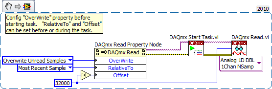
In LabVIEW, there are accessed via the 'DAQmx Read property node' properties that help to implement. One is the Mode "crush" which I'm sure must be set before performing the operation. The other pair is known as "RelativeTo" and "Offset" and they allow you to specify what part of the CQI data buffer to read data from. If you the config to "RelativeTo" = 'most recent sample' and 'Offset' =-32000, then whenever you read 32000 samples, they are the very latest 32000 which are already available in the buffer of data acq. Between the readings, the task is free to overwrite the old data indefinitely.
Note that you will need to do this continuous sampling mode and that you can explicitly set a buffer size smaller than the default which will choose DAQmx based on your fast sampling rate.
An excerpt from LV 2010:
-Kevin P
-
Question about the output format...
I run this command:
Get - vm | Select-Object - name of the property, Notes, VMhost, invited
and the output of the powercli window, only gives me the name column and not others... If reverse the order he still gives me one time as the first property in the list. Now if I run the same command, but the export to CSV all columns show with their associated statistics.
How is it that I can't output suitable for all the columns in the window powercli?
I am running powercli worm 5.5 Rel 1 64-bit...
Any suggestion would be greatly appreciated as im trying to learn powercli...
Thank you!!!
If some properties of container which is long, he pushes the other properties of the screen?
Try like this, you see all the properties?
Get - vm | Select-Object - property, Notes, VMhost, invited name | Format-List
-
Question about the output of the command top in solaris
Platform: Solaris 5.10
In the output at the top of the page, if you look at the colum CPU, you can see that a single process (2415) consumes 95,84% CPU, another (28533) process consumes 91,81%. How can this happen? If a process consumes 95,84, less than 5% of CPU is available to all other processes. Right?
load averages:  4.24,  4.02,  3.89;                    up 57+10:17:11     14:36:35
252 processes: 245 sleeping, 1 zombie, 6 on cpu
CPU states: 40.7% idle, 46.7% user, 12.6% kernel,  0.0% iowait,  0.0% swap
Memory: 16G phys mem, 1002M free mem, 31G swap, 31G free swap

   PID USERNAME LWP PRI NICE  SIZE   RES STATE    TIME    CPU COMMAND
  2415 oracle     1   0    0 6267M 6182M cpu     45.7H 95.84% oracle   -------- ???
 28533 oracle     2   0    0 5245M 5166M cpu     88:23 91.81% oracle   -------- ???
 12062 oracle     2   0    0 5245M 5166M cpu    194:39 82.03% oracle
  3459 oracle     1   0    0 1380K  996K cpu      9:55 73.00% gzip
  2276 oracle     2  35    0 5244M 5165M sleep    0:16 12.84% oracle
 13629 oracle     2  33    0 5244M 5165M sleep    4:51 12.44% oracle
  7784 oracle     2  32    0 5349M 5270M sleep    1:51 11.85% oracle
  5217 oracle     1 100  -20 5248M 5154M sleep   17.5H  3.05% oracle
  5225 oracle     1 100  -20 5248M 5154M sleep   17.3H  2.87% oracle
 14569 oracle     1 100  -20 6273M 6175M sleep   28.0H  1.61% oracle
 14565 oracle     1 100  -20 6271M 6173M sleep   28.8H  1.56% oracle
  1052 root      44  59    0   61M   36M sleep  319:29  1.41% crsd.bin
 15734 oracle     3   0    0   33M   12M sleep  591:32  1.11% tnslsnr
  5237 oracle     2  59    0 5275M 5181M sleep   79:47  0.51% oracle
  5235 oracle     2  59    0 5271M 5177M sleep   81:17  0.44% oracle
multi-core CPU?
-
I have a digitized diagram I need to change. I would like to delete a part or if he'll wipe cover an opaque shape. How do I do that?
Your best bet is to use the 'Editorial' feature in Acrobat. In Acrobat X-> component-> Protection tools-> Mark for the redaction.
See also section 2 of this blog: http://blogs.adobe.com/acrolaw/2010/12/ricks-acrobat-x-redaction-guide/
-
question about delivery button continues
Hi all
I just want to know how can I click on the mouse and do they not release, the follwing function can increase the size of the continuous picture.
Yo gIf you want an action to repeat, you will have to tell Flash to do this over and over again. An onRelease event is just a single event, it only happens once. Your username must maintain the key again and again. Alternatively, you can use an enterFrame method or a setInterval() method, to create a recurring event. Here is an example of using enterFrame:
-
6534 PCI for digital output finished generates a continuous output
Hello
I use 6534 PCI for my application, where I generate a digital output, a model finished variable length in a continuous loop. the code runs without error, but I'm not able to justify the behavior of the map. I intend to use the code inside the while loop as a Subvi and if I change the 'command' at the entrance table during each call to the Subvi, the output should vary according to the directives of the entry of the 1 d array.
But this is not the case, the loop displays the previous value that has been given to Scripture DAQmx. If the control panel is changed the output instantly does not change. It takes a while before the actual output changes. The length of the array command I give is also 88 & 133. When I realize that the output is wrong, I disable the DAQmx write vi by a structure of the case, I would expect an error that the output buffer is empty, but rather the old value is generated whenever the start Daqmx vi task is exectuted without.
My tax any problem is that the output buffer is not get replaced with the new value, but I'm specifyng the size of buffer, performing a registration every time and start the task, waiting until the task is done and the task stop. Each stop & writing should delete and empty the buffer, but I did not understad what goes wrong.
Also, I thought that maybe that orders are put in queue up in the output buffer, acual generation is not as fast as the call of the DAQmx write & start, but if that's the case then even if I stop the vi the generation should be until the buffer is empty, but that doent happen VI, break breaks of generation. the number of iterations is equal to the generated models. If anyone can help as to what could be the problem? fi
nd code attached below.
Hello
If I understand the problem you are experiencing, then the reason for the typical behavior when you run the VI, it is that you are not clearing the DAQmx task whenever you intend to go for a fresh DIO write. You stop just the DAQmx task that seems however to clear the buffer on board space.
With this post, I am enclosing a VI of the sample that should work according to your expected behavior. You can even call this VI as a Subvi and can use it to update the DIO port with a digital model of variable length fees. Another fact that I would like to point out, is that, once you have initalised one table, it is not possible to reduce the length of the array. You can only increase by adding new elements. According to your needs given that the digital model that needs to be updated will be of variable length, each time you cll the Subvi, you must create a freash of appropriate length and feed it as input to the Sub - VI. Inside the Subvi, according to the length of this array of entry appropriate buffer space is allocated.
Do trust this solution help solve you the problem, otherwise do not hesitate to go back.
Best regards,
Sagar G yapi | Application engineer | National Instruments - India
-
Questions about an average of response spectrum and frequency of feeding mode.
Hello
I have a few questions about an average of mode. When I generate a sinusoidal signal from one output to two input channels channel to see if my DAQ card works well and vector averaged in the power spectrum for DFT, the amplitudes was different from the previous one of the amplitude, which was supposed to be 1 v peak. They range from 0.5 v to 0.6 v peak. When the calculation of the average model is RMS, the amplitudes were close to 1. I wonder what are the fomulas of RMS and average vector. Does that mean that I could not accurate if I use an average of vector? In a time of frequency response, why I coherences of difference and the amplitudes using the vector and the mean quadratic value?
Thank you
Ningyu
rico1985,
The differences in modes of generation are as they sound: 1 sample output only a sample writing, N samples will be released however many samples configure you for each entry, and the continuous samples released samples continuously until a specified user action happens (you press the stop button or a logic that you created gets fulfulled). The range of Signal output allows you to set a ceiling high and low level of your output signal and it only affects the quality keeping in this beach. Timing to set a deadline for the time between the acquisition of the sample. If a new sample becomes unavailable before the timeout setting, you will get an error. This is useful for looking at a network, because if the network goes down and you stop getting data from a machine and then you would like to know about it. I point you to those videos that are short tutorials on how to make the most of these actions in SignalExpress.The SignalExpress 3.0 Help file is also your first point of contact for all your questions on getting started. These two resources should get you up and running in SignalExpress in no time. (either by the way all your questions answered using these resources) Bravo!
-
Acquire the values only when the digital output is high.
Hello
I work with test of transistor, whose door is controlled by the digital release of USB6289, related to BNC2120.
Test plan:
Door 1.transistor is enabled for 5seconds, with P0.0 for example
2. then, everything remains off for 1secondes.
3.p0.1 is used as digital output to activate the circuit passing him curent through in the opposite direction, P0.1 goes high for 3 seconds, PS: Gate is off.
4. the same cycle repeats again.
My question is to store values to the output of the transistor when P0.0 and P0.1 goes high, and these values should not change until my digital outputs respective again go high.
I can access transistor by continiously read out my power supply values.
and in the State off I want to read AI0 because at that time, my power supply is off, so that I can activate the circuit to pass the current in the opposite direction.
Again, my question is to gain the output through power value when P0.0 is high and store them until the transistor turns on.
and even for P0.1, acquire the value of output through AI0, when P0.1 is high and store it until it goes high again.
Hopefully, I'm able to explain my problem clearly.
Please help me.
Concerning
Anurag
Think about what States (object:statemachine and determine when to use sequence Structures) do you want from t0... t(n-1), IF DAQmx generates outputs and/or inputs are absorbed and what needs to happen (event timed out), before move you on to the next 'State '.
type def 'enum' with your different States:
- initialize
- wait (the user initializes times (sec) set for States, or whatever and presses button 'Start')
- T0 (generate DigOutputs, store acquired data AnalogOutput (string output number) the register shift, before moving to the next State > user 'set time' must elapse (Note: the wait function allows you to control the rate of execution of loop and allow the CPU to respond to external events and system tasks and avoid using wait functions at the same time an operation of software...))
- ...
- t(n-1) if ' end (made requirement) "> goto 'stop', ' another (not requirement not)" > goto regardless of 'State '.
- stop
- write a text file of data (string).
-
How to synchronize 2 digital output channels that have been created with DAQmxCreateCOPulseChanFreq
Hello
I use peripheral USB6221.
I created two digital output, operating on a frequency of 75KHz and duty cycle of 50%. But I need a period of 1 microsecond between the two channels.
I have craeted the two channel on the same task and guess if I use a delay of 0, the channels will be synchronized, but looking at the scope, the channels are not synchronized. Here's the code I used (I checked also all return codes of coarse and fine).
Thank you
Danny.
Int32 RetCode;
RetCode = DAQmxCreateTask ("", & m_OCtaskHandle);
LogMessage (RetCode, "CreateTask", "");
If (RetCode > = 0)
{
define the first output channel for 1 transmitter (75KHz)
RetCode = DAQmxCreateCOPulseChanFreq (m_OCtaskHandle, "/ Dev1/ctr0", ")
"Transmit1 Line 1", / * name to assign to the channel * /.
DAQmx_Val_Hz, DAQmx_Val_High,
0.0, / * initial delay in seconds * /.
75000.0, / * Freq * /.
0.5 / * market factor * /);
define the second output channel for 1 transmitter (75KHz with 1 microsecond delay)
RetCode = DAQmxCreateCOPulseChanFreq (m_OCtaskHandle, "/ Dev1/ctr1", ")
"Line2 Transmitt1", / * name to assign to the channel * /.
DAQmx_Val_Hz, DAQmx_Val_High,
0,000001, / * initial delay * /.
75000.0, / * Freq * /.
0.5 / * market factor * /);
Describe all channels continuous task
RetCode = DAQmxCfgImplicitTiming (m_OCtaskHandle, DAQmx_Val_ContSamps, 1000 / * I think that NA since continuous * /);RetCode = DAQmxStartTask (m_OCtaskHandle);
Hello Danny,
If you are looking for more output channels of the Digital pulse trains, you can create 1 task of counter that is used as the clock for digital multi-line data output. For this digital task, you will need to make the clock source line PFI for the output of your task of counter. Once this has been done, you will need to create the digital signal for each line of output and write to the card. The example called write dig Chan - Ext Clk will explain how to set up the digital task so that the task has an external clock (the counter). I hope this information helps you and if you have any other questions, feel free to post.
-
A few questions about the colors of Patone
I have a few questions about patone color since it is the first time that I use. I want to use them to create a paper letterhead and business cards in two colors.
1)
I don't understand that no sex is more than coated patone washed out colors. I heard that it's because the way paper absorbs the inkt. That is why the same results inkt in different colors on different papers (right?). My question is why is the patone black no sex so different than black normal (c = 0 m = 0 y = 0, k = 100) or black intense:

When I print a normal document with cmyk, I can get pretty dark black color. How is it that I can't have this dark with patone color black color? Even text documents printed on a cheap printer can get a darker color than the color of Patone. He looks way too grey for me.
(2) a first model, I want to print of patone in CMYK color (since I have like 10 different colors on a page of quick comparison). I know these CMYK colors distinguish the colors of patone and I can't get a representation of 100%. But is there a way to convert patone CMYK values?
I hope some of you can help me with my questions.
Thank you.
You can get shades CMYK Pantone in Illustrator, (Swatches Panel > Open Swatch Library > color books > + PANTONE Color Bridge Coated or lying) but in my opinion, what's the point? If you print to a digital printer, just use RGB (HSB) or CMYK. Personally, I never use CMYK called "equivalents." from Pantone
Pantone colors are all mixed pigmented inks, which are fluorescent beyond the limits of the range of RGB and CMYK in particular. The original Pantone Matching System (PMS) was created for the printing industry. He described formulations of ink pigmented for each of its colors.
Most digital printers (laser or inkjet) use CMYK. The range of CMYK is MUCH SMALLER than many mixed inks, printed on papers either paved or unpaved can deliver. When you specify no sex Pantone ink in artificial intelligence, according to Pantone conversion tables, HAVE "about" what will look like this color on a sheet no bed, try using CMYK. -In my opinion, this has little relevance to the real world conditions and should be avoided in most situations.
If your project must be printed on a press printing with Pantone inks spots, then by all means, use Pantone colors. But don't trust the colors of the screen; rather get a Pantone swatch book and watch real inks on paper lying and uncoated, depending on the stock you will use on the press.
With printing decreases rapidly for inkjet and web printers, Pantone has attempted to expand its relevance beyond the traction-date of publication (in the books and software alliances, with one such as Adobe) his old PMS inks and their supposed equivalent LAB and CMYK. I say "supposed" because even once, monitors RGB and CMYK inks can never be literally equivalent to many Pantone inks. But if you go to your project on a printing press printing, Pantone inks are still very relevant as of the "tones".
I also put my preferences I > appearance of black both display all blacks accurately and output all blacks accurately. The only exception to this may be when you print on a digital printer, where there should be no problem checking.
Rich black in artificial intelligence is a phenomenon of the screen, at least in the Prefs > appearance of Black, you specify also "out all inks like Rich Black"-something I'd do it EVER do so out for a real printing press. Still, I put my black people in artificial intelligence at the "output All Blacks Acurately" during a press release. If you fail to do so, then the press you will see any minor issue registration, with C, M and look at the back, especially around black characters. UGH!
Good luck! :+)
-
question about broker command failover
Hi guys
I have a question about switching to the cmd. For example, I have 1 primary database called stdby3 and 2 databases in waiting who are called stdby1 and stdby2. When I made the transition to the cmd to stdby2 waiting for database, why the old principal database stdby3 becomes not a new database of relief once I made a permutation; In addition the new main and backup databases are not open at the end of the transition process
output screen:
DGMGRL > see the configuration;
Configuration
Name: stdby1
Activated: YES
Protection mode: MaxProtection
Databases:
stdby3 - primary database
stdby1 - physical of the standby database
stdby2 - physical of the standby database
Fast-Start Failover: DISABLED
Current situation for 'stdby1 ':
SUCCESS
DGMGRL > PASSAGE to stdby2
Continue to pass, please wait...
The operation requires the judgment of the instance 'stdby3' on database 'stdby3 '.
Closure of Forum 'stdby3 '...
ORA-01109: database is not open
The database is dismounted.
ORACLE instance stops.
The operation requires the judgment of the instance 'stdby2' on database 'stdby2 '.
Closure of Forum 'stdby2 '...
ORA-01109: database is not open
The database is dismounted.
ORACLE instance stops.
The operation requires the start the instance 'stdby3' on database 'stdby3 '.
Start the instance 'stdby3 '...
Unable to connect to the database
ORA-12514: TNS:listener is not currently of service requested in connect descriptor
Failed.
You are no longer connected to ORACLE
Please log in again.
Could not start the instance 'stdby3 '.
You must start the instance 'stdby3' manually
The operation requires the start the instance 'stdby2' on database 'stdby2 '.
You must start the instance 'stdby2' manually
Successful, the new principal is 'stdby2 '.
DGMGRL > see the configuration;
Error:
ORA-01034: ORACLE not available
Process ID: 0
Session ID: 130 serial number: 45
DGMGRL > "exit";
Oracle@localhost ~ $ dgmgrl
DGMGRL for Linux: Version 11.1.0.6.0 - Production
Copyright (c) 2000, 2005, Oracle. All rights reserved.
Welcome to DGMGRL, type 'help' for more information.
DGMGRL > Connect sys
Password:
Connected.
DGMGRL > see the configuration;
Error:
ORA-01034: ORACLE not available
Process ID: 0
Session IDs: serial number 0: 0
DGMGRL > connect sys@stdby3
Password:
Connected.
DGMGRL > see the configuration;
Error:
ORA-01034: ORACLE not available
Process ID: 0
Session IDs: serial number 0: 0
DGMGRL >
Edited by: user6981287 January 6, 2010 09:27Hello
Replace the sid_name service_name and try reloading the listener.
Kind regards
Delphine K -
Realtek integrated sound card is stuck in digital output
I can't get this thing off the digital output mode. Now I have no sound because all analog ports do not work. Telling me that nothing is plugged. I can't reset the analog speaker because it is grayed in Vista. This problem seems to be very common with computers using Realtek and Vista, just do a google search and see for yourself.
I have a feeling it has software problem between Vista and Realtek. But I really think Realtek is just terrible to began with and should not be put in any period of the computer. If I can't get this thing works here tomorrow I will get a good real map.
Message edited by hn333 on 09/04/2009 21:02I had very similar problems and finally managed to solve it.
Something seems to be borked with drivers realtek about automatic jack detection.
After attempting to use the method described here (easier if you can) http://freeweelee.wordpress.com/2008/12/09/vista-and-realtek-front-panel-audio-not-working-solution/, I discovered that I was completely unable to cut jack detection in audio Manager Realtek (no folder icon).
For those of you who (like me) have no icon file, I managed to find another way to disable the detection of jack.
Using the registry editor, find all instances of ForceDisableJD and change the value from 00 to FF.
After making sure that I got all of them, I was able to reboot and everything works fine now.
-
Qosmio E10: Question about PX1211E-1TVD Toshiba DVB - T USB Tuner
Hey all,.
While the analog TV tuner that is inside my Qomsio E10 is OK for now, I'm looking forward to get a Digital Tv Tuner USB from Toshiba adapter.HTTP://UK.COMPUTERS.TOSHIBA-EUROPE.COM/CGI-BIN/TOSHIBACSG/INDIVIDUAL_OPTIONS_PAGE.JSP?SERVICE=UK&ACTION=SHOW _ATTRIBUTES & OPTION_ID = 109331
And I have 2 questions about this article on Qomsio:
1 MCE (version 2004 on E10) will be able to use this DVB - T Tuner for me to record digital programs in MCE?
2 "Intervideo WinDVD Creator 2 Platinum for Toshiba" (comes with E10) will be able to see the PX1211E-1TVD so?
If not, what software could be used to record DVB - T programs?
Later,.Alcahest
Hi Alex
You will be very happy if someone can give you a precise answer to your questions. I didn't see this before, but it will be interesting to know if it works with my Tecra laptop.
If seek you information please let me know how it works. Thank you!
-
Does anyone have a contact point to raise a complaint about the lack of service from Toshiba? I spent £160 on a TV + Stor.e and did have some problems with it, as you can see from the few posts that I raised. After spending £160 on a point I don't understand why if the forum is the only option to support what he is no Toshiba engineers on this issue, who are able to answer my questions. I do not expect a 24 / 7 hotline for £160 I spent, but it would be good to know that a Toshiba engineer could answer my questions about their products. Especially since it's the second one I had which suffers from a cosmetic defect, I had to stick to feet about it as the Unit came with 4 pads ride around the box. I also have my doubts about the HDMI because it seems to be very sensitive to any movement in the area, causing the connection to remove.
I got a Western Digital box media for more than five years and had no problem with this, the only reason why I changed, it was to make use of the connection to the local network, the HDMI connection and the fact it supported more than file formats. FSR this device was abit of a disappointment for me. So if someone could point me in the right direction, I would be very grateful.
Hello
I can understand that you are not happy with the current situation and usually if you buy a product it should properly expect and do no problem.
As you probably already seen here it s a user to only user forum. This means that you can speak with normal people like you and me and there is no official support from Toshiba.
In your case, it would be best if you contact an authorized service provider or call the Toshiba UK. The phone number, you can find on the site of Toshiba UK Web:
http://UK.computers.Toshiba-Europe.comJust give the guy a call and explain your situation. I'm sure they can give you a detailed answer and if your TV Stor.e + must be repaired or not. When warranty hardware repair is free.
I hope I could help you a little bit :)

Maybe you are looking for
-
Sat. 1400-503, SD-R2102 drive: IDE ERROR #1, cont.
Hello.Therefore, even after the firmware update (1400-503 drive, SAT SD-R2102). Original firmware was 1316, after changing to 1W16, an error message is displayed. The firmware update program cannot return to the previous state, bcs is displaying the
-
HP Photosmart C4280 all-in-one no scan
Although my printer works fine for printing and copying, I get error messages when I try to scan by pressing the button or by using the HP software I use the HP Photosmart C4280 all-in-one with a MacBook OSX 10.5.7 running I connect to the printer wi
-
Unable to play the MSN game - Fitz, due to the error: «E-mail address is removed from privacy»
Original title: MSN - Fitz? Is anyone having problems is past level 27 in the MSN game - Fitz? I got a couple of times, the next time that I logged in, I was at level 27. I asked at * address email is removed from the privacy * a little time to help
-
Everything on my pc appear in double
Everything on my pc seems double. See the double clock and the double time. The icons of programs watch then double. My pc is Windows 7 starter mini computer hp laptop.
-
SLM2048 web interface with firefox 4.0 problem
Updated Firefox 3.6 to 4.0 and now the slm2048 (firmware 2.0.0.8 & boot 1.0.1) web interface problems. I get the following error message: error in Pager.SetpagerHTML String contains an invalid character. Specifically, the problem is hyperlink to othe