read the signals of pressure using signalExpress
Hi, I have no pressure option under DAQMx Acquire-> Analog Input
menu when I add a step to acquire pressure signals in SignalExpress 4.0.
Everyone knows what additional module I need to do? Thank you. Cong.
You may need to upgrade your version of DAQmx. The type of pressure measurement was added in DAQmx 9.1.
Here is a link to our latest DAQmx, 9.3:
http://Joule.NI.com/nidu/CDs/view/p/ID/2337/lang/en
Tags: NI Products
Similar Questions
-
How to read the digital I/o using PXI-7813R?
Hi guys,.
I'm reading a digital signal by using one of the ports in the PXI-7813R. The 7813R has 5 digital ports or 39 lines for playback of digital data. I have connected a SCB-68 as the physical hardware interface for 'plug-in' a 5V adapter, which will act as my signal at the moment.
After you configure the PXI via MAX, I wrote two codes, one for my host pc and the other to control the FPGA through the host. But I think, I can have more complicated or completely gone in the wrong direction.
Any help in the drafting of these codes would be well appreciaetd.
Thank you, Anoop
You need the FPGA to sample the signal how often you expect the device to send the data.
If you write your data in the FPGA for the DMA, then on the side PC you just have to read the DMA. I like to think of the DMA as a queue. It makes it easier for me to understand how it works.
-
Read the motor current by using the controller PXI-7350 and MID-7604
I use the PXI-7350 controller and MID-7604 drive to run a motor drive. I would like to be able to measure the motor current while moving the engines. This measurement is possible? If so, what commands are required to read the motor current?
Hi Casey,.
the 7604 can limit the current to a value that is selectable by the user and you can activate the current reduction if the axis is stopped, but there is no way to read the current engine. If you want to measure the motor current, you must do it with an external device, but due to the current chopping and multiphase, motor control stepper motors is not a trivial task. Micro step mode the current phase looks like a rough sinus with lots of harmonics signal, so you will need to do a true measure requiring RMS of expensive measurement equipment.
Anyway. If you need to know the temperature of the motor you should better measure the temperature directly. The most inexpensive device OR do is the NI USB-TC01, but there are many other options available.
Kind regards
Jochen
-
How to read the Serial Arduino data using labview VISA?
Hi =). Im a beginner work reading data series from an arduino but im facing... Lets do it step by step
I built a voltage divider circuit which gives from output
from 0 to 5V. The output of this circuit is sent to a 0 analog input pin
of a Committee of Arduino Duemilanove.(1) Firstly, I connected the cable to connect to my laptop USB the Arduino.
(2) I went to start-> control
Control Panel-> system-> hardware-> Device Manager. Check the Ports (COM
& LPT). In my laptop I can see USB Serial Port (COM4). Now I know only in
LabVIEW that I must read the data series COM 4.(3) to the side of the arduino, here's the code to read changes in voltage
entered to analog pin 0. The last line of 'delay' determines the sampling
Rate of how we want to taste the output of the voltage divider:int potPin = 0; Select the input pin for the output of the voltage divider
int val = 0; variable to store the value from the probevoid setup()
{
Serial.begin(9600) (9600); Opens the serial port, establishes the rate of 9600 bps data
}void loop() {}
Val = analogRead (potPin); read the value of the voltage divider
Serial.println (Val);
Delay (10);
}I slightly modified the basis series reading writing VI... I have
attached the block schema used with comments. Basically, I tried to read
data series, divide by 1023 and multiply by 5 to graphic voltage
variations of the voltage divider circuit. But Im not getting
the correct voltage output values. The value of the tension just keeps go
0 and coming again, as shown in the photo.Could you guys please guide me on what went wrong?
Thank you!
-you read the data, even if there is no data on the port. If 0 bytes are read => «»
-in the case of false, you resources VISA wired for the output of channel tunnel?
-There is no close VISA at the end of the VI resources
-you're not a loop this VI reading bytes
I added an addaption of your VI that you should give a try maybe

-
Problem reading the worksheet after you use a DLL to write on the worksheet
Hello
I have a few problems reading a sheet DLL created in LabVIEW. The DLL is written in C++.
I'll dexcribe what do the VI in the screenshots:
For DLL_INIT = the first false steps the VI (LabVIEW) values and exports in a DLL initialization.
DLL takes these values and not some und calculation, then wrote the measured values and the new calculated values in a csv file called 'filtered_values' and a file 'filtered_values_complete '.
so, I have two files like this after initialization:1.0000000000; 1.0000000000; 18.8991610737; -3.2940000000; 0.0060000000; 0.9000000000; 6.5806287097; -3.2940000000; 1.0000000000; 0.0000000000; 1.0000000000; 0.0000000000;
So now on DLL_INIT = true.
For the calculation, the next step i read the "filtered_values" - file (LabVIEW), calculate the new values and write in filtered_values (DLL)
And in the "filtered_values_complete" - file I will allways read the DLL entry first, so that I can check later, if the DLL has obtained the values to the right of the front step and then add the calculated values.For i > 0 initialization has been made:
-the VI bed sheet "filtered_values" calculation and rotted the table 1 d in its unique values
-The last seven values in the worksheet have been exported in the dll as well as five new measured values.
-This DLL is still a few calculation
- then it replaces the "filtered_values" - file and adds a new line to the 'filtered_values_complete '.This migth be a bit of confusion, so a small example, afer five steps it loooks like this:
filtered_values:
5.0625000000; 1.0000000000; 18.9300200447; -3.2870000000; 9.7320000000; 0.8997597592; 5.9159054233; -2.6533532901; 1.0000000400; 0.0000000000; 0.8078703403; 0.0000000000;filtered_values_complete:
1.0000000000; 1.0000000000; 18.8991610737; -3.2940000000; 0.0060000000; 0.9000000000; 6.5806287097; -3.2940000000; 1.0000000000; 0.0000000000; 1.0000000000; 0.0000000000;
2.0625000000; 1.0000000000; 18.8330081064; -3.2940000000; 9.7270000000; 0.9000000000; 6.5806287097; -3.2940000000; 1.0000000000; 0.0000000000; 1.0000000000; 0.0000000000;
2.0625000000; 1.0000000000; 18.8330081064; -3.2940000000; 9.7270000000; 0.8999399568; 6.4077416273; -3.1451829134; 1.0000000100; 0.0000000000; 0.9480589053; 0.0000000000;
3.0625000000; 1.0000000000; 18.7932988441; -3.2870000000; 9.7280000000; 0.8999399568; 6.4077416273; -3.1451829134; 1.0000000100; 0.0000000000; 0.9480589053; 0.0000000000;
3.0625000000; 1.0000000000; 18.7932988441; -3.2870000000; 9.7280000000; 0.8998799074; 6.2394046705; -2.9768465052; 1.0000000200; 0.0000000000; 0.8988158138; 0.0000000000;
4.0625000000; 1.0000000000; 19.0445703499; -3.2870000000; 9.7320000000; 0.8998799074; 6.2394046705; -2.9768465052; 1.0000000200; 0.0000000000; 0.8988158138; 0.0000000000;
4.0625000000; 1.0000000000; 19.0445703499; -3.2870000000; 9.7320000000; 0.8998198333; 6.0754981785; -2.8129479844; 1.0000000300; 0.0000000000; 0.8521305805; 0.0000000000;5.0625000000; 1.0000000000; 18.9300200447; -3.2870000000; 9.7320000000; 0.8998198333; 6.0754981785; -2.8129479844; 1.0000000300; 0.0000000000; 0.8521305805; 0.0000000000;
5.0625000000; 1.0000000000; 18.9300200447; -3.2870000000; 9.7320000000; 0.8997597592; 5.9159054233; -2.6533532901; 1.0000000400; 0.0000000000; 0.8078703403; 0.0000000000;So it's good enough that the VI and it works fine until some point when the just VI reads more calculation and x = sheet! There? becomes true.
Most of the time it happens when the csv file is about 1200 lines
Someone knows why this happens?
Best regards
Stefan
Hello
understood, that the error occurs somewhere completely else. the thread may be closed
BR
Stefan
-
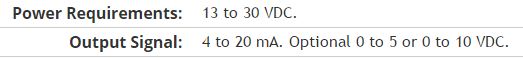
Here is my sensor
Pressure sensorHere's the DAQ data sheet:
Here are my issues:
First of all I don't know what is LO and HI exactly in the DAQ 9219 material.
Second, I don't know what pin code I should connect the DAQ sensor signal wire. PIN 4 or 5 pin? The sensor has three pins, and I guess I should connect the other two wires to the power supply.
Thirdly how to calibrate the sensor. In labview choose voltage in the wizard?I'm pretty new in this acquisition of data and I need your help.
Thank you
Hi SilasIII,
Hmm well 3 sons are probably on the ground, the power and the return signal. The datasheet for the sensor says:
First of all, you need to know which model you have (4-20mA, 0 - 5V or 0-10VDC). HI refers to the return signal, LO essentially means the land of the food that feeds the sensor. Then, you must get the 13-30 VDC supply. I don't think this should be too complicated and can be a simple wall DC power. You can learn how to create a custom in DAQmx scale. I hope that this is a starting point.
Kind regards
Eric
-
Error reading the attached viSA-1073807339 using Subvi, but why?
Hello
First of all, thanks to all who respond!
I read N9020A Agilent MXA Signal Analyzer data. It is successful if a Subvi is used to playback VISA; otherwise "Read Error-1073807339 VISA' rears its ugly little head.» The Agilent gives the message "REQUEST not COMPLETED" just as endearing.
The on error-1073807339 OR Knowledge Base article talks about the need to put an end to the chain of command correctly and explains how to check it by double-clicking the control of chain of command on the front and changing the display of '-' Display Mode of the Codes. I call the VISA Read VI in the block diagram; It does not have a chain of command of front panel control, so I don't know how to apply these tips.
In any event using a Subvi to perform the Read VISA takes care of the problem, but I have no idea why. The VI image that does not work is "Agilent MXA Sig Gen vi.png." A big thank you to Mike on the Agilent forum which provided workaround.
Nina
Mark, Fan of the crows and any other interested person:
I found the error in Agilent MXA GIS Gen.vi. There is typo in one of the VISA WRITE commands. Originally, it was
: MMEMORY
 ATA:? "D:\TEST. PNG"
It should be
: MMEMORY
ATA? "D:\TEST. PNG' (remove: before?)Your comments have been invaluable. Thanks a lot for your help and your patience!
Nina
-
I have more than 200 records - which may be created as text files to use as I need. Can I do this with Thunderbird? Or is completely useless without the Thunderbird program folder?
Thunderbird stores the mail in the Berkeley MBOX format. It's a text format. But change anything and wait for your mail to not display in Thunderbird. Like most text formats. It is fragile when changed manually.
-
Read the PXI-8431 channels using LabVIEW
Hi Marc,
The examples provided with LabVIEW and DAQmx drivers are very detailed and comprehensive to demonstrate how you can use cards. To join the Finder of the example, start LabVIEW and select help > find examples.
When you load the example Finder, make sure you browse by task.
For the programming of DIO:
Navigate to hardware input and output > DAQmx > digital measurement. There is a few screws. Make sure you look in the list of requirements to see the example works with the PXI-6515.You can also visit the following links to learn more about programming DAQmx:
Getting started with NO-DAQmx
http://zone.NI.com/DevZone/CDA/tut/p/ID/5434
Learn 10 functions in NOR-DAQmx and handle 80% of your Applications of Data Acquisition
http://zone.NI.com/DevZone/CDA/tut/p/ID/2835For series programming:
Navigate to hardware input and output > Serial
You will find most of the screw example it can be used with the PXI-8431.I hope that helps you to get off the ground!
-
Save and read the value of control using xml
I need to read and update the controls with the values they have the previous time the vi has been run. Joined a vi that I come up with. I can record control values; When I apply the section which should read and update control values, I get this error "the XML tag describing the type of data does not match the wired type". Do we know why? Attachment: test vi and xml control file.
As far I can tell it seems that you have found a bug. The XML Unflatten handles not properly cluster in a chain, and a variant of something. The Get All method returns an array of clusters, with each group being a string and a Variant.
If you follow these steps:

no error is generated.
But, if you do this:

you get an error.
Looks like a bug to me.
-
read the serial port management using the SRM Protocol
Hello
I have a gas analyzer that communicates with the PC via the serial port.
This is the "Industrial VarioPlus SRM".
I have attached a PDF file that describes the communication protocol.
I'm trying to decode the data that are sent from the parser, but I can't do it.
I have attached the vi in which I made some effort.
Any help is appreciated, at least for a single value in the data stream.
Thank you.
-
Hello
Im trying to understand our noise of a laser. My setup is Laser - detector-Oscilloscope. I read the signal using a GPIB and Labview program. I think that I must take the FFT of the signal produced but it gives me nothing. I plugged the output signal to the FFT.vi and the result is a peak at 0 (zero). I should al least see peak around 60 Hz (light), but I can't. My sampling rate is 100Ksamples per second. Also, how can I see frequency on the x-axis of the curve of the FFT and what is Y Chart FFT plot?
Thank you
Yes. Without information from dt, spectral analysis function will assume a sample rate of 1.
-
How to read a signal of temperature continuous of a pyrometer via RS - 232
I am currently reading and chart of a pyrometer Pyrofiber Lab that arrives via an RS - 232, a continuous signal cable. As much as I know there is no device driver for this instrument (or any other pyrometers).
If I the pyrometer measures alone I can get these in LabView using the Assistant Instrument i/o, but only as a string reading ABC ' 'value emmisivity' "" "corrected for the temperature" "and not as individual numbers or data that I can use/chart. If I have the pyrometer in high mode baud rate (which is the mode in which I need), I can't read the signal at all. How can I get LabView to read continuous (and save or graphic) of the input signal? And is it possible to analyze the signal when it comes as a string with ""time""emissivity""temperature""fixed temperature "?
I am very new to LabView (and programming in general), so that advice on a good place to start would be appreciated.
You should start by reading the manual of programming. Instruments of series such as this one are unique in how the communication interface is implemented it is quite difficult to give any kind of specific help. I suggest that you start to read/control from a program of emulation of terminal as Hypertermina, Procomm, etc before attempting to write code. Then, you can view examples of shipping communication series to see how you could write the program. Personally, I have never used the Instrument i/o Assistant.
p.s. attaching the manual would go a long way to get more help.
-
irig106 data Plugin to read the file extension .ch10
Hi forum,
I'm reading the IRIG106 (.) Ch10) using use IRIG106 use http://www.ni.com/example/31585/en/
Can someone help me how to read a file using this use in LabVIEW or tiara.
I tried to use this use to read IRIG106 (file .ch10 Extn) in LabVIEW but LV is getting crashed without reason!
Thanks in advance.
Hi all
Changes to the use of IRIG_106 to read these new data files have been posted on the www.ni.com/dataplugins site today.
http://www.NI.com/example/31585/en/
Brad Turpin
Tiara Product Support Engineer
National Instruments
-
Read the story of calibration veriStand Vi file
I need to update the scale and offset for channels to HAVE it. I'm looking for an easy way to read the stored scale and offset values from the file history of Calibration and apply them to the user channels that will be used in calculated channels.
Is there a way to read the file Ni Veristand using LabView calibration history?
I wrote a small tool for that earlier. Give it a try and see if it fits your needs.
Maybe you are looking for
-
Yoga 2 Pro - how to get Windows 8.1 recovery disks
Hi all. I just bought a Yoga 2 Pro and immediately wiped the drive and installed Debian on it (which works very well.) While I can't imagine going back me to Windows, it would be useful to have the recovery of Windows 8.1 (or USB) disks available, ju
-
Speed of data recovery of DIAdem data base using data Finder Toolkit in LabVIEW
I have developed a LabVIEW code using the toolkit OR database search to extract the data from the tiara. I formed queries for data extraction. But data recovery takes more time to retrieve the data. I have attached my image of LabVIEW code with this
-
Refurbished WRT160N - no version not listed
Hello. I just bought a Factory reconditioned WRT160N and noted on the label located under that there is no version number not printed, just the model and serial number. Can I deduce that it is a version 1 template? I have not implemented yet. Once
-
BlackBerry Smartphones Priv do not receive notifications of Hub, unless the Hub app is open.
Strange... If I restart my phone... (and not to open all apps)... I get notifications by e-mail (sound and LED) for accounts in my Hub. But once I opened the hub and then close (no longer in my list of recent). I will no longer receive notifications
-
Place the .txt document, causing problems of packaging
I place a .txt file into a publication in InDesign. I have the text set to left justification and no hyphenation. Text is not correctly flowing with broken line breaks. For example, the first line MI to the next line breaks. I am able to type in MI i