Reading and arraya thro DMA FIFO (PCI7813R)
Normal 0 21 false false false SL X-NONE X-NONE MicrosoftInternetExplorer4 / * Style Definitions * / table. MsoNormalTable {mso-style-name : « Navadna tabela » ; mso-tstyle-rowband-taille : 0 ; mso-tstyle-colband-taille : 0 ; mso-style-noshow:yes ; mso-style-priorité : 99 ; mso-style-qformat:yes ; mso-style-parent : » « ;" mso-rembourrage-alt : 0 cm 5.4pt cm 0 5.4pt ; mso-para-marge-haut : 0 cm ; mso-para-marge-droit : 0 cm ; mso-para-marge-bas : 10.0pt ; mso-para-marge-gauche : 0 cm ; ligne-hauteur : 115 % ; mso-pagination : widow-orphelin ; police-taille : 11.0pt ; famille de police : « Calibri », « sans-serif » ; mso-ascii-font-family : Calibri ; mso-ascii-theme-font : minor-latin ; mso-hansi-font-family : Calibri ; mso-hansi-theme-font : minor-latin ;}
Hello
Location:
I read 5-position encoder with PCI7813R. The position of encoder data format is I32. Following is each position encoder converted to U32 and build in a table by using "build the array function. Finally this table guided loop where I write it in DMA FIFO uses "FIFO write function. FIFO depth is equal to 16383 and Timeout to 0.
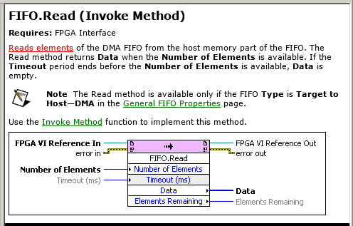
Side host I'm reading this table of DMA FIFO. The host FIFO depth is set to 1000000. I use 'Method Invoke with FIFO read' to read data from the FIFO. I read 10000 elements each time. Data output is converted to I32 and guided an extension to "decimate the 1 d array function. I use 5 indicators to represent the positions of Encoder on the host side.
And now the problem:
Position 1 Encoder shell displayed on indicator 1. But every time I close my application and run it again this position appears on the other indicator. Sometimes is the position of the Encoder 1 shown on the 1, sometimes on the indicator 5 indicator, sometimes on indicator 3... Although this position of the encoder is shown every time on the other indicator it has correct values. What I'll do as I will always receive encoder position 1 on indicator 1, position of the Encoder 2 Indicator 2...
My application has been built according to these instructions:
http://zone.NI.com/DevZone/CDA/tut/p/ID/4534
TNX,
Gregor
Normal 0 21 false false false SL X-NONE X-NONE / * Style Definitions * / table. MsoNormalTable {mso-style-name : « Navadna tabela » ; mso-tstyle-rowband-taille : 0 ; mso-tstyle-colband-taille : 0 ; mso-style-noshow:yes ; mso-style-priorité : 99 ; mso-style-qformat:yes ; mso-style-parent : » « ;" mso-rembourrage-alt : 0 cm 5.4pt cm 0 5.4pt ; mso-para-marge-haut : 0 cm ; mso-para-marge-droit : 0 cm ; mso-para-marge-bas : 10.0pt ; mso-para-marge-gauche : 0 cm ; ligne-hauteur : 115 % ; mso-pagination : widow-orphelin ; police-taille : 11.0pt ; famille de police : « Calibri », « sans-serif » ; mso-ascii-font-family : Calibri ; mso-ascii-theme-font : minor-latin ; mso-hansi-font-family : Calibri ; mso-hansi-theme-font : minor-latin ;}
Sorry Jochen, I placed the function reset at the end of my routine. L I corrected (put it on the beginning of the routine) and now it works as it is supposed to be.
Thanks a lot again!
Kind regards
Gregor
Tags: NI Hardware
Similar Questions
-
Number of DMA FIFO of items to read mismatch in the FPGA and RT
Hi all
I use myRIO, LV14 to run my application.
Request: I have to continuously acquire data via FPGA and host RT process once every 2000 samples are taken. I use DMA FIFO (size 8191) to acquire data, use timeout property in the FPGA to eliminate the buffer overflow. I had followed cRIOdevguide to implement this part. An excerpt of what I put in place is attached. All code runs in the SCTL at 50 MHz.
Question: Two or three times I met with this strange behavior, the FPGA FIFO gives continous timeout and the RT is unable to read the FIFO. The number of elements to set the property in the FPGA VI gives 0 showing that FIFO is full and no more can be written, but the RT, remaining items gives 0, so it is reading 0 (none) elements.
Solution: I put a case where I'll write to FIFO (under the code) and if the number of elements to write is different from zero. It seems to work fine, from now.
What confuses me, is that my FPGA VI said that FIFO is full (number of items to write 0 = FIFO) and gives a timeout error, but RT VI said that number of items remaining in the FIFO is 0 and therefore no data is read. No idea why this is so? My RT and FPGA VIs continues to run, but with no gains or to read data.
A few minutes after you run the code, I've seen this behavior. No idea why this happens? I try to reproduce the behavior, and will update if I meet with her again. Sorry, I can't post my code here, but I guess the code snippets to explain some extend.
Thank you
Arya
Edit: Even with the mentioned workaround solution, the problem persists, now that the FPGA written any of FIFO. And the RT VI is not able to read all the elements he sees 0 items in the FIFO. The FIFO continues to be in a State of timeout. So I guess that the problem is on the side of RT.
Why it looks like you read from the FIFO even in two different places in the same VI, at the same time? If the lower reading throws the FIFO, it will never trigger the reset, which could lead to the situation you describe, I think (it's hard to tell from a few screenshots).
Also, your logic seems too complicated. I immediately noticed that there is no reason to select the entry, the output of = 0 - simply use the 'equal to zero' output directly. On the side of FPGA, why you need check the number of items that you want to write? There's nothing wrong with writing in a FIFO that is already full. just the data won't get written.
-
Read and write in two separate FIFOs DMA on RT host
Hello
I have two parallel loops running on a host of RT on a CRio9022. There are two DMA FIFO: one of the FIFO is written for in the upper loop, another FIFO is read from the bottom loop. I've attached a screenshot of my code.
The problem I encounter is that I seem to be only able to run one of these loops - for example if I disable the first loop, I can see data through the second loop. Trying to run them in parallel because I think I've coded it means only one of the tracks-it loops is always the top loop in the code that I have attached the screenshot. Each of the FPGA VIs that run only use a FIFO so I think they should be able to run independently... I was wondering if anyone could shed some light on this?
Thank you
Hello.
You can only have a single call to the FPGA in HOST mode, the algorithm that you post, that is make two calls to the VI 'Reference of VI FPGA open', this is not allowed, this is why the program works only with one of these cycles.
Kind regards.
-
Release NiFPGA 7842 DMA FIFO after reading memory
Hello
I use the card RIO de Ni7842. I've implemented a block for the acquisition of data on my FPGA (target device) and filling a FIFO to transfer the data from the target to the host machine. I've implemented the FIFO to a size of 10 k. The number of samples that I'm gaining is 16 K on three channels simultaneously.
I read the data from the FIFO DMA implemented on a host machine with the support of the C API for the Council. I have setup the FIFO for read in three steps by launching calls to methods:
-ConfigureFIFO - configure FIFO depth
-FIFO reading - read items in a host DMA - it runs in a loop playback of 1 k datapoints at each iteration (the data type I16's not 2kb which is playing)
-Stop the FIFO
What is the memory allocated on the host DMA by calling method configureFIFO need to be released explicitly by calling ReleaseFIFO? Note that AcquireFIFO is not called here.
Please advice.
Thank you!
In my view, all memory is allocated out during the call to NiFpga_Finalize, but I was not able to find a specific documentation to confirm that.
There is a specific example of FIFO included with the C API of FPGA that my be of interest to you if you have already looked at him.
-
What would be the effect of the adjustment of the depth of DMA FIFO before every read?
I'm using a PXI-7813R FPGA board using a 3rd party API. I had a few problems during playback. I looked in their API (LabVIEW) code and realized that they were in DMA FIFO depth before each reading of the FIFO. This apparently does not cause a failure of catastrphic issues I have observed are only transitional in nature.
What kind of problems, if everything can these operations cause or will be ignored because the FIFO is already running?
Thank you...
mgerceker,
According to the help file , that should be OK to do even though I could see it being a problem if it is not set correctly before performing an operation. What kind of symptoms do you observe?
Greetings from Austin,
-
Read DMA FIFO: reads + deletes?
Just to double check:
An invoke for read DMA FIFO method: reads and deletes the oldest elements of the FPGA FIFO?
I mean that it removes after reading? Porbaly deletes.
It is not mentioned in the documentation of expelicitly:
Yes, reading is destructive (meaning that it removes the element of the FIFO).
-
Two DMA FIFO fill and asynchronous playback?
Hello
I work lately on the Labview for my system which includes the acquisition of data from two sensors in FPGA vi and communicate to RT vi, where I treat the two sensor data and subtract. I am facing a problem of synchronization. I tried 4 data points, 2 of each sensor to each 25th microsec. Here I attach a pseudo-code that is just one of my original code that shows the same problem.
When we run the code, acquire US 4 data points each 25 microsecs in the FPGA vi and storing in the fifo DMA 2.
Then, I read this in RT vi and display them.
When I have a single loop in the FPGA and RT vi. the number of elements left in the two fifo should be identical, I perceive.
But in this case, it is not. Please enlighten me why?
Concerning

Intaris is right. How work DMA FIFO is that they fill a small pad on the FPGA, and when this buffer is almost full, the data is copied (automatically and at the bottom) of a larger buffer in the memory of the host. The remaining items is the amount of data is left in the buffer of the host. The automatic copy of the FPGA to the host will happen precisely at the same time to the two FIFOs, so you will get different amounts of data in each. The total number of items (between the pads FPGA and host) should be the same, although there is no way to see that, except for read all data (until the two buffers are empty) and confirm that the total number of items of reading was the same.
-
Reading of the zeros of a DMA FIFO empty
Hello
I'm having a problem using the DMA FIFO to communicate between my real-time system and my FPGA. I use two DMA FIFO, one-way to the FPGA of the RT system and then vice versa. I can successfully get data to and from each system; However, before, after and sometimes inbetween my data, I'll get a seemingly random assortment of zeros. In the latest version of my code (which I have provided) I read the number of items stored in the DMA FIFO and read only this number to my RT system to try to get the data that I want and no zeros, but this does not work either.
I'm new to both in real-time and FPGA and so it certainly feels like I'm missing something very basic. I tried dealing with this problem by myself well and have had absolutely no success and would appreciate any help.
My equipment includes:
A Dell laptop (used as a host of the user interface)
1082 chassis
Controller of 8133 (running the LabView RT operating system)
7965R FPGA
5781 module for FPGA (not currently in use)LabView 2014 SP1
On the side of RT, you need to use a structure of the case so that you have not read of the FIFO if no data is available.
I would also like to change the flow of network to be inside of your time in a loop until the user interface capturing each data point, as it comes (connect before the loop, close after the loop and write it as the data come from the inside of the loop). This will save memory (which is VERY important in a RT system) since you don't have to set up the table.
You write only as an element in the FPGA. So any sous-suite readings should give you an array of 0 s, causing 0s back upward. You must maintain the Timed Out in the FPGA so that the data will only until to the RT when there is real data to send. Your FPGA code could be reduced to this:

-
SMU FlexRIO DMA FIFO host read the FIFO overflows broadband bandwidth/DMA issues
I'm working on an application that uses 2 modules FlexRIO, and 2 LVDS digital I/O adapters. I'm driving each of the SDC A/SDC B ports on LVDS 16-bit data at 50 MHz adapters. The FlexRIOs are expected to receive the data and write down them on four targets-to-host DMA FIFO (one per connector SDC), or two by FlexRIO. The host reads the FIFO and brings together a series of tables each FIFO output 2D. Ultimately, the individual tables (we're each a quarter of single image) will be assembled in simple images, but I haven't gotten that far yet.
The duty cycle for the data is about 80% (in other words, I'm only transmit data to the FlexRIOs 80% of the time, the rest of the time the transmitters are disabled), so the flow is about 80 Mbytes/sec/port total invasion, or 320 MB/s on the four FIFOs DMA. I find that the acquired data gaps sometimes inside that line up along the length of the material part of the DMA FIFO in FlexRIO modules. In other words, if my memory FIFO DMA are set to 65535 length, I'll see a break in the data acquired at the word of data 65536th. Data is a waveform of sight, which is essentially just a counter, so it's easy to see the break in the model. For the words of first 65535, adjoins the data, then from Word 65536 model is discontinuous and starts counting again from there, contiguously. At the beginning of the acquisition, the FIFO is erased: the beginning data read from the FIFO is always aligned correctly, so I know that the process starts at a good point.
The error is not always the case: sometimes I get continuous data through the point 65536. In addition, the error occurs independently between the four FIFO: on a particular race, a FIFO could have data of interest and some bad. Rarely, all four FIFOs have good data.
The fact that the gap of the configuration is to the point even the depth of the FIFO DMA tells me that fills the FlexRIO FIFO, the FPGA hardware without the system managing to move to read, which means that the data gets dropped during the period that the FIFO is full. Then transfer to the host comes into action, there again is the space in the FIFO, and the data is once more contiguous in FIFO memory for a large amount of data (I have not yet tried to locate a second gap in the data of a single acquisition). It seems therefore that the host doesn't have enough bandwidth between the FlexRIOs and the host of RAM to prevent the filling FIFO, or comes along some software process on the host that is temporarily stop the ability to instantly transfer.
Are at - it a specification for the SMU flow system that would indicate that we are trying to use too much bandwidth? Or are there priority controls on DMA FIFO that would allow us to raise the priority of the FIFO transfers as they are guaranteed to go in preference to other system tasks?
System Specs:
SMU-1075 chassis
SMU-8135 CPU
2 SMU-7962R FlexRIO modules
2 digital i/o modules of NOR-6585
LabView 2012 32-bit SP1 version 12.0.1
A suggestion of an applications engineer of NOR and some experimentation has solved the problem. It turns out that I was calling the method FIFO of DMA stop just before the outbreak of the transmission of the data via a control for the FPGA FPGA VI. I did this in order to clear the FIFO before you begin data acquisition, but I didn't know that this method disables also transfer data between the memory FlexRIO and host. Following this call, I trigger the FPGA code to start filling its FIFO and then begin reading. Calling the Read of FIFO of DMA apparently light up the transfer back, but it seems that the host VI has been randomly slow down enough to move to the bed such as filling the side FlexRIO FIFO and dat would be lost. I changed the host VI to insert a FIFO method call start before the trigger for the FPGA signal, and the problem is now gone.
-
simple DMA FIFO reading two analog channels
Hello
I have a question on a method of data transfer between two analog inputs for a simple DMA FIFO in FPGA. The code is described here: http://decibel.ni.com/content/docs/DOC-6303. If I use this method, and I got out in a graph of my host VI, the calendar in the graph reflects the same schedule as the signals that have been entered? Or will they be phase shift between two signals?
Thank you
Grant
Grant:
Because it is not all information of timing with the signals in the FIFO, there will be no lag phase on the chart.
Hope that helps. I would like to know if I forgot something, or who does not explain very well.
Thank you!
-
Hi guys!
I am writing here after many days of attempts without success...
My request is 'simple', send data from the Panel of Labview RT within a DMA FIFO target host. Then the FPGA core receives data and imported through a knot of VHDL processes, and then after the data is pointing to the Labview RT through a target to host DMA FIFO.
I tested my node VHDL simulation mode in Labview FPGA where data sent by a target scope THAT FIFO and just work fine.
But when I try to run the node VHDL in the real target with data from the RT by DMA FIFO basis, it won't. I already do some checks:
-Data are properly sent through the host target DMA FIFO;
-The data are correctly received in the FPGA base;
-The data are correctly sent to the node VHDL;
-Result of the node VHDL are correctly sent to the heart of the RT through the target to host DMA FIFO;
-Result are correcly received in the heart of the RT, , but the result is false and absurd. But I have proof that my node is semanticly correct with my mock test
So my question: are there reasons to see my work VHDL nice knot in simulation mode and not in mode real target with data from the base RT by DMA FIFO taking into account data Transfer between DMA FIFO work well in both sides? Is there some sample available with data send RT FPGA-based via DMA and data processing with a knot of VHDL and returned to the RT kernel to inspire me?
I can't post my screw here because I work for a company, I use a MyRIO with Labview FPGA 2014 target.
Thank you guys! I am available for some details on my implementations.
Afghow.
Hey!
Thank you for your answer but I solved my problem. Indeed, at first, I tried to make a knot of Combinatorics (without clock) pure, but the problem seemed to come from that.
I modified my node in order to incorporate a clock, according to the prescriptions of this white paper: http://zone.ni.com/reference/en-XX/help/371599K-01/lvfpgaconcepts/ipin_prepare_ip/ . And now, every thing seems to work well.
The question remains why the combinatorial node has worked in simulation mode en not in the actual target?...
But for people with the same problem, I suggest add them a CLK and check an edge of entry with rising_edge (CLK) and if it does not, add an input signal to check if the input signals are valid or not.
Afghow.
-
Transmission of data to the host of RT to the FPGA via DMA FIFO
Hello
I try to write data from a host of RT on target FPGA using DMA FIFO and then process these data and read then return of the FPGA target to the host of the CR through an another DMA FIFO. I'm working on the NI SMU chassis 1062 q, with the built-in NI SMU-8130 RT controller and target FPGA NI SMU-7965R.
The problem I face is that I want to send three different tables, two of the same size and the third with different size, and I need one more small to be sent first to the FPGA. I tried to use encode dish with two executives in the FPGA VI. In the first image, I read and write the first table in a while loop which is finite (that is, a finite number of iterations). The second frame contains the process of reading and writing the second two tables (of the same size) in a while loop that can be finite or infinite (depending on a control). The problem is that it does not work. 2 arrays are displayed on the front panel of the RT VI host and works well, however, the table that should have been read in the first sequence does not appear on the front panel of the RT VI host. It is not sensible because if it is not passed from the host to the fpga and vice versa then the second image should not have been executed. Note that I'm wiring (-1) for the time-out period to block the while loop iterations until the passage of each item is completed. So the first while loop has only 3 iterations. Could someone help me undersdtand why this happens and how to fix this?
I enclose a picture of the host and the fpga vi.
Thank you.
If you vote for my idea here and it is implemented, you can even omit the loop FOR fully.

(I also propose the RE / IM divided inside the loop FOR and perform operations on complex table before the loop the transpose and reshape .) In this way, you only need one instance of these operations. You might even save some unnecessary allocations table in this way)
-
How is managed using DMA FIFO (target host) host matrix
Hi people,
I'm trying to pass an array of values of the host to the FPGA using DMA FIFO. Let's say 20000 items in the table. My FIFO host side can contain only 16000 items or almost. The data will be written element by element regardless of the size of the table or do I need to partition the table in small paintings before writing the FIFO method? Let's say that I write for the FIFO with berries small, 1000-element. The FIFO will read 1 element both of the side FPGA so the stream is blocked until I have at least 1000 free items on the FIFO method write, how he writes every 1000 the next setpoint at the same time? Or target values will be written permanently as soon as the individual elements are erased by the number of available items to write?
Hi Nathan,
Sorry for the late update, but I just thought that I should follow. I followed your advice and try it tested just for me (I probably should I have done it before posting). Turns out that the data table will write even if there is not enough empty elements to contain the table in its entirety. However, it always crashes until enough information is read and erased from memory on the side FPGA for the whole table. So if it's data that are constantly being played, it's always better transmitting data through in the form of smaller tables if you do not want to increase the amount of memory FIFO host OCCUPIES on your system. However, if you can afford the memory while you mentioned, you can always increase the depth of the FIFO on the host side. As I understand it, try to write more big berries to a host to target FIFO buffer does not diminish overhead costs (as is the case with a target to host FIFO) as it still passes an element at a time to the FIFO of FPGA-side without worrying.
Thanks again for your help.
Kind regards
John has
-
Hello
Let me describe the problem:
I have a FlexRIO (5751 + 7961) in a PXI system with a controller SMU - 8133 RT. (LabView 2011 SP1)
The 5751 writes each data of 100µs in a FIFO DMA and the RT controller he reads every 100µs.
But after reading in the RT controller several spikes occur as indicated on the attached figure.
The FPGA is also attached.
I tried a lot of things, I really think that the tips come from the DMA FIFO.
Can someone help me?
Your
Hello
Finally, we have found a solution!
I don't know why, but the problem was the FPGA VI. We did as it is done in the example of NI5751 oscilloscope with a state machine.
Maybe the IO need the Module e/s 0 clock to work.
Thanks in any case!
-
How to choose the maximum number of items for DMA FIFO to the R series FPGA
Greetings!
I'm working on a project with card PCIe-7842R-R series FPGA of NOR. I use to achieve the fast data transfer target-to-host DMA FIFO. And to minimize overhead costs, I would make the size of the FIFO as large as possible. According to the manual, 7842R a 1728 KB (216KO) integrated block of RAM, 108 000 I16 FIFOs items available in theory (1 728 000 / 16). However the FPGA had compilation error when I asked this amount of items. I checked the manual and searched online but could not find the reason. Can someone please explain? And in general, what is the maximum size of the FIFO given the size of the block of RAM?
Thank you!
Hey iron_curtain,
You are right that the movement of large blocks of data can lead to a more efficient use of the bus, but it certainly isn't the most important factor here. Assuming of course that the FIFO on the FPGA is large enough to avoid overflowing, I expect the dominant factor to the size of reading on the host. In general, larger and reads as follows on the host drive to improve throughput, up to the speed of the bus. This is because as FIFO. Read is a relatively expensive operation software, so it is advantageous to fewer calls for the same amount of data.
Note that your call to the FIFO. Read the largest host buffer should be. Depending on your application, you may be several times larger than the size of reading. You can set the size of the buffer with the FIFO. Configure the node.
http://zone.NI.com/reference/en-XX/help/371599H-01/lvfpgaconcepts/fpga_dma_how_it_works/ explains the different buffers involved. It is important to note that the DMA engine moves data asynchronously read/write on the host nodes and FPGAs.
Let me know if you have any questions about all of this.
Sebastian
Maybe you are looking for
-
HP 8600 Series OfficeJet 2nd second paper tray unit Pro Premium OEM will be that this made a 8620
-
HP G60-535DX Notebook PC CDDVDW TS-L633M ATA Device
I have a HP G60-535DX laptop and Norton has found a corrupt driver: CDDVDW TS - L633M ATA Device. I uninstalled and tried to find an answer here on HP.COM, but fails. How can I get a new driver?
-
Photos don't preview - only show icon
HelloWhen I try and view my photos in the folder, it will not preview the photos - it shows only the icon picture for them. I know that's not standard, as pc of my parents with the same snippets of software! Any suggestions?See you soon,.Cassen
-
Lack of driver for ethernet controller (manufacturer: Realtek)
I bought a hp 3330 pro MT PC with linux OS preinstalled. Just installed Winows 7 Home Basic (32 bit) Edition. The ethernet controller driver is missing. I tried to download a driver to install hp under my serial number of the product (sgh213t214). No
-
Output HDMI not working do not after Windows 8.1 update
I use an envy TouchSmart 15 and I just launched an update of Windows based on the automatic system update 8.1 (he ran 5 updates). Before the update, I've used a 27 "monitor in the main screen, and it was connected via the HDMI port. Just after the u