Recording signal
Hello
I'm new with LabVIEW. I need it for my project. I use the interface USB (k8055) card. I know it's not good to use it, but I have to use.
I don't have counter on this forum. I need to record a signal and transferee it to a file where I can look at the time at which the pulse is generated.
I have a sensor this sensor pulse send (k8055) USB interface card. I want to measure the time between each pulse and the duration of each pulse.
I have of course a timer. I found the timer on the forum, but I does not work with what I'm building.
As I mention, I'm new in LabVIEW. I use LabVIEW 2010
Hello Nadjil,
Thanks for the additional information!
Below some comments from me:
(1) in the context of acquisition VI now read you the data and save them in a file (in collaboration with "time information")
Time you get currently comes from the VI of number of cycles and won't give you information on when the DLL was called.
This can give you indeed information on when the acquisition is made, but it will never quite add up.
You might be able to make it a little more accurate with both the call to the function 'ReadAllAnalog' of the dll and the call of the VI of number of cycles in the same flat Structure of the sequence. This way you could maybe get a little more specific information when the DLL is called.
However, it still won't be exactly at the time the effective acquisition is made on the Board from velleman.
(2) when you talk about "the counter" what should I say exactly?
Are you talking about the data produced by the number of cycles VI?
Essentially the information you can get from this are the relative difference between different calls to the function 'ReadAllAnalog' of the dll.
Simply subtract the first 'number of cycles' of the entire procedure ones.
(3) it is still is not clear to me why you need to reopen the connection to your device in each iteration of your loop.
(4) it is also not not clear to me why put you your waiting until the next multiple ms VI in a loop with 1 iteration for?
The reason for adding in this loop is also not clear to me. It's not be used anywhere, so it can be deleted.
Tags: NI Hardware
Similar Questions
-
HDR5010KB-digital recorder - signal does not always come through the use of HDMI
Hello
I bought the product above in October. Since then, I have had intermittent problems. When switching on the channel AV on my TV (a Panasonic TX-P42S20B) signal is not always crossed when you use the HDMI channel (I also connected via a SCART, and who works so always seems to be a problem HDMI.) It is particularly obvious when the recorder has been used for a while (be it for recording or playback.) It is not overheating (or if this is the case, not to the degree I get a warning message) and turn off the power to the electric network seems to correct the problem, but it's a pain.
I tried to change the hdmi cable, as well as to try different channels AV on my TV and it did not help. Is this a common problem or make me a defective unit?
Any suggestion would be appreciated
Have you noticed the same problem using other devices connected to your TV (using the same cable)?
-
Digital synchro recording signal using PFI0/PFI1
Hello
I try to sync data between an instrument NOR cDAQ-9188XT acquisition and a 3rd party.
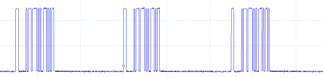
The instrument of 3rd party kicks out a digital synchronization signal which consists of a short pulse whenever it samples followed by a series of pulses coding a 32-bit integer (see image - signal synchronization for 3 bags). This integer is the serial number recorded with each packet of data. Samples of instrument to a pace of 2 kHz, so the pulse + whole occurs every 0.5 ms and by my rough calculation, each bit of the integer lasts 5 µs.
The cDAQ-9188XT will record a series of analog channels by using LabVIEW, and I wish to record this signal to synchronize with the analog channels, so I can sync the two sets of data in post processing. There is no spare slots in the cDAQ so I can't use a digital I/o module and I believe that the frequency of sampling of my analog channels will be too weak to pick up the signal from sync.
The cDAQ-9188XT has two BNC connectors on the frame that correspond to lines PFI0/PFI1, I would like to know if it is possible to use a PFI line to record this signal of sync?
See you soon.
Pat.
Think about it once again, if you're happy with the post-processing of the data, then you can get in with the straightforward acquisition code (maybe start with an example of the semi buffering period ). This will give you a picture of the down time of the signal that then you need to decode in the 32-bit number.
Best regards
-
Incorrect behavior when using the sliders on a signal enlarged
I started recently by using sliders to determine specific values in a recorded signal.
Problem is when I use the Zoom tool (the magnifying glass under the time scale icon inside) to zoom in on a specific peak dysfunction of sliders. When you take a slider handle and drag the intersection of cursor is no longer follows the track of the signal in the graph.
To recreate:
- Log data with Signal Express seconds. I always pass the signal by the amplitude and levels step to display the signal as a graphic of the scope.
- Right-click on the graph and select visible items > sliders to add the sliders to the chart
- Use the handles to slide to move the cursor cross along the signal.
- Click the magnifying glass in the time scale, and then select the Zoom (top left of the box that is displayed)
- Click and drag on the chart to zoom in on a signal peak.
- Now use the grab handle sliders intersect on the zoomed pic in.
- Cursors follow the path of the signal.
I'm pretty confident that it's recreateable, because the same behavior exists on both machines in the lab as well as the software in beta 2011 at my office.
Rory,
Thank you for your patience during the attempt to isolate this problem. I'm glad that you could see up to a kind of stange behavior.
You describe exactly what I see on my end. If you zoom in far enough the sliders 'think' it follows the signal when in fact it's a ghost left by an already enlarged resolution signal.
The solution is to change the graphic for graphic band momentarily while I use the sliders, and then back again to view the actual data.
This isn't really a drawback, but I'm happy that we can document as a bug.
Thank you!
-
How to continually take and record waveforms with neither 5102
a machine generates waves sinusoidal time randomly. I want to permanently take and record waveforms in 10s by NI 5102.
How to do?
Thank you very much!!
Thanks for the review! but this isn't a supported NEITHER.
I record signals by this method.
and the promble news is that different sampling frequency, the different wavelength. for example, when I put the sampling frequency is 4 k, the wavelength is 12 seconds if the sampling frequency is 10 k, the wavelength is 8 seconds the signal under test 1 k, the time constant is 10000.
now, I save waveform to 10 sec. What is the best relationship between sampling frequency and the time constant?
-
Accelerometer (voltage) of the signals using the module NI6361 (PXI)
Hi guys,.
I posted this question once again, but I still have problems with the acquisition of data. I'm acquiring a voltage signal by using an accelerometer module and single voltage NI6361. I would like to set up the accelerometer to measure a range of signal between + / 5000g.
The accelerometer sensitivity = 0,516 mV/g where
1 g = 0,000516 Volts or
1938-g = 1 Volt or
5000 g = 2.58 Volts
-J' left the signal conditioning with +/-10 Volts (despite the fact that there is another option value +/-5 Volts as well)-please see attached pdf
-I entered the units sensitivity to g
-J' put labview to measure a signal between +/-10 Volts to the single a complete axis accelerometer.
-An oscilloscope was related to the card, and she won the same vertices with the LabVIEW. -Please see attached pdf
-By knocking gently on the accelerometer, the recorded signal was 400 mV = 0.4 V where he gives an acceleration of 775g.
-L' accelerometer is also fixed on the ball for a shock test fell from a distance of 50 mm. The recorded acceleration was 4000g which is quite high for such a small distance. I expect an acceleration of about 200g of 2 to 4 meters according to some documents as well.
Can you please give me any help on the way in which the parameters are specified correctly between the accelerometer and the coupler? I'd appreciate it highly if you can correct me if anything of the above statement is false. I have attached a PDF for your convenience.
Kind regards
Since gain is the scale factor for tension, you must divide your results by the gain.
g = voltage / (sensitivity * win)
-
Looping/cycling through frequencies with the signal to create VI
Hello
I am trying to operate a PZT with a given signal (of a formula) and to save the output of the sensors. I use a PXI of NI 5421 to generate the signal and an NI PXI 5105 to record signals. I made the attached code that works well, however, I'd like to be able to the frequency and the number of samples (the number of samples is function of frequency) in the VI of signal to create loop so that I can scan a range of frequencies. Could you please help me. I can't find a way to control the frequency outside the edit in the Properties window.
Thank you
Casey
Sanjay-thank you
I just thought of it. I Redid the vi and when I ran an error that said come the input signal must be an integer value to a multiple of 4. I made a few simple changes to make and after that everything worked as expected. I guess that the entrance of waveform looked ok but not get operated by material, unless it is a multiple of 4.
Thanks for your help,
Casey
-
Hi all
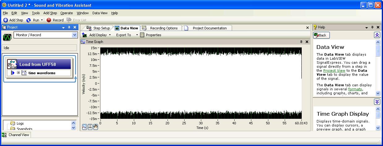
I recorded a minute of a machine with the audio wizard and vibration noise. This temporal measure was recorded in a PDM file. I want to export TDMS signal to a file of the UFF. How can I do this?
Thank you!
Best regards
Aitor Aramburu
The steps in the function menu load/save of the signals in both types of work areas. Use the area of work/record of monitor so that your calendar is not dependent on any file selected journal. After the addition of step: load from UFF58, select the file you want to view the process, run the project (once), and then drag the step to display output.
You can also process the data with the other steps by right-clicking the «time of the waveforms» signal and select send to. This will show you a range of steps that operate on the waves of time. For vibration of machine data, the following steps may make sense:
Analysis > time domain measures > level of vibrations
Analysis > measures of the frequency domain >...
Analysis > the field order measures >... (especially if one of the recorded signals is a tachometer signal or has a strong component related to orders which can be used as a speed reference)
I hope this helps.
-
6009 outputs digital and analog input synchronization
Hello
I work in a program NI 6009. I want to leds by car with outputs digital NI 6009. For example, leads first will be on until what 200 micro seconds then second led will be on up to 200 micro seconds, and then first of all led will be on up to 200 micro seconds. I'll take led with photodedector signals and connect analog output photodedector input NI 6009. I want to synchronize the outputs digital and analog input and separate the first and second led signals the analog input for NI 6009 channel. How can you do with NI 6009? Please ADV
You can not do with the USB-6009 case. Its outputs digital are software with a maximum speed of slightly more than 100 samples per second. The outputs can produce 200 microsecond pulses and cannot be synchronized with the analog input.
You need a device with outputs digital hardware timed or counters that can produce a pulse outputs.
You can synchronize a bit digital output and analog input recording signal on an additional channel to HAVE. Will allow you to see the photodetector and LED the drive with the same schedule and such resolution as described by the sampling rate I. The maximum sampling frequency of AI on the USB-6009 case is 48 kHz that is shared by all channels. If you have two lights to led and photodetector two signals maximum sampling rate would be 48 kHz/4 = 6 kHz which is barely fast enough for your 200 US signals. For more than 4 channels, it won't be fast enough.
I suggest a simple oscillator circuit building and use it to clock a flip flop. This will give you alternating signals to drive the LEDs. You can use a line to reset the flip flop to give you control without the need for high speed.
Lynn
-
Design practice nor 6008 USB DAQ
Hello
I have a few question, I'd like to introduce. I need some sort of indication on how to better perform a timed cycle of acquisition driven by WSF.
I'll send my VI (conceptual, not one currently working one) and ask for explanations.
The goalI need to acquire a battery voltage. Load current consumption is driven by a couple of transistor. I drive the hollow transistors two digital i/o for USB data acquisition.
Because I need to have a power for a given time cycle, I need to have some sort of time control on the output.
So I wrote a simple state machine whose States are updated when a timer reaches zero. Each State has its own queue time.
Moreover, I differentiate between acquisition and control operations using two all in cycles.
First question: is this a correct way to a timed WSF of construction?and now:
The problem (s):
I need to connect and establish a correlation between the input line for the internal of the fsm States. So I madesome digital indicator on the face before of the VI and created a local variable (I know that local variables are BAD, but I had no other idea everything) to pass values for some time to the other.
I also want to select State sequent of the FMS based on the input value, I get a channel. I can stil use a local variable?
Are the two related tasks?
Second question: are local variables, something that I can use for this task?
Last but not least: I need to filter on the values.
In this vi I perform a filtering operation and then I get the I use for control of local variables.will be this filtering desync the two cycles while? will I run out of control before running the filtering?
The same question is valid for the purposes of registration: the unfiltered data record, I guess is unnecessary. But based on this 'architecture' I know the country reports and the recorded signals are out of sync (as happens in many game data acquired with this vi).
Is this a problem of logging (perhaps given by different buffers for data acquisition and internal State or something similar) or the whole WSF will be out of sync, then all acquired data is more useful because it is out of sync?Any advice would be much appreciated.
Best regards
Luca.
Luca,
Question 1: This is a reasonable start but need some things to make it a good WSF. There is no waiting or delay in the loop so it will run as fast as possible. U.S.-6008 outputs digital software timed so that the DAQ Assistant can take a long time, but the amount of time is unknown and not necessarily consistent from iteration to iteration. Since the DAQ Assistant Analog Input in the other races of loop to<= 10="" iterations="" per="" second,="" a="" wait="" of="" 100="" ms="" in="" the="" fsm="" loop="" seems="" like="" a="" good="" starting="" point.="" waiting="" 3000="" ms="" is="" not="" a="" good="" idea="" because="" the="" loop="" becomes="" unresponsive="" to="" the="" stop="" button="" for="" long="">
Do you need to write on the lines on each iteration, even when the data has not changed? Add a write state that is called only when the data changes.
The DAQ Assistant has a Stop input and an output of Stopped. When you are ready to stop the loop, the stop signal must be wired to these inputs so that the DAQ Assistant can delete tasks. The output of the order can be connected to a Terminal to stop the loop.
Problem (s):
It seems that you want to link the two loops. Local variables are usually a bad way to do it. The best way is to use queues. A queue can send the current state of the file loop. (More comments later if that's really what you need). Another line can send data, or better, the commands, the loop of the file to the loop.
I think you want digital output values rather than the State. Especially if you add a State writing as I suggested above, the current state will not always represent the condition of the power of your test. To make this work with the additional state Boolean matrix must be moved from one iteration to another via a shift register.
It seems that you have at least two controls to be sent from the loop of the file to the loop. One is the stop command. The other went to the higher power level control. You should probably have a command to set off power level which can be used if the battery voltage becomes too low and before stopping. How your program is currently configured, the last level of power will continue as long as the power of the computer is on and the USB-6008 is always plugged. The cessation program does NOT reset the lines.
When you use anti-parallel to the queues, you must be careful on the definition of wait times and the timed out case management.
The benefits of the queues are that it is easy to ensure synchronization at the level you need, the data can be stored according to the needs, and there are good examples. It also avoids the possibilities of race conditions, often introduced by local variables. This program could be based on a variation of the design producer/consumer model.
Filter questions: any filter introduces a time delay. In your case when you filter 100 samples 10 times per second, it is likely that the filter will do well until the next data set has arrived. The delay of the filter is not affecting your synchronization. The above lines will solve problems. Since you are looking at time of cycle seconds and the minimum interval on the order of 100 ms, the exact chronology (to tens of milliseconds level) is probably not too important.
The real question about filtering boils down to this: does the control work better if the signal is filtered?
- - - - -
I'd probably all this a little differently. Given the slow speeds and the small amount of data, a simple loop with an improved state machine is all that is needed. Get rid of the DAQ Assistant and learn how to use DAQmx screws. States could include: Init THE Init, Init File, Idle, read, write, DO, Analyze, filter, adjust the power, wait, Save, close file, DO, AI Shutdown Shutdown, error and exit. No variables. No indicator fake just to allow the creation of local variables. Very little code outside the structure State case. None of the queues.
Lynn
-
I connected a signal Signal Express. The recorded signal was acquired of sound spectrum of a NI DAQ system. I want to select only part of the spectrum, do a mean quadratic value and then create a snapshot of that part of the sound spectrum medium to export to Excel. This is the step I did:
- Add step--> analysis-->--> measures areas of frequency power spectrum.
- In the average label--> with an average of Mode--> mean quadratic value.
- In the playback Options label--> for example: Start time-> 12 000 stop time: 16 700
- Scan of the spectrum to the data view
My question is: what do I have to pulse 'play' buttons to make an average of these 4 700 seconds, then create and snapshot to export to Excel? If I push "play" it does not and the average of this time interval, the signal continues to scroll. Y at - it any othe for this option?
Thank you
Aitor Aramburu
The following equation can help you understand your FFT resolution.

Delta-f - resolution FFT
FS - sampling freq
N - length of FFT
So if you re - sample at the same sampling freq relative to the length of the FFT, you get the same resolution. Note that you must always respect the theorem of niquest to maintain the validity of the results.
More of the subject can be found here
-
I want to increase up to 32 GB of system RAM. This will require Windows 10? I currently have Windows 7 Home Premium.
This Kingston RAM will work:
Size of memory 8 GB
Memory DDR3 SDRAM technology
1600 MHz memory speed
Standard DDR3-1600/PC3-12800 memory
ECC error checking
The recorded signal processing
Also, I want to be able to run 2-28 "monitors UHD or almost full resolution. What graphics card would recommend someone? I understand that the card must have at least a DisplayPort.
HP initially, as an option, the GeForce 680 GPU GTX. So I guess it should work.
My system has the processor i7-3770 @ 3.4 GHz
Thanks for help with any known RAM/cards that work on this system. And extra thanks for suggestions on the question if I need to upgrade to Windows 10 do all work as well as all changes to the Bios can do.
Big_Dave,
I want to thank you for all your help and suggestions. I already bought Windows 7 Pro.
I've set up CPU - Z.
I will contact HP sales for upgrades of memory for my system.
I went to the site of Kingston memory tools. He suggested that using 4 GB modules since it is probably set up for a maximum of 16 GB with Windows 7 Home Premium. I need to work on that.
And what a great suggestion on the graphics card. It has 2 DisplayPorts!
You are the best.
Thanks and I'll let you know how it works.
Gary
-
Hello
I wrote a simple VI to make playback of audio files and to record signals. It seems to do what I want (although I appreciate the General comments on good programming habits). The biggest problem I have is that the binary file, that is to save too much size. A few seconds registration gives a few megabytes of data. Although I can open binary file in matlab and analyze the data very well, the large file size does not look good.
Anyone know why this is the case? I tried to save the data into something else of the double rooms, but he always gives large file sizes. Played around with the byte order too without great success. Any help is appreciated (LV 2009 attached file).
Thank you.
FA
If your data acquisition unit is 16 bits or less, just to store data like I16. you store data more DBL and this is the number of pr of 8 bytes. It is perfectly feasible in I16 as wav files. However (in Labview at least) wav files is not a tablet. If the file size will be much larger than the MP3 files which is a compressed file format.
-
Switch between the graph and the table as in the DAQ Assistant
I was wondering if it is possible or if anyone has any success making a user interface, such as the DAQ Assistant, where you can switch between a graphical output or an array of the recorded signals. I would like to have this feature in my code .VI. From now on, I'm just a waveform graph in my front panel. I'd love to be able to alternate between this waverform table and a table of output values. I have attached a few screenshots to explain what I mean.
Hello
Personally, I like the TAB ideas that have been validated, but you can also use property nodes and the visible value.
Good luck.
Steven
-
sound and Vibration Assistant. Speaker output
I am new to the sound and Vibration Assistant and he had to get monitored sound of a surfboard 4722 the speaker to computers. I can capture data and display it, but I want, but can't seem to find a way to get the sound to the speakers. Thanks for any help
Hi Mike.
Unfortunately, the Sound and Vibration Assistant doesn't have a built-in way to route your signal input to your speakers.
However, if you have LabVIEW, you can add a step to run a LabVIEW VI that generates output a file from your computer speakers (or external speakers). You must write a LabVIEW program that either acquires a signal or load a file of recorded signal, then this signal to your speakers. "You will most likely use the Play Waveform Express VI of the Express" exit pallet on the block diagram. "After you wrote this program, you need to add a step in the sound and Vibration Assistant using the Add a step" run a LabVIEW VI.
I hope this helps. Good luck with your application!
Maybe you are looking for
-
Option of the TDC - WIS (FILE) at startup
Model portable spectrum XT 15-4013cl Ultrabook, product no. C2M72UA - provided with Windows 8, updated to 8.1. The operating system would not little matter what I tried with 0xc0000034 error code, so I did a full restore to the condition as new usin
-
Meet the error code during upgrade to Windows 10 Windows 7
I encounter an error code: 0xc1900204 during the upgrade of Windows Windows 7 10. Anyone has idea what the code refers to, and how it can be fixed?
-
I want to remove an email address of my sign in
Any suggestions on how to remove an e-mail address of the login page? A friend used my computer and now I want to you want to remove this e-mail address.
-
BlackBerry Smartphones 8830 calendar Synch issue/Vista 2007/Office Mgr v5.0.1
I use Vista 2007; I have 5 accounts of e-mail on my 8830 - none are related to Microsoft Outlook. Somehow, my calendar on Outlook using an e-mail address that is not the default configuration on the 8830 synch (I had to e-mail to the default list on
-
How much do pay update creative cloud?
My creative cloud being exhausted, how much must I pay (Canadian money) to update?How much should I pay for Photoshop CS6?