Reduce read/write SPI function 5bits.
Hello
I got a project to develop an SPI interface with 7 bits of address with a bit in mode (R/W), but records of test being only 5 bits wide. Is there a way to get the Subvi interface USB - 8451 SPI limit the number of bits in the data stream? Or you can release the chip, select so that only 5 bits are sent. If anyone has had some experience with it please let me know if this is possible.
Gary Tyrna
ggaryt wrote:
Thank you for your answer to my question. Unfortunately I can not bit-bang because of the operating speed of 50 MHz.
Well, it's just a little one important fact.
NOR has only 1 SPI devices. I'm not aware of the third SPI devices that can operate at this speed, not to mention control the number of clocks.
I know not all this with the FPGA, but the basis for the LabVIEW FPGA Module specification is a 40 MHz loop rates. You may need to look at some digital devices at high speed that sells some OR. My suggestion is to contact your local sales representative OR.
Tags: NI Software
Similar Questions
-
In the target FPGA read/write control function?
Hi people,
I learn a lot from the sample project FPGA, including how you can easily retrieve and set controls and indicators in an FPGA using the read/write control function running in an RT target.
However, I can't find a way to do something similar in a FPGA target. I've been down this road before - that is, trying to move the data in/out a looping VI FPGA (void) to a (parent) FPGA VI - where my memory points to reach what I needed use.
So I was happy to see the palette FPGA enabled me to drop the control functions to read/write on a FPGA vi target. But alas there where tons of errors (not compatible son for target, etc.) and I guess now it's not possible.
So, just to be sure, I'm not missing something, is there something like control functions to read/write to use in an FPGA for read/write in an another FPGA (looped)?
In addition, why would I be able to read/write on a FPGA vi control functions if they are not supported? (Sorry for the n00b question)
Thank you
Steve
maherhome wrote:
You're right that I don't have this knot in my palette. However, I also do not seem to have a Refnum Occurrence in the palette is in the FPGA (see below), but I need to synchronize several loops of FPGA and added research using the textfield in the VI editor (and if compiles and runs). So 6 months to Labview and I'm fuzzy on how the palette is restricted
I don't know what you're trying to prove here. There is no control of refnum in search in your image. Occurrences are available in FPGA, and for control of refnum for one you just right click on a function of the instance and create a control. If you can create a valid thread of a certain type of data, then you can create a control or the indicator for it, regardless of the question to know if this type of control or indicator appears in the palettes. However, the functions that you can use in the block diagram are limited by what is available in the palettes.
maherhome wrote:
Regarding orders read/write for the FPGA/lights, I'm surprised that the infrastructure developed to allow read/write between RT and FPGA has not mobilized to allow read/write between FPGA and FPGA. The elements of memory function, but they are less convenient.
You may have noticed that you cannot compile the individual parts of an FPGA VI and combine them later; This is because when you compile an FPGA VI, all its subVIs are essentially merged to create a single block diagram (with additional logic if one not reentrant Subvi is used in multiple locations, this is why it is not recommended on FPGA). The subVIs no longer exist in the FPGA compiled; reading and writing a control on them would make no sense. If you want similar behavior, use global variables - but understand that global variables store values in FPGA logic resources. Using the elements of memory (or FIFO, which can also store in memory) leaves more fabric available FPGA logic by storing data in resources specially designed for this purpose.
-
NEITHER USB-8452 - reach the maximum write SPI speed
Hello
I have a USB-8452 with the latest version of the software installed (2.1.2). The host computer is a Core i7. I am trying to achieve the maximum SPI write speed with the camera possible. I tried the basic block read/write SPI, SPI Scripting blocks and SPINNAKER streaming, but the first two have large delays between CS falling and the data being written (with so that delays in loop), and the last seems to be useful only for read operations.
Can someone tell me if there is a way of a) reduce the time of installation for basic SPI / SPI Scripting or b) writing different values in a single stream of SPI? Thanks in advance for any help on this issue, even if it's just confirmation that yes they is hard limits that cannot be overcome with the LabVIEW 8452 interface at this time.
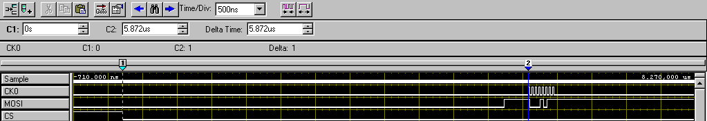
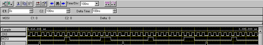
Here's the best I can do right now, as shown in my logic analyzer. Change of the SPI clock speed does not affect installation time and delays that are primary and secondary bottlenecks:
SPI read/write database-
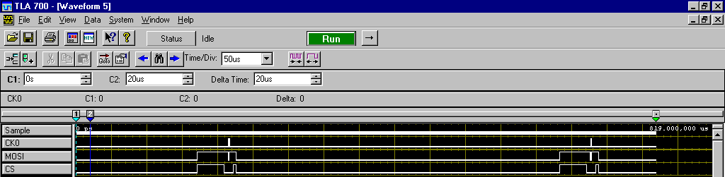
Program: Basic Configuration followed by read/write of SPI block itself in a while loop
Main bottleneck: ~ 450 delay us into iterations of the loop (see Figure 2)
Secondary bottleneck: ~ 6 us delay between falling edge of CS and the first synchronization signal (see Figure 1)
Capture 1 - delay highlighting between CS falling and first SCLK pulse
2 delay highlighting between all iterations of the loop of capture
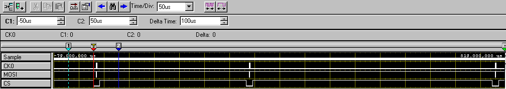
Scripts of SPI-
Program: Followed two Script blocks Basic Configuration run in a while loop (to check the two block to block and delay loop iteration)Main bottleneck: ~ 450 delay us into iterations of the loop (see Figure 3, space between the second and third images captured)
Secondary bottleneck: ~ 250 us delay between blocks of Script run consecutive (see Figure 3, space between the first and second captured images)
Capture 3 - highlighting delays consecutive run the Script and delays between while the loop iteration
SPI in Streaming- It's the closest to achieve a fast writing speed, but unfortunately, it seems to be only useful for read operations (e.g., ADC), do not write.
Program: Configuration of the base stream followed by start of the flow block
Main bottleneck: impossible to write something else than the data value unique property "wave 1-> MOSI data." I can write a byte array to this property, but it will simply put all these bytes in an image and repeat this framework (see Figure 4) rather than go through each value.
4 - two bytes sent repeatedly using SPI capture stream. Delay of CS is finally good, but no possibility to change the MOSI image to image data.
Hi JBender1,
This show looks like what we would expect for a 8452.
If you need higher performance, I encourage you to watch using a card R or FlexRIO FPGA series for your implementation.
-
Hello
I am writing a VI to control PWM with a microcontroller via a serial port. I wrote a simple code for the microcontroller that allows me to set the ratio of duty cycle on a scale of 0-65535. It works very well with Termite of Compuphase (RS-232 plug); The microcontroller invited me to an entry, expected that I would one, updates and expected another entry when I decided to send him. Now, I'm trying to get the same functionality on a LabVIEW vi but hit a snag.
When I tried to send my orders with a series read base and an example of writing, everything worked fine. I could see the prompt entry, write an entry and if I was quick enough, check out the update message. Even when I was not fast enough, I was able to check the update by monitoring the PWM pin with a Logic Analyzer. The problem with the basic example, however, is that I need to update the report to aura cyclical ratio, so I went for an example of reading continues writing. The problem I've met; is that I have to switch between reading and writing to make it work. When I do that, either I don't hold write it down long enough and nothing happens, or I get several updates when I switch to reading. Some of these updates don't even match and produce updates to defective upgrades for example; 16000 16000, 16000, 16000, 6000, 600, 60, 16000, 1600, 60, 0, 0, 0, 16000, 60, 0, 0 etc.
I tried which allows characters of endpoint in the hope that the writing would end at the end and go to reading where he would receive a termination character and wait for me allow writing once again, but nothing helped. I still have to alternate between the two and either get no response on reading several updates of variable accuracy. I tried to remove her allows read/write and their structures of matter in the hope that the loop flow, associated with the characters of endpoint would the case, but then the updates don't register at all. The funny thing is I did a VI like this before with an Arduino and that there not even no need to switch between writing and reading (I'm now using a Board of Freescale FRDM).
I was also the frequency of timeout errors; Error-1073807339 at VISA Read, reason Possible: VISA Hex 0xBFFF0015. I removed the option to stop the while loop if there is an error so I can run but always pops up an error on the judgment occasionally. Could the problem of synchronization always cause me problems?
Would appreciate all advice really, I am providing my slightly modified example screws and can provide the code for microcontroller on request, even if it's very simple.
Thanks in advance, it is
Yusif NurizadeIn other words, frankly, a good bad example you according to your code. Also, you have the order of writing and read upside down in your amendment if the instrument requires a command to return something. It should really be using a structure of the event. The structure of the event around a write and read and use a value change event. I have attached a quick change. This mod is still a reading after writing. If necessary, you may have two separate events to write and read.
-
Read/write function reads a bad value?
HY,
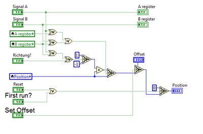
I'm using on my FPGA OR Quadrature encoder.
(http://www.ni.com/white-paper/6608/en/)
I add a few entries, so that its possible to set an offset value.
In all the VI on the FPGA, works very well with my encoder.
If I start the VI on my FPGA, the position value is 0, because of the "first round"? Element.
Now, I used the command of read/write in a while loop on my host VI to get the current value of the encoder.
After I start my host vi the defiler position always shows the value "2".
If I use the highlight function, the value remains at '0 '.
This is a really strange behavior, I don't know what can be the cause of this problem.
All positionsoffset values are 0 and encoders on my 9401 module entries are tied to the land.
The position value is only written on the fpga, nowhere else.
Anyone have any idea why?
Thank you very much.
-
Problem with the digital data to write VISA function
I have a GE's PowerPC that is running on the VxWorks operating system. I have a tornado application where I run my C code to generate a file .o & .out, then I empty image .o files & .out for PowerPC via FTP, now I need to communicate with PowerPC of LabVIEW (via serial communication using VISA vi) using the VxWorks controls. When I enter orders VxWorks in LabVIEW
That is to say for Eg: 1 > ls --> the contents of a directory list IE .o & .out files. The problem I'm facing here is, when I run the vi, I am able to read the file in the box to read the string but keep files on speeding up juice,
2 > ld <> --> load a module object in memory. I face the same problem here.
3 > then I need to type the name of funtion main c program, after which I can give input to the program.
4 > I need to enter numeric data as inputs to my program. but the write VISA function accepts the only input string and read VISA function gives only out of string... I want to give digital entries and read the digital output. Any help would be appreciated.
Hi Luke,.
You can try with this reliable hyperterminal VI.
-
Object LVOOP read/write using the API TestStand
Is it possible to read/write a LVOOP object to a variable TestStand from LabVIEW using the API of TestStand?
SetPropertyObject() takes a green wire reference, which is incompatible with an LVOOP object. SetValVariant(), SetValIDispatch(), and SetValInterface() seems to just write a value null of type variant. I don't know if I use the wrong API function or if it's just not possible.
Hi jsiegel,
That's right, it is not quite possible to what I believe, it is your intention. As mentioned, TestStand cannot create the object of LabVIEW. To make and use references of LabVIEW with TestStand, you need LabVIEW out this reference, which may then store it TestStand as an object reference. For VI requiring the obeject LabVIEW as an input, the registered object reference can be passed in. To make calls to LabVIEW classes using the class member call with a step of the VI Action instead of the call to VI for the Type.
Of course, you need both LabVIEW and TestStand 2012 or newer in order to use these functions.
Kind regards
-
Someone at - it an example of LabVIEW for I2C communication to read/write an eeprom?
I use sbRIO-9636 with FPGA.
I already tried with the "Advanced I2C" example, but it works...
Can someone help me?
Another suggestion:
You know about the VI package manager? There, you can install an application open source I2C & SPI API (worms. 3.0.0.22). It is an easy way to implement a system of Bus I2C on an FPGA target.
In this way is a little bit smarter.
Maybe you like it.
-
under condition of read/write terminals on the side of the connector (basic training 3)
Hello
During my practice towards the review of the CLD, I examine the Core 3 online training material too. I just read a few tips of 'best practices' on the forum, for example this post:
It should be noted, that we should not use terminals (which are on the connector pane) to the inside of while loop or condition of the structure. Neither control, nor indicators (read/write terminals): "terminals conditionally read or written on the side of the connector are BAD!"
I can find many examples in the online training materials, when the indicators and controls are placed inside while loop and the case of structures in a Subvi.
I guess I should not do this during my review of the CLD, as they will run benchmark on my project? Should not be the core training materials updated some time? Or it's just not too important to have terminals on the outside? I would lose points during the CLD Exam my project as in the Core 3 screws?
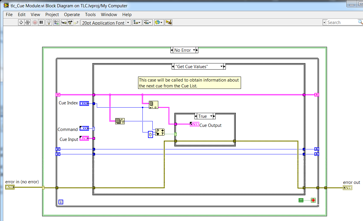
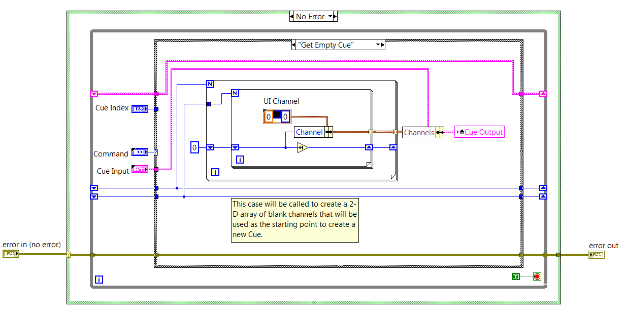
example 1: Core 3, exercise 4-6 design of an error-handling strategy:
EDIT:
What's even more ugly in this project, is that, in the case of 'Get empty Cue', the Cue output indicator is updated via a local variable, because the indicator is not accessible via 'outside ': wire
Nice catch on the training material. that the application would take an if subject to a review of the CLD test graders.
As noted in the nugget: sentencing of perfomance for conditionally reached terminals is a function of the size of the data. So, it is sometimes acceptable for simple data. The larger point being to learn about compromise and make the right choice for your code.
Preping for the CLD on other means of hand knowing that VI Analyzer will run on your project. Like any other code review you walk in - know the guidelines for the review and code to ' review ' as well as 'reply spec.'
I've not seen an instance where an example of shipping (2013 and later versions) would fail this test VIA (there are a few screws deep inside the vi.lib which can date back to before the adoption of this recommendation from style)
-
Frequency of calls to control for the FPGA read/write
Hello
I use a cRIO-9076 with a module NI 9476 DO spend some faucets. It is sometimes necessary for faucets with a pulse time down to a few ms of impulse.
The FPGA VI Gets the power tap queries, executes a logic of security, and routes the numerical results for the exits. It gets applications power of the VI on RT target that uses the function ' Read/write FPGA control' interaction programming of the FPGA VI front. The loop on the RT runs with 1 kHz, no iteration is missed. That means, it should be possible to switch the valves with a resolution of 1 ms.
What I see on an oscilloscope, is that the output digital are high for multiples of 50 ms, the system does not reach the valve for example 80 ms pulse or pulses shorter than Ms. 50 is a kind of limitation for calls of "FPGA read/write control"? I tried both options for arbitration, but it does not help.
The best knowledge of the limiting cRIO/module/features or ideas? Thank you in advance.
Karsten
Hi Karsten
You use any time in your FPGA VI?
It is useful to your code by sending as an attachment so that I can have a look.
Kind regards
-
Effective use of the FPGA read/write
I am writing an application for a CompactRIO real-time and I am looking for ways to simplify my code and reduce the CPU usage. I use FPGA to do much CAN e-mail and signal processing, then I have a VI running on the real-time processor that reads values in the FPGA, does some processing and outputs data in the FPGA. My code running on real-time parallel uses several loops running in a master/slave architecture. A single loop reads all necessary information in the FPGA in indicators and writes the values of the controls in the FPGA. The other loops read entries and manipulate the outputs via local variables.
My question if it would be more effective to get rid of the loop which is dedicated to the communication of FPGA and has of each loop to read and write directly on the FPGA. If I use a reference block FPGA open and use the reference of the output in several loops, each read/write operation block others until it's over? Each output is changed only in one place in the code, but there are several entries that are used by multiple loops. It is even more effective for each loop of read/write for the FPGA on request? How will this affect determinism?
Thank you
Jon
Jon,
Read/write controls is not deterministic, but I think that your previous method should work just fine, as long as you have that unique writers. If you have multiple writers, you start affected by race conditions.
I don't think you will see a significant improvement in the performance/CPU in the alternative method. You would see big performance gains if your master loop reads more slowly indeed, but it's always a compromise.
-
Difficulty using the binary read/write
Hello
The binary read/write function somehow not working properly in my application.
I have one store a 2D strign binary array. When the user closes the application, the application stores the values in table in the Bin file.
N when the application starts, it reads the file and displays its contents on the table.
The system works well if the total size of the content is 3 bytes. But if the size of the content is greater than 3 bytes, the program simply returns a NULL value at first when I read the Bin file.
How to save:
Convert 2D in String table using "Flatten the string" fn and to save in a binary file.
Procedure to read:
read a binary file. convert the output string table 2D using 'string Unflatten ".
I enclose my code here. PLS, have a look at it and let me know the cause of the problem.
Ritesh
I don't understand why you're flattening of a string, a 2D channels table. It's redundant. You seem to be also the substitution of the default big-endian to little endian byte order. You try to save it in a format suitable for other programs on other platforms?
If this is not the case, all you have to do is:
-
Feature SoftMotion Straight Line move read/write Targ Pos
I read up to / study code on the packaging SoftMotion example of OR.
I downloaded the code 'NOR week 2008 SoftMotion Development Module 2.1 and Compact 6-axis coordinated Motion Demo RIO' to discuss how I can implement a routine of homing on motor axes stepper and ran through a code without papers.
I note that property to move to right Linr Targ Pos RW (target Position) can take in a meter target or the target tables. The detailed help for this node does not detail the difference in operation.
From what I can decipher, it seems that the table entry is for when you have mapped to several lines of a 'coordination' and the entry in table defines the position of the target for the individual axes in the coordinate.
Is this true?
Hi Rvallieu, you are right. It is the function that the table has. If you configure the system to work with multiple axes, the Position of the target of the right line to move read/write will have an entry level. This is something that should be mentioned in the help. This was reported to R & D (# 133028) for further investigations.
-
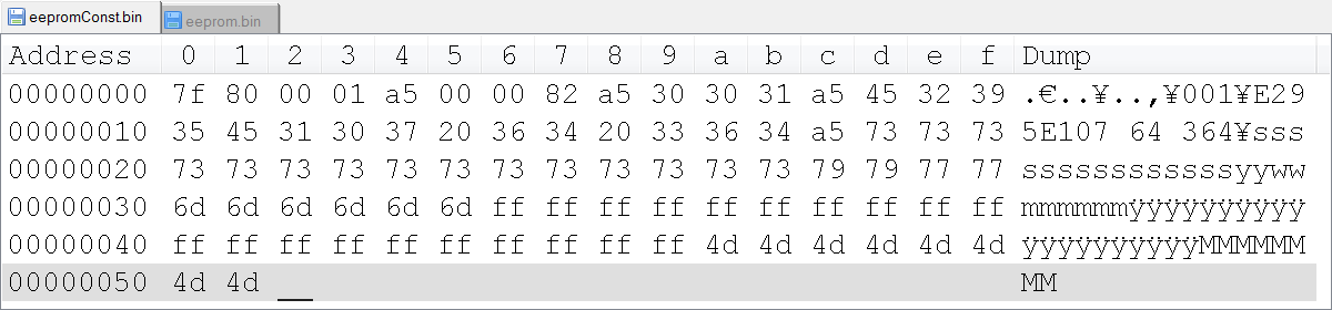
Read/write file binary change greater than 128 bytes.
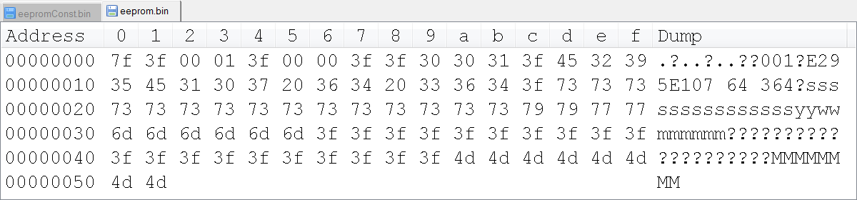
Hi all, maybe a strange question, but I'm scratching my head on this one. There is undocumented behavior in the function of read/write binary file, where U8 a value greater than 128/0 x 80 get automatically converted to 0x3F value?
I try to use LabVIEW to generate a binary file custom that we'll load in an EEPROM, so all data in the binary file is stored as values of U8. I have a "template" file, and eventually I'll take the logic implemented to replace the fields with the data from the true value. However, I am struck by the anomaly that when I just read the file in LabVIEW and then réécrirait, all the values 0x80 and more are truncated to 0x3F value. Has anyone seen this before, and is there a solution?
I noticed writing the value 0 x 80 directly to one generates a binary file (such as a U8) 0 x 90, 0 x 70 being written in the binary file. It is also rather undesirable, as it adds additional bytes in the bytestream, and the bytes of EEPROM must be in exact locations.
Join your data file.
This program is to give the images below? Are you sure that LabVIEW is to write the bytes differently? I really doubt that.
-
How to check the instance datafile I/O? solve the high physical reads/writes?
Method-1
identify 'hot spots' or I/O contention
Select NAME,
"Physical reads," PHYRDS
round ((PHYRDS/PD.)) (PHYS_READS) * 100, 2) «Read %»,
PHYWRTS "physical Scriptures."
Round (PHYWRTS * 100/PD.) PHYS_WRTS, 2) "% of writing."
FS. PHYBLKRD + FS. PHYBLKWRT "Total block I / O of.
de)
Select sum (PHYRDS) PHYS_READS,
Sum (PHYWRTS) PHYS_WRTS
v $ filestat
) pd,.
v$ datafile df,.
v$ filestat fs
where df. FILE # = fs. FILE NO.
ranking by fs. PHYBLKRD + fs. PHYBLKWRT / / desc
Another method-
On Oracle10g, CWA also provides the dba_hist_filestatxs table to track the disk i/o:
break on begin_interval_time jump 2
column phyrds 999 999 999 format
column begin_interval_time format a25
Select
begin_interval_time,
file name,
phyrds
Of
dba_hist_filestatxs
natural join
dba_hist_snapshot;
It is - method that you use to check for errors in data I/O file? AND how to solve high physical reads and writes?Ankit Ashok Aggarwal wrote:
AWR project stat e/s in terms of segments, query and etc.
Here, my concern is what should be the value of ideal threashold for a DBA to act on the high physical reads/writes?
and how he can fix this problem if it affects database performance?I don't think that there is any possibility to mention that the amount of an e/s is going to be good or bad for a database in general. The reason is that it is not quantifiable. For example, in a store, maybe one day that no one gets and another day, there is no place to stand (because there was a sale announced by the store). So now, how do you say that it was not necessary? Rather than search for best practice values, it is best that you keep track of the normal functioning of your db and when you see a special summit in the values of events scattered user IO as DB file read, DB file parallel read etc and when this happens, you should check back the work you are doing and see if that can be refined somehow.
Aman...
Maybe you are looking for
-
Repair your startup disk Bootcamp disappearing after you create the new partition
. After some research, I found that it was the way forward to create a separate partition, and so I did another partition. I didn't know it would affect my Windows partition that I thought it was completely different. So now, when I start it up, ther
-
Can I plug my superdrive drive in apple tv to play dads?
Am new to Apple TV and do not have a reader dvd or another device plugged into the TV. Can I plug my drive superdrive USB port of Apple TV to play dads?
-
my iphone keeps restarting randomly 5s
HI, so my iphone 5s just started rebooting randomly. wouod screen turns blue, then turn off and restart. I've also updated my phone to ios 9.1 last night. I got my phone taken far sunce August and I just returned it yesterday but this thing restart j
-
question about the input impedance
Hello world I tried to measure a voltage with internal impedance 10kohm source, and I connect to the source directly with the NI USB 6009. When the voltage source is 5.043V, the data recorded by labview are about 4.8V. I checked the manual of the USB
-
List of burner windows dvd maker, no burners are shown. my cd - rw drive does not work properly. Creation of dvd uses a different burner? How I'd get it in the list of burner?