Using the CRio NI9265 module as current source
My apologies for what is pretty basic - I come to this Chem Eng background rather than electric. I have a CRio-9012 controller with a 9265 module 0-20 my (among others). The power supply to the CRio is 24VDC. I want to use one of the outputs as input to a power controller Watlow DIN-a-mite, which will lead in turn 10 a / 2.5KW heating.
The datasheet for the power controller indicates that the input command is powered by current loop linear, 4-20 my DC, requiring an available with 6.5 VDC power source. Am I right in saying that I should compare 6.5 VDC voltage compliance for this module (12 DC max), so this arrangement work?
Kind regards
Chris.
Hello ChrisTighe,
That's right, that the installation will work.
The 9265 will display up to 12 VDC, and your device requires a maximum of 6,5 VDC.
Tags: NI Hardware
Similar Questions
-
Using the NI 9403 module as a source of tension for its own entries
I need to have certain diagnoses in a circuit that I build. I plan on the use of certain relays to throw a switch when certain events occur. This switch would be connected to a digital input NI 9403, as a way to detect the event.
To do this, I need power the switch itself, so he spends a tension that the NI 9403 module consider a digital camera 'high '.
Can I buy a power supply of 5V, but is expensive compared to what it should only do. I was wondering if it's permitted use / safe / sane... at one of the NI 9403 pins as a digital output and use it as a source of tension for switches? According to technical data sheets, I should be fine for power supply. I'm not sure if it's a decent way to do this.
My finished project requiring a current amplifier Board, I had to weld. So I decided that I might as well just add a voltage regulator to this Council and some resistance to simplify power. I never tried to use the NI 9403 module as a source of tension.
-
Resources on Rio fpga using the NI 9403 module
I use a CRIO and it works very well with my A/D and D.-a. When I add an e/s digital NI 9403 module, it eats all my resources even if I don't use all that in the circuit! Is there a way where I can use say only 2 or 3 pins e/s and not other use without him swallow all my resources.
I found the problem. When I added the module e/s I used the mode of discovery and he went. It seems it went past Scan mode for some reason any. When I moved the unit on Solution Explorer up next to two other files, I had made A/D D - A mode FPGA, he changed his mode of FPGA itself and then I could remove I/O pins as required. The icon, then changed when I pulled a PIN on my FPGA block diagram and everything was ok.
-
Use the cRIO as output RS232 port
Hello
I'm working on a cRIO-9002 with a NI9215 AI module. I send the command to the cRIO by an ethernet cable and I read signals of external devices with the module to HAVE it.
My question is about the cRIO RS232 port, I know if I can use it to send data of FPGA for PC? And if I can, how?A quick response will be great, just to drive me on the right track.
Thank you.
Maxim
That should be no problem for you. I would use normally tcp to make the comms but of course series is possible.
Michael -
Serial numbers for the cRIO-9081 Module
Is there a way for the FPGA in the cRIO-9081 to read the serial number, date of calibration of the NOR-9201 module installed in the cRIO?
I want to get this information and send it to my Host.vi, because we have a duty to provide information instrument document during a series of tests.
Thank you
Paul
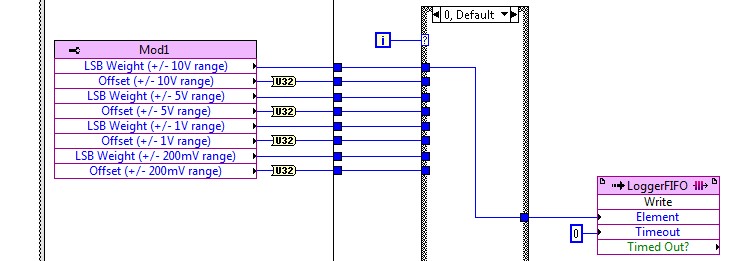
Use a property node of the module to read the number of series/VendorId... but the calibration date is not stored. (FPGA code example shows NI9205 data)
Here a Fifo of DMA target host is used to send the data to the controller of the CR...
-
Using the SCXI-1520 module for measurement of torque
Hello
I'm working on a project that requires a measument couple in real time on a speed-shaft drivetrain configuration phase.
I have the SCXI-1520 module, and I think with a with a configuration of full-bridge strain gauge to do this.
The problem is that it is not possible to connect to a real-time measurement, so my first solution was using some sort of wireless transmission to receive data in the SCXI-1520 module
The Arduino + Xbee seems to be the best way to go, but at the same time, I think I might have a few problems of conditioning of the signal while transmitting data to LabVIEW through the SCXI-1520.
Don't you think it's the best way to do it, or is there a better solution?
Thank you!
Hi Kenny,
What type of operating system are you using? When you say 'Real time', do you mean look at a signal when it occurs? If you use communication networks, you will not be able to get truly control in real-time because communication networks is not deterministic, and you cannot guarantee the synchronization.
If you try to get a signal and he discovers that you buy it, you should be able to use the Arduino and LIFA with LabVIEW. Adding the SCXI-1520 will not add any additional resolution in this circumstance.
Best regards
Anna L
-
Use the same code module to multiple steps in the sequence
Hi all
I tried to implement a sequence that uses the same code for all steps module in the order, but I'm not returning to it when I need to send it commands. I got regarding the appellant the VI in a new thread so that it can be executed asynchronously. I can run the simple sequence and it will indeed open the VI and move to the next step. When I close the VI manually from the front, the TestStand sequence is completed, as planned. So it turns out that I have a lot more work.
My question is how to call the thread separate from the main sequence and other sequences overtime when I need to change the settings. If I insert a step in the Action, I have to select a file of VI, but from what I can tell, it opens another instance of the file and does not provide an interface with the other asycronously running instance. My next guess was to use a stage of education, but I was not able to understand how to configure the search string to call the VI settings. In addition, I don't know how to proceed. Please notify.
My intention is to start the module code (asynchronously) VI, run several different subsequences in the main sequence, which call this same VI and edit its settings, close everything and report the results. If I'm understand how TestStand is supposed to work, please let me know.
Thank you
GSinMN
What I do is use a queue to send data to the asynchronous VI. So he can run and whatever, but also receive orders from the queue. I use a motor of Action that contains the reference to queue and sends the commands. If you really just call the engine of the Action of your sequences.
-
DAQmx 201105 error using the cDAQ 9403 module
I'm using the DAQmx C library of Borland Delphi programming. My hardware configuration is a cDAQ-9174/9178 with a 9222, 9401 and 9403 module. Here's where I manage problems at the moment:
I want to run three different tasks on my 9403 module:
Task1 is an output buffered with frame sample clock/cDAQ1/do/SampleClockTimebase to 100 kHz (channel 0-5)
Task2 is a software-timed output (20-25 channels)
Task3 is a timed software entry (channels 26-31)
Task2 and Task3 me give 201105 errors when I try to use DAQmxWriteDigitalLines and DAQmxReadDigitalLines, respectively. Create channels for these tasks works very well, however. Apparently, there is some reason to believe that the 9403 won't perform Task1, except that it works without raising errors. This work by accident and only because I am using channels 0-5? That's why I'm getting errors when trying to use the tasks 2 and 3?
Any thoughts are appreciated.
Hi André,.
This is expected behavior and is documented in the digital i/o considerations for devices of the series C using DAQmx.
The 9403 is registered has a series module that has the following restrictions:
- You may not use modules series and parallel together on the same task timed material.
- You may not use modules series for the trigger.
- You can do static and timed tasks at the same time on a single serial module.
- You cannot material timing in one direction at a time on a module in the two-way series.
You can do task 1, or you can do tasks 2 and 3. You can not do the tasks 1, 2 and 3 together, as you saw. You can do it with an additional 9403 if you move the software tasks timed to the other module.
The 9401 is a parallel module that does not have these restrictions. Snacking is configurable, however, which means that you must set the direction in groups of 4, but it seems that you are using too many lines for a single 9401.
-
Not possible to use the Nvidia GPU both graphics primary source all the time?
I went through the manual and the tips of help from Lenovo and it seems that it is not possible to use the NVIDIA GeForce 840 M, 2 GB as the exclusive GPU card.
The only control that I can find is one in the Panel of 3D graphics and if I read this correctly it assigns that Nvidia will be used when require it strong application processes (I'm guessing games play?) but for activities such as photo editing, it is up to the intel sur-bard chip
brian1208 wrote:
I went through the manual and the tips of help from Lenovo and it seems that it is not possible to use the NVIDIA GeForce 840 M, 2 GB as the exclusive GPU card.
The only control that I can find is one in the Panel of 3D graphics and if I read this correctly it assigns that Nvidia will be used when require it strong application processes (I'm guessing games play?) but for activities such as photo editing, it is up to the intel sur-bard chip
To force an application to use your NVIDIA graphics card, right click on its shortcut (or an .exe file), point on run with graphics processor and select the NVIDIA processor high performance.
-
Problem with the lines using the printer power module
Printing from your computer or copy it using the bed of glass is very well, but when we use the document feeder, we get dark vertical lines. I cleaned the glass and the rollers I could have access, but it is not improved. Any suggestions? Thank you.
Glad to hear that you're back on

 .
. -
entry of mV/psi for SCXI-1102 using the SCXI-1308 module?
Is there a way to physically connect a mV/psi signal to an SCXI-1102 module, which also uses a block to connect SCXI-1308? What I've read, the terminal block can use only a signal 4-20 or 0-20 Ma, right? I don't see the pins that the terminal block plug to use for output of the pressure sensor mV.
Thank you very much for the help!
TQ
Hi FMC_Pumptest,
The 1308 Terminal is designed for the current input. You are right that you have entered for 0-20 mA and 4-20 signals my with this block.
Kind regards
-
Cannot send DIO siganl using the LabVIEW FPGA Module and MyRIO
Everything works when no FPGA is used. If the circuit and harware work.
However when targeting module FPGA MyRIO, acquiring data and processing the work and the signal to the engine's 'sent' (visible when executing Hightlight is on). But there is no tension on the DIO ports used. FPGA projects includes VHDL code.
Do you know what could cause this problem?
You must control the OID in the FPGA.
-
Luminaire 3s 8962. Cannot use the GPIO C pins as a source of disruption.
I'm trying to use GPIO C-5 as the source of interruption to run a vi and get this error
Building target "LabVIEW".
compilation of ARM_irq.c...
.. \Drivers\Interrupt\ARM_irq.c(313): error: #20: identifier 'LM3Sxxxx_GPIOCHandlerP' is not defined
Target not createdIt works when the selection of the GPIO groups a, b and d...
David
Open your project in Keil uVision and make a small change in ARM_irq.c/line 225:
LM3Sxxxx_GPIOCAHandlerP to LM3Sxxxx_GPIOCHandlerP
ARM_irq.c is in the "target drivers' group of the LabVIEW project.
To make the change permanent, you can use GPIOC future projects breaks, also change the template file:
\Targets\Keil\Embedded\RealView\EK-LM3S8962\Template\Drivers\Interrupt\ARM_irq.c -
Tecra S3 - cannot use the new RAM modules in the B slot
Hi all
I just bought two RAM modules of 1 GB to replace my old 512 MB one. This, as far as I know, is the maximum allowed by my Toshiba Tecra S3 (PTS30E-01000QSP).
When I put a module in A slot, the machine works perfectly; If I place a second in location B, the computer tries to start but, at a time given, it freezes just (no activity of the HARD drive or changes on the screen) and the fun begins racing on as if some process crashes in the CPU to heat that make it up. At this point, I was always afraid that the heat can damage the computer and be turned off by pressing the on/off switch, so I can't tell if the problem is solved simply waiting.
I swapped the two modules on A slot and the two work well when they are the only one on the machine. Pretty funny if I place (as is the case now) has the old 512 MB in the location B as well as a single module of 1 GB in slot, it works!
My BIOS has been upgraded to the last, that I could find in these same pages (version 3.20 if I'm not mistaken), but it made no difference. If I enter the page of the BIOS when the two 1 GB modules are present, the BIOS recognizes that they are there. This behavior occurs when I try to start Windows or Linux.
Honestly, I'm puzzled. Someone has an idea what can happen and how I could place the two modules on my machine?Thank you very much and sorry for the long post
O.
Hello
The modules you purchased exactly for your Tecra S3? Maybe that they are not compatible with the laptop and it hangs after a few minutes.
Normally, the Tecra S3 can handle up to 2 GB and that means 1 GB in each slot. For modules of Toshiba part number is PA3411U-1M1G.
In my opinion you should try it with other modules with original 512 MB module everything works so I guess your new RAM is the cause of this problem.
-
OK with photography package creative cloud why did it let me use the lightroom develop module?
I tried to find an answer to this, and he told me to buy a subscription. I bought the package of photography creative cloud for 9.99. It is supposed to be included I thought.
Download you and install the program?
To start https://helpx.adobe.com/creative-cloud.html the Cloud
-Installation, update or uninstall and launching after installation
Or, https://helpx.adobe.com/manage-account-membership/cc-reverts-to-trial.html
Maybe you are looking for
-
How can I get the correct AppID is displayed?
On my iPad, I'm registered on an Apple ID. Then, I signed up with my other. Then, I go to an app, that I bought, on the iPad. When I try to restore the version full that I paid for, the former Apple ID appears, even if I signed on that one and with a
-
Is there a way to avoid having to turn off an iMac runs OS x if you want to exchange for Windows? Thank you
-
My MacBookPro early 2011 screen 13inch goes black
I am having trouble with my early 2011 MacBook Pro. It does a few things. When I open files or Chrome applications, the window becomes black for a bit before loading of the real thing, that I open. In addition, sometimes the whole screen just disa
-
HP ProDesk 600 g: PCI Simple Communications Controller
Have just reinstalled Win 8.1 X 64 on my system after replacement of H/D using HP provided disks. Noticed I had three errors re no driver installed. Resolved to the third question but have tried various links on the forum but with no joy re these det
-
Looking to buy Chromebook 2 CB35 C3350 to the United Kingdom
I am looking to buy the Chromebook 2 (2015), FHD IPS to the United Kingdom. The model number is CB35 C3350. I am struggling to find vendors online and otherwise. Where I would be able to buy one?