Integration of Code FPGA on the rest of the project.
Hello, thank you for helping me.
I recently started on the MyRIO, NOR I have the following code to handle a ultrasonic rangefinder:
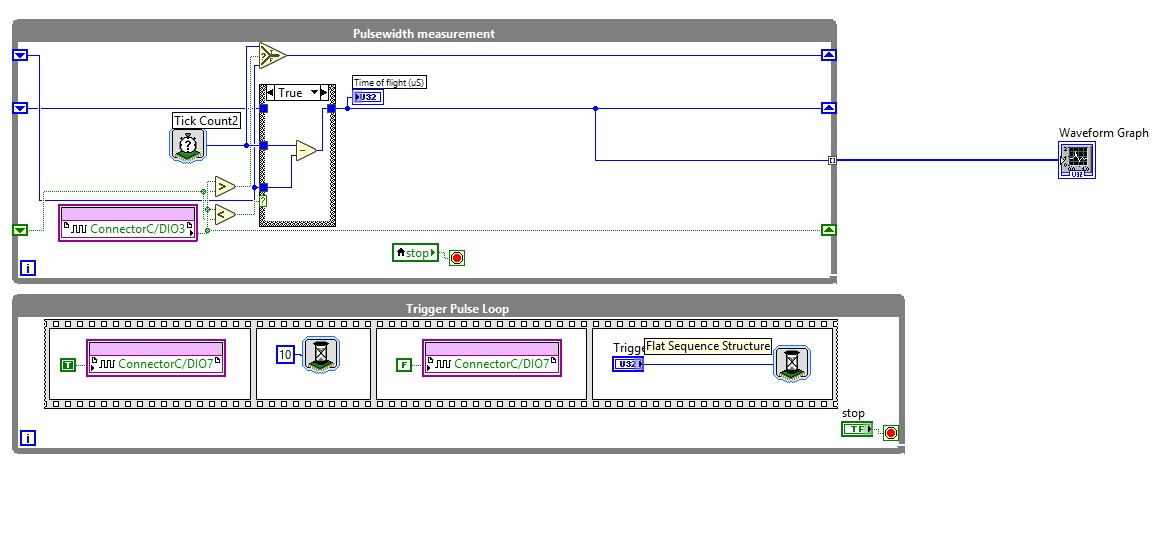
However, when I try to compile I get the message:
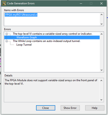
Apparently many of the most common features of Labview can not be used on a FPGA target. However, the code for the Rangefinder is a small part of a larger project in which I have to use such functions, so my main concern is the weather, I'll be able to integrate this code with 'normal' labview FPGA code on the myRIO, if possible, how?
I would create as for example a 'top' VI which has its own code (showing the waveform graph after the realization of certain mathematical operations on the will appear given by the VI as well as some other stuff).
Thanks again for helping me.
Here's the thing with FPGA: you configure real equipment. Everything must be fixed to the size. So if you don't have to use an array, you must configure it to be a fixed size (right click in the control to set the size, use the table to initialize or LOOPS containing a fixed number of cycles, and autoindexing).
As GerdW said, FPGA is not a GUI. So, you will want to use a DMA FIFO to send your data to waveform until the RT. You create in the project.
For some really good information, I recommend that you see the cRIO Developer's Guide. The myRIO is the exact same platform as a cRIO except that you cannot use the C Series modules.
Tags: NI Software
Similar Questions
-
How can I change the clock from the fpga to the entire code
Hi I am new to the labview and using 8.6 demo (fpga modules in real time).
I developed some codes to practice and you want to change the clock freq 200 MHz of 40 M for all codes.
I mean how to use clock derived for my vi.
You create a clock FPGA derived from the "clock of 40 MHz on board" in the project manager.
Then in the properties for the FPGA, you can select 'Top level Clock '. High level for the FPGA clock can be that what follows: 80 MHz, 120 MHz, 160 MHz, 40 MHz, 200 MHz
-
Hi, just got my new cRIO-9067. I have converted my project over the cRIO-9067 since the cRIO 9074. Same layout module, same engine, same scan code custom fpga, (hybrid mode). I have no problem of compilation for the 9074, which is a lower performance FPGA architecting the 9067 FPGA.
The final timetable for windows compilation shows that the timing is respected for all clocks - 40, 80 and 120 MHz (I use a clock derived for some code sctl). During the end of compilation, during the phase of gen bitfile, I get the dreaded time violation. Investigation of the breach indicates that it is not the custom code, it is not schema components. One of them seems to be linked to the card series OR 9870 I in the chassis.
Why? Is there anything I can try with the compiler directives for this problem? You would think that it would be easier to compile for the highest performance FPGAS...
OK, don't ask me how I thought this output - to run I changed nothing else than this: feed the I/O node a reference FPGA of e/s instead of configure the node via the menu "link to. It makes no sense, but the compilation succeeded when I did this.
I know it is because I created a very simple test VI in my project and made sure it does not compile without it.
-
Numerical simulation of e/s of FPGA on the development computer - strange results... Help, please
Hello
We ordered a 7851R DAQ card which we
have not yet received and we try to simulate using the
Setting "computer development". However, I can't seem to get the OID
to work properly. In fact simply opening "digital line input and.
Example of output.VI' does not have to wait for results. What happens in the
example of file is just, the indicators flash constantly and are not affected
by controls. Is this a known problem and I just need to wait for my
material or have I done something wrong?Thank you!
Michael
You don't mention what version of LabVIEW you use, but if
you use a LabVIEW 8.6, there should be basically 3 options for
Debug / simulate your VI on the development computer.The
first is to run the VI on the development computer using random
data for FPGA of e/s data. I suspect that this is the option you
currently using and only can be useful if a large number of logic in
your VI depends on the values of the e/s database.The
second option is to use a custom VI which provides FPGA simulation
E/s data. That sounds as if it was what you are looking for. When you
Select this option, you will also get a button you can
Press to create a VI model that can be used to create your custom
VI. If you look at the diagram of the VI model, I think that it
should be relatively simple to understand how to insert your
custom code.The third option is to run the VI on
the host but the use of I/O of the real world. In the latter case, a default value
bitfile is automatically downloaded to the FPGA for you and the data is
transferred from the device by the driver. Of course, you cannot use
This last mode until your material does indeed. I hope this helps. -
Code reuse within the same VI (when he's not a Subvi)
My last question here was awarded a point congratulations "to have been a big question", which is quite annoying, because my current skill level, it is hard to imagine the time when I will never be anything other than a "taker" of this forum! So this is with a "dumb" question to try to put the right folder.
My front panel has 17 groups of one button + three numerical indicators, it's quite a few elements of façade and 8 groups have an enum indicator as well. All of these are also controlled by the visibility property nodes or 'off '.
My program gathers all data for these elements in a table at the end of the main loop and functional global variables, it refreshes the properties and values of all these elements of façade. It might sound like undisciplined, but because of the similarity between the 17 groups that refresh the elements panel above all happens within a pure FOR loop (albeit with a structure AFFAIR of 17 channels inside) if these controls are at least not sprawled all over my block diagram.
The only problem I have is that my program takes a few seconds to initialize and get the loop running, period during which the façade shows garbage (well, maybe not garbage, data maybe related to the last time the program was executed, which may have been a context different, so much better if not visible).
But if I also ran the same right 'before the code refresh of the Panel"after initialization (wipe) the data in my functional overall, the result would be that all of these controls would be invisible or disabled, which is a much better place to start from.
But what I need to put a copy completely separated from the loop on my block diagram to get this effect?
Make a sub - VI is out of the question, because it's the front of this VI that I'm working on.
The word that describes what I want to do (for me) is "subroutine", but in LabVIEW "subroutine" seems to have a very specific meaning, a VI "stripped for speed" that affects no front panel in any case.
Is this just a problem of my state of mind? It is true that in my life by far most of the code I wrote has been assembler for microphones integrated 8-bit, these applications are always tied to memory. At this stage of my career balance reverse but many high-level code I write (Yes, I am a dinosaur). So I tend to worry about the what will be my compiled code. Should I just put another copy of the loop (in fact, it is only the nodes of property 'visible' 76 I need) on my schematic and disturbing stop on this subject?
A number of observations.
(1) the title of dinosaur not is still FRO seized with many of us competing (I used as well to play the game of 'ICan write this charceter to X lines...) »)
(2) when you do a lot with the GUI, "David FP updated (this is a property of the FP to stop updates of the screen, serach for this) may spped things upward."
(3) I use a GUI controller very often in my applications. I posted about it here.
(4) if Chase you my tags I have a collection of GUI performance.
I put the code in a VI called from my GUI controller (who calls your FG for the info).
Regarding the memory
When we used to depend on someone with a crochete crochet and beads to make our memory, it was justified. Today, memory is cheap and using you save time is fine. When you worry about memory, it's when you find that the code does not fit into 2 G more.
Ben
-
You try to run the scan mode and mode interface fpga at the same time is causing errors
I'm reading a 9236 9237 and a 9215 with the scanning engine and read from two 9211 modules with the fpga. It's because I need to acquire to 200 Hz with the 9236 9237 9215 but maximum rate of the scan engine is limited by the slower module in the system, which in this case is the max of 15 hz the 9211.
So to use both interfaces (scan engine and fpga), I followed the percisely given in this article for instructions.
1. the project has created and added the peripheral crio using the interface of the scan engine.
2. Add the target fpga and drag and drop the 9211 inside modules
3. has created the fpga in interface file with and compiled with no error.
4. interfaced with the file fpga at almost exactly the way the sample project of "getting started with 9211' by using the engine of analysis in the interface with the other modules.
5. after the errors to discover that I created a VI that tests for just the portion 9211 code (called "thermocouple FPGA method Test.vi")
The data returned by the interface fpga was nothing else than zeros on all channels, even if thermocouples were hooked on some of them. (all zeros as entries in the convert temperature vi gives-410, 6160 degrees F, if you happen to have the material to try this.)
I get the following error from the open fpga vi reference:
code error-61141
"Thermocouple method Test.vi FPGA.
Activities FPGA:Open FPGA interface reference.
Reserved outside LabVIEW FPGA: turns The RIO Scan Interface. You must set the mode Interface FPGA chassis in order to unlock the FPGA. »It's extremely frustrating, because as I explained, I've been very attentive not only follow the instructions for concurrent fpga and analysis but also to model my VI by the example of VI, even if only for the moment, just to try to work things out.
Any help would be appreciated as I need to fix this for the further development and I am somehow in a lack of time. I opened a support ticket (reference #7256226), but the app engineer had no time to answer.
My system:
cRIO-9014 controller RT with crio-9104 bottom of basket.
LabVIEW 2009
Latest drivers and peripheral software pc and rio (RIO scan 3.2 engine support june2009)
rex1030 wrote:
I'm reading a 9236 9237 and a 9215 with the scanning engine and read from two 9211 modules with the fpga. It's because I need to acquire to 200 Hz with the 9236 9237 9215 but maximum rate of the scan engine is limited by the slower module in the system, which in this case is the max of 15 hz the 9211.
This should not be the case. 9211 data will not update with each sweep, but you should be able to run the scan faster than 15 Hz without problem. Do you have specific issues with this?
So to use both interfaces (scan engine and fpga), I followed the percisely given in this article for instructions.
1. the project has created and added the peripheral crio using the interface of the scan engine.
2. Add the target fpga and drag and drop the 9211 inside modules
3. has created the fpga in interface file with and compiled with no error.
4. interfaced with the file fpga at almost exactly the way the sample project of "getting started with 9211' by using the engine of analysis in the interface with the other modules.
5. after the errors to discover that I created a VI that tests for just the portion 9211 code (called "thermocouple FPGA method Test.vi")
You can try making sure that the chassis is set to mode Interface FPGA and the setting is deployed. I wrote that article that you referenced says will select the deploy option later and not explicitly speak to deploy the chassis later. Run a VI with a reference open FPGA vi not automatically deploy chassis settings if you need to do it explicitly. Try the following steps.
1. right click on the frame element and select Properties. Make sure that the Interface FPGA option button is selected. \
2. right click on the frame element and select deploy.
3. repeat your VI.
The data returned by the interface fpga was nothing else than zeros on all channels, even if thermocouples were hooked on some of them. (all zeros as entries in the convert temperature vi gives-410, 6160 degrees F, if you happen to have the material to try this.)
I get the following error from the open fpga vi reference:
code error-61141
"Thermocouple method Test.vi FPGA.
Activities FPGA:Open FPGA interface reference.
Reserved for LabVIEW FPGA outside: The RIO Scan Interface is running. You must set the mode Interface FPGA chassis in order to unlock the FPGA. »The likely cause of this error is that the setting of the FPGA Interface on the chassis has not been deployed. If the chassis is still Mode Scan fixed personality bitfile will be loaded on startup and the FPGA will be locked.
It's extremely frustrating, because as I explained, I've been very attentive not only follow the instructions for concurrent fpga and analysis but also to model my VI by the example of VI, even if only for the moment, just to try to work things out.
I'm sorry that you have had difficulties. Assuming that I'm wrong about the source of your problem, it seems we have to update less than Ko to include the deployment step.
Any help would be appreciated as I need to fix this for the further development and I am somehow in a lack of time. I opened a support ticket (reference #7256226), but the app engineer had no time to answer.
My system:
cRIO-9014 controller RT with crio-9104 bottom of basket.
LabVIEW 2009
Latest drivers and peripheral software pc and rio (RIO scan 3.2 engine support june2009)
-
Common organisation of the project in real time Code
Hi people,
I'm working on a project of RT using several cRIO chassis.
I common code RT I want to use with the different cRIOs.
What is a good way to organize the common code within the project?
For example. I have the folder called "common RT.
It seems that I have to put the folder this folder under a cRIO special so that the screws to be recognized as RT
Are there other options?
Thank you
Steve
Laughing out loud
They will all point in the same VI and location but since each CRIO has its own compiler you must place the code under each cRIO.
But if you make a change to the VI under the cRIO it will update for the rest also.
-
FPGA: Change the sinusoidal signal generator
The sine wave in the FPGA palette generator, that's what I need to do
but he can't exit do 'cosine', which is outside of 90 degrees. I need 120
degrees. To avoid discouraging, I opened the façade on the sine wave
Express VI generator that turned into a normal sup - vi. I changed the
a digital constant corresponding to 120 degrees out of phase, and the name was changed
of the output pin.The module will not compile. First mistake was a wire that was a type of variable, the
Fix suggested to check a box for pre-allocating did not work so I made the table
the length constant of 1024 (that is, it is supposed to be). Following error was
that one line of vhdl file was too long (32 k characters for a specification of length 4 k max
characters).Just for grins, I put the original VI Express return with the release of cosine and
It builds correctly.There was a big damper on the modification of the vi. However, I didn't know that
simple conversion to a subvi and the tweak of a constant value would break.Is it possible to get an updated the express vi for this application, or advice on how
changing the text that is there? The compilation breaks mainly online VHDL
length associated with the range of 1024 points.I can roll my own generator of sinus by using some examples, not a big problem but
It will cost you some time. Another option might be to run two generators of sinus
and specify a different phase, but I'm not convinced that over time they
will be exactly synchronized. Change the Express VI is a much better
option.Thanks in advance,
Bill
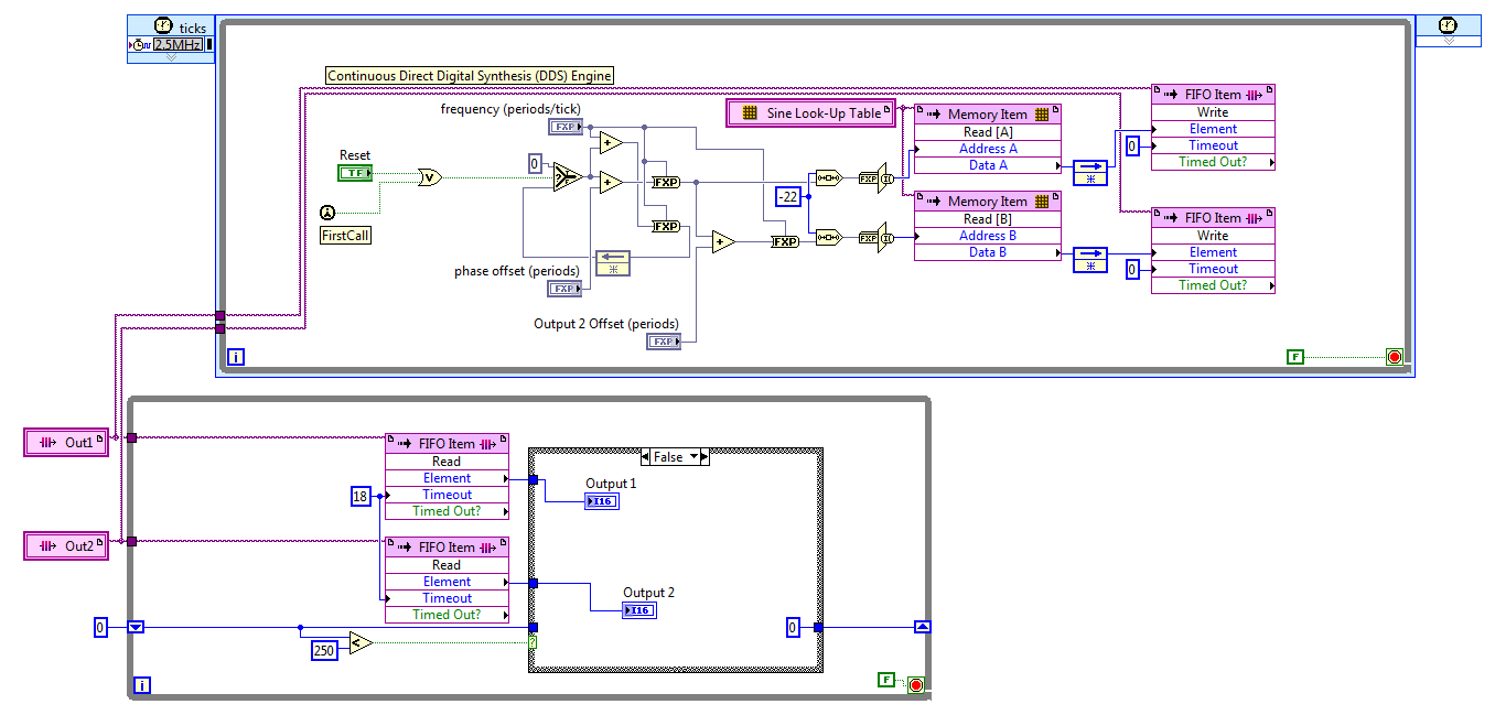
I discovered the hard way that LabVIEW 2011 has no records. After reviewing various options, I settled on the FIFO. The code presented here works well, but it is not save space on the FPGA to the wire using two generators of sinus with a phase difference in hard on one of them. For now, I'll use two sine generators, if this turns out to be unworkable in practice due to the relationship of phase adrift, then I'll look at it again.
The frequency and phase of the compensating controls are fixed point numbers formatted in zero whole bit and a 32-bit word. Bed down while the loop is synchronized with the loop timed by the FIFO, FIFO of 18 ticks timeout is two more than the 2.5 MHz in a loop which is a ditch-16. The IF block in the lower part, while the loop cut update control up to 10 KHz, 60 Hz sines more quickly.
Great experience, thank you for the help.
Kind regards
Bill
-
Original title: drive does not appear, difficulty he pilot installation fails, virtual drives don't work - same results if the material under tension
A few weeks ago, as my two DVD players (the two Samsung Lightscribe SH-S223Q of) disappeared after a repair installed, I did for the other problems (not sure if it was directly after installation because I don't notice it right away, but it was no doubt). In Device Manager, it gives the message:
"Windows cannot load the driver for this hardware device. The driver may be corrupted or missing. (Code 39) »
I tried the Microsoft Fix It tool (Mats_Run.dvd.exe) that detects the problem and says "Install device driver" in a popup, but then he says "software device driver failed to installed. At the end it says under the issue, the "CD/DVD drive is not detected" and the status of Fix 'not set '. Note that, when I boot from another hard drive (with Vista 64 on it installed from the same DVD, just a new installation) disks appear very well. Also I can boot from the drive as well.
I can't do a repair installation, since it must initiate Windows, and I can't load the disc. I tried to update my BIOS but that has no effect.
Recently I actually moved this hard drive to another one, with another brand of hard drive and all the rest. Just like before, if I boot from another hard drive (this one with Windows 7), the drive unit-a Optiarc AD-7230 s - looks and works, and I can also boot from the drive at startup. But since the drive hard as I want to use, the drive does not appear. Fix it, etc. Device Manager gives the same messages as before.
I tried virtual drives - Daemon Tools Lite and Virtual Clonedrive. When I try to add virtual devices to help, nothing happens. The new drive will be displayed in the Manager of devices, but with the same error Code 39 as the real drive.
What are my options at this point? How can I get the drive to appear or to fix my copy of Windows?
I could solve this problem. I started in Ubuntu and deleted the existing cdrom.sys, cdrom.inf etc. files (as in Windows, they were protected and I couldn't delete them), then I copied the files from another installation of Vista I had on another hard drive. After having done that, I updated the drivers in device, disabled/enabled readers and readers management that presented themselves.
-
How can I remove the code shipped since the beginning of all forwarded e-mail messages?
When I click on 'Advance' in an email, it shows the integrated top code which is followed by the actual email that I submit. I tried to change settings in the section of Composition of the tools, but that didn't fix the problem. I would like suggestions. Thank you.
We show an example.
I suspect it is as simple as the definition of view | Headers | Normal - I think that yours might have a value of "All".
-
I am currently working on a site that has the integration of Paypal which includes the page redirects (confirm or cancel). My goal is to have the implementation of site with a layout for desktop, Tablet and phone. My question is when I have a redirect page should I create a separate provision of the page for each device or just a provision of office that fits all three screen sizes? I hope that if the html page has the same name of the device (query) is automatically detected. Help with the help of Adobe Muse CC
By Payal integration, you mean paypal html button? or etc payment gateway configuration? If this is a configuration of the gateway to your site domain name then a single page with any structure will work, but if you use the button code for all associated formats then you will need to create separate pages for all.
Thank you
Sanjit
-
Checking the referential integrity of a form before the presentation of the Page element
Hi, OTN,.
I have a form on a table with multiple columns, some of which are foreign keys to other tables. Rather than validate the columns for referential integrity when the user inserts/changes in shape, I would use a dynamic action to attract the attention of the user with a javascript alert() when the user loses focus of the element. After a user enters a value into the text box and moves to the next item, I want to be able to query the table, check the existence of the value of the user and issue a javascript alert() if there is no match.
What is the best way to go about this?
I created a dynamic action-to run PL/SQL code on one of the elements of the page, with a code similar to the following:
DECLARE
rf_check varchar2 (30);
BEGIN
SELECT col1 INTO table_a FROM rf_check
WHERE col1 =: P1_ITEM_FK;
EXCEPTION
WHEN NO_DATA_FOUND THEN
HTP.p ("< script type =" text/javascript"> ');
HTP.p ("alert ("ERROR");");
HTP.p ("< /script >" ");
END;
I could not get the dynamic action of delivering javascript. Any thoughts?
Thank you
Matthew Moisen
Published by: Matthew Moisen on 25 October 2012 14:22Matthew Moisen wrote:
What is the best way to go about this?I have to admit that I've never tried, but I would be surprised if Javascript back via statements made htp.p that they are actually executed by the browser.
I would do something like that, by a dynamic action that calls an application process. The PL/SQL procedure request would return via htp.p OK or ERROR. From this result, the javascript would determine to issue the alert. Something like the following (not fully tested):
Javascipt var get = new htmldb_Get(null,html_GetElement('pFlowId').value, 'APPLICATION_PROCESS=FK_CHECK',0); var fk_check = get.get(); if (fk_check=='ERROR') { alert('ERROR'); } Application Process FK_CHECK DECLARE rf_check varchar2(30); BEGIN SELECT col1 INTO rf_check FROM table_a WHERE col1 = :P1_ITEM_FK; HTP.p('OK'); EXCEPTION WHEN NO_DATA_FOUND THEN HTP.p('ERROR'); END; -
What code to show the MCs line dataGrid output?
Hello
I have the code (thanks KGlad) that returns the contents of the row of a dataGrid (which is powered from a test csv file, to move the mouse,
A1, B1, C1
A2, B2, C2
A3, B3, C3
A4, B4, C4Travel in the last two lines see example output tab read: -.
col2 B4
COL3 C4
col1 A4col2 B3
COL3 C3
col1 A3col2 B4
COL3 C4
col1 A4I thought that the next step was simple, but I'm completely stumped. We have so far had code that looks like an event on a specific button to show a MC. The function makes visible that MC and mask the rest. This project now requires a different approach to understand the flash output and by identifying and presenting multiple MC of the output.
What real code (I need to see code) would get the hover of the last row for example to show that MC called A4 B4 and C4? I need flash to just read the data generated A4 B4 C4 col1 col2 col3 and not only these MC called A4 B4 C4, and then on the score to the next, to hide them and show row A3 B3 C3. I have all the MC hidden before hover.
The code is so far:-
import flash.net.URLLoader;
import flash.events.Event;
import flash.net.URLRequest;
Import fl.data.DataProvider;
Import fl.controls.DataGrid;
import fl.events.ListEvent
var urlLoader:URLLoader = new URLLoader();
urlLoader.addEventListener (Event.COMPLETE, completeF);
urlLoader.load (new URLRequest ("Simple.csv"));
var dg:DataGrid
function completeF(e:Event):void {}
var data: String = e.target.data;
var dataA:Array = dataS.split("\n").join("").split("\r");
var dpA:Array = [];
var itemA:Array;
for (var i: int = 0; i < dataA.length; i ++) {}
itemA = dataA [i].split(",");
dpA.push({"col1":itemA[0],"col2":itemA[1],"col3":itemA[2]});)
}
var dp:DataProvider = new DataProvider (dpA);
CGI Columns = ["col1", "col2", "col3"]
dg.dataProvider = dp;
}dg.addEventListener (ListEvent.ITEM_ROLL_OVER, ShowSymbols);
function ShowSymbols(e:ListEvent):void {}for {(var s:String in e.item)
trace (s, e.Item [s])
}
}
/ *-Hide-* /.
A1. Visible = false;
B1. Visible = false;
C1. Visible = false;
A2. Visible = false;
B2. Visible = false;
C2. Visible = false;
A3. Visible = false;
B3. Visible = false;
C3. Visible = false;
A4. Visible = false;
B4. Visible = false;
C4. Visible = false;Envirographics
Hello
It is circled. output displays only the data entries, no errors.
The code entirely is working: -.
import flash.net.URLLoader;
import flash.events.Event;
import flash.net.URLRequest;
Import fl.data.DataProvider;
Import fl.controls.DataGrid;
import fl.events.ListEventmakeAllVisibleF (false);
var urlLoader:URLLoader = new URLLoader();
urlLoader.addEventListener (Event.COMPLETE, completeF);
urlLoader.load (new URLRequest ("SimpleWithNullCells.csv"));
var dg:DataGridfunction completeF(e:Event):void {}
var data: String = e.target.data;
var dataA:Array = dataS.split("\n").join("").split("\r");
var dpA:Array = [];
var itemA:Array;
for (var i: int = 0; i<>
itemA = dataA [i].split(",");
dpA.push({"col1":itemA[0],"col2":itemA[1],"col3":itemA[2]});)
}
var dp:DataProvider = new DataProvider (dpA);
CGI Columns = ["col1", "col2", "col3"]
dg.dataProvider = dp;
}dg.addEventListener (ListEvent.ITEM_ROLL_OVER, ShowSymbols);
function ShowSymbols(e:ListEvent):void {}
makeAllVisibleF (false);
for {(var s:String in e.item)
{if (e.Item [s])}
This [e.Item [s]]. Visible = true;
trace (s, e.Item [s])
}
}
}
function makeAllVisibleF(b:Boolean):void {}
A1.visible = b
B1.visible = b;
C1.visible = b;
A2.visible = b;
B2.visible = b;
C2.visible = b;
A3.visible = b;
B3.visible = b;
C3.visible = b;
A4.visible = b;
B4.visible = b;
C4.visible = b;}
Hope this is useful for others, its phase 1 done and I am really very grateful to you to guide me in these former uncharted waters. I will now apply this test file that shows its possible for a serious project.
Envirographics
-
Under certain conditions the filling of a column (country code) according to the context
This is the task given to me
I have conditionally to the filling of a column (country code) based on the context selected in ODI
What is this mean and how to get a solution for thisNo, the context is not that.
Context is an environment. For different implementations, it may be different. Let me share how we use them.
We use 4 contexts - DEV (development), INT (integration), TCT and the PRD.
Each interface can be run in any context. The ODI will provide information from schema/information of physical server during execution to the enforcement process depending on what context has been chosen.
The executions in the following contexts can be controlled using the ODI Security Module.Other implementations I've seen are that each context represents a different location (server) of the company. Thus, interfaces can be run on different machines depending on the configuration. ODI translates this information during execution.
Context1 (Server1) may be used to run an interface1 during the day and Context2 (Server2) may be used to run the interface1 overnight.In your case, it seems that each frame is another country. So, depending on the context, the field must be filled in by the country_code.
PS don't forget to award the useful points or correct answers that helped you.
Thank you -
Copy the following code to change the search bar works always in FF29?
This support thread contains code to change the appearance of the search bar in firefox 27: https://support.mozilla.org/en-US/questions/976166?esab=a & s = & r = 3 & as = s
This code, this method will always work in FF29? I don't really want to 'try' without knowing it, because I don't want to mess up my firefox.
Or, how can I find old bar back (I think to FF26)?
I found the addon 'GlobalFindBar' to do.
Maybe you are looking for
-
Replacing the battery in the MP3 NWZ-E344 drive
Connected via USB - screen is enabled - shows the battery charge, able to drag and drop files. As soon as I unplug it - its dead. Battery local place open and put the meter on battery - its dead even after be plugged for hours. They said they found n
-
I am trying to print a manual in a brochure & may seem only to print a page with the clamping bolts 1,3,5 etc. as well as 148,150,152, etc. How can I get other pages, it is to say 2,4,6 etc. and 147,149,151 to print? I tried to print on both sides o
-
the Player Windows media 7 sound but no picture just stopped working
Windows 7 media player on my pc hp laptop pavilion dv7 plays sound just no picture, I downloaded vlc player is the same can help you please
-
Hello! I have an odd question on my computer... hope you can help me... We are two people working on the same computer. The day I login and the night is the other person. I have block my session at the end of the day... When the other connect fine..
-
Hello In .net, we the ArrayList class, which can be used for creating table, erases the content, adds items. Don't we have some think like this in blackberry jaa? I tried to use a series of tables, but its me gives error public static Arrays aInfoser