RMS
HelloWhen I was going through the Document "Oracle® Retail Merchandising - batch Schedule", I read a certain statement referring to external systems.
Can someone please explain what are the external systems that is mentioned here.
Thank you
Pantxo
Hi Steph,
External systems can be anything. They may be other applications Oracle Retail as REIM, RPM, POS etc, or third-party applications such as Financials, etc.. In general:
REIM: Invoice created in RMS records are sent to the REIM so that they can be matched.
GL/AP/AR and other financial systems: RMS will send accounting data
RDW/RA: RMS data can be sent to RDW/RA for Reporting purposes.
These are only some examples there are many possibilities, please let me know if there is any specific information you are looking at. Thank you.
Kind regards
Preeti.
Tags: Oracle
Similar Questions
-
How are Tone defined HB (RMS, peak) power PORT?
Hello
Just thought on how is the PORT HB your powers defined.
Example for a PORT1 (1 your HB Source, 40dBm), it is said the Pwr is the amplitude.
This means that it is a middle power, RMS power, or absolute maximum power?
I found the answer to my own question.
I tried to experiment a PORT1 of 40dBm (10W) @ 50 ohm with a 50 ohm load.
I put Vmeter and Imeter in the interval to display sinusoidal waveforms
Vpk = 31.62V
IPeak = 0.6325 A
Ρcrete = 20W
PMR = CIPP/2 = 10W
This means that the PORT in MWO powers are in fact RMS or mean values and not absolute peak of your power.
-
How can I use a custom tool easy to machine the same LabVIEW is the basis on average DC - RMS VI
I use a cRio 9024 and read PWM with an analog input card 9205. It was suggested that I use the basis on average DC - RMS VI to convert the voltage of the PWM signal into an analog signal (effective value) for use in my system. The problem is that the 9024 can use LabVIEW models (it's VxWorks). I work through the device a custom tool easy and I wonder if someone can guide me in the right direction.
I am running Veristand 2014, cRio-9024, 6modules, and run the scan engine. It seems that's the reason why I can't read analog voltage (starting a PWM signal) since the signal is running at 200 Hz and the Scan Engine runs at 500 Hz. I tried to avoid making a custom device or an FPGA and found a work around using the 9401 in counter mode. I can get the numbers that I need, that's how I'm heading at the moment. I would like to custom device approach, but not this sprint.
-
Sorry for the use of this thread I can't find a way to post new problem.
How amplitude and level VI calculates RMS calue for multi-frequency signals. For your unique, Vrms = Vpeak/sqrt (2) gives same result but for multi-frequency signals, is not match with 'amplitude and level measurement VI' calculated RMS. I need formula to calculate the effective value for calculations PAPR multi-frequency signal. I need RMS formula for multitone to apply the PAPR calculation in hardware.
Attached code shows calculation of the PAPR by using different values of the RMS. Only calculation RMS Labview gives good results as comapare to "Vrms = Vpeak/sqrt (2).
RMS = SQRT (SUM(X^2) (X) /sizeof)
If only it turns out that for a full cycle of a sine wave, the RMS turns into Vpeak/sqrt (2). For anything else, you must go through the full definition of the RMS to compute.
-
PCI-6110 - calculated resolution RMS
We have a requirement for the resolution of measurement of voltage AC RMS. I am in a position a repetitive alternating signal with 512 samples on 1 cycle using the range full scale. I then calculate the value of these data. What is the effective resolution of the RMS measurement? Should not 512, 12-bit samples (signal varies for each sample) produce a measure of 12-bit resolution? How can calculate the actual resolution of bit RMS?
I don't see how it takes into account the benefits obtained with various LSB errors between samples.
The best I can determine via Google is the increase of the resolution for a simple average is the square root of the number of samples. So 512 samples would result in improved time 22.6 (adds 4.5 bits). The improvement of a quadratic average is probably different (less), but my test here with real hardware is in this stadium. Google also revealed that some applications intentionally add a small amount of random noise, resulting in a dramatic improvement in the calculation the resolution.
-
How for-loop to calculate RMS with length of 100 samples window and step 1 sample window
Hello world
I'm trying to make a transition from Matlab to Labview signal processing needs... Specifically, I need to smooth out and quantify a randon, two-phase sampling signal ~ 128000 in length... In matlab, I so calculate the RMS with a length of 100 samples window and no window of 1 sample to smooth.linear evelope signal; do my calculations of amplitude...
I have a problem to do in Labview... The matlab code that I would use normally is:
___________________________________________________________
Variables to assign % RMS
x = signal of interest;
window_length = 100;
window_step = 1;
Calculation of % RMS
EMG = x ^ 2.
index = 0;
nWindows = floor (nrows - (window_length - window_step)) / window_step;
EMG_rms = zeros (nwindows, matches); % The pre-allocating memory
j = 1:window_step:length (EMG) - window_length + 1;
index = index + 1;
EMG_rms (index,
 = sqrt (average (EMG (j: j + window_length-1,));))
end
________________________________________________________
I tried many times with the loop for, but no luck... Ingore smileys... They must be a colon (:, to indicate all lines) followed by a)...
Any suggestions?
Thank you
-
Hello
I have a question which I can not resolved. I used the function calls ChnRMS (XW, Y, E, RMSWidth) and users if they wish, can change the RMS width in percentage. But now they want to specify the width in milliseconds and I need a script for milliseconds in percentage change. What can I do?
Thank you.
Sara
Hi Sara,.
You can convert the time window in seconds to the window required in % with the following equation:
L1 = NOC ("Time_Front")
% = (CMax (L1) - CMin (L1)) * SampleRate_/100It would also be possible to create a custom dialog box that does this automatically and have your username jump to the top of this dialog box instead of the RMS ANALYSIS dialog box, but there is no way to customize the appearance or behavior of a function of ANALYSIS expedition. We could take hostage the ANALYSIS icon for the calculation of RMS and have this call to the top of your custom dialog box, though.
Brad Turpin
Tiara Product Support Engineer
National Instruments -
Question of Timestamp of average output DC - RMS.vi
I'm having a problem with the timestamps on the output waveform RMS value of the DC - RMS VI on average. For some reason, it is as if the time will speed almost triple! This can be seen in a graph shaped wave, as well as when data is stored in a file. When the VI of DC - RMS average is removed the timestamps back to the correct speed.
See the timestamps in the lower right data attached maps. The plot at the top of the page uses the VI DC - RMS average is not the case of the background plot. Both ran for the same amount of time, but as you can see the upper trace got about 18 seconds before the background plot.
You need to reset your average with each iteration. I'll be honest, I don't know exactly why you need to do this, but it solves the problem and you get a beautiful curve of RMS who remains with the timestamps of the RAW files.
Edit: It seems that something weird happens with the value of t0 after VI RMS does its thing. The t0 of the waveform of the RMS is to jump before t0 of the raw data of 0.08 seconds each iteration. It should be always 0.08 sec higher, but for some reason it is additive without resetting the filter.
Edit2: You also get a corresponding timestamp if you change the type of averaging exponential instead of linear default value. The curve is slightly different but because you now get an average including the previous data, not only the most recent points being on average.
-
RMS measurement over time "long".
Hello
I want to measure the RMS of 'complex' waveforme, so it is quite difficult to calculate from the graph. I use a power - gauge. My proplem is that the result is digitally displayed and the result changes from time to time. the signal is periodic with a time - period of 112ms. is there a way to graphically display the RMS?
THX
Hello stenzer,
I don't know I understood exactly what you want to do, but I think that the functionality you need is the "postprocessor. With this function, you can perform calculations on the results of simulation and display them graphically. You will find the postprocessor in the simulation menu > postprocessor.
-
How to calculate the overall RMS of a linear spectrum?
It is a calculation of post data capture, so it should be no big deal, but I can't do things. I have a linear spectrum of the 16 250 line. I want the overall RMS so that the frequencies. This means take each value of y for each point and square it. Add up all these square point values and then take the square root of the sum. It's this RMS spectrum. There are ways to do it in time galore. I guess I need to do with a point to point vi and the node of the formula.
Kind regards
Ron
Thank you. I wanted to try this vi but could not find it.
Kind regards
Ron
-
Measure cc using BasicDC-RMS and AvgDCRMS
Hello
I intend to calculate the continuous component of a noisy signal. Both the BasicDC-RMS and AvgDCRMS vi will give it the output under the waveform but how to get them as a constant instead of show with the waveform. The domain controller is component of the signal obtained will be used for the calculation later with a formula.
Thanks in advance.
Use Mean.vi of mathematics > probability & statistics palette on the component Y of the waveform.
Lynn
-
I have a program that takes an accelerometer waveform data. Finally, I would like the g's pk units, but in the fft itself, I get a cleaner signal by the RMS. It's the same thing taking the g RMS and then by converting it to g's pk without calculation of the average initial?
-
Hello
I have a sinusoidal signal that oscillates around zero the axis in the negitave and positive. It is to measure the height of the waves on the static water level in a wave tank. I am calculating the FFT but the amplitude is less than the height of the waves in the time domain. Does this mean that I'm the wrong calculation? I don't know wheather I should use the FFT Peak or RMS? I assumed that the amplitude of the FFT should give me the same amplitude as the time domain.
Any advice would be greatly appreciated.
Thank you
Donners,
It can get complicated, but I suspect that what you see is the result of the frequency of the waves is not not exactly at the frequency of the FFT bins. For example, suppose that df = 1 Hz. Then each element of the array FFT represents the energy in a "sandbox" a hertz wide centred on the frequencies of the integer. For a wave with most of his energy to 7.3 Hz TFF likely values not null for trays Hz 7 and 8. In real systems with noise and light frequency variations, it is not uncomon for data can be spread over 10 or 20 locations. To get the fundamental signal amplitude, you would need to combine the energy in all stores. Since the FFT produces complex output, the phase component must also be considered. Non-sinusoidal Waveshapes means that part of the energy is in harmonics. A pulse square can have a large enough amplitude, but there's still no broad spectral components.
The short answer is that generally there is no easy way to get a precise correlation between the amplitude of crete in the time domain and the amplitude of spectral components in the field of the freqeuency.
Lynn
-
How to get RMS to triangle wave
I measure a signal voltage AC using a cRIO and 9206. The signal is a triangle wave and I have to get the RMS of this triangle wave. It seems that the average Cycle RMS VI in labview fact that sinusoidal waveforms. There is an option between peak/histogram/auto when self gives a "reasonable response" to a triangle wave. I need a better answer. I can write a custom vi grabbing the vertices of the triangle wave, then dividing by sq.rt (3), but it's a lot of work. Hoped that LabVIEW already had one scheduled. Thanks for your help.
-phdieum
-
RMS / amplitude and phase to the fundamental frequency
Hi, does anyone know how to find the RMS or amplitude and phase to the fundamental frequency of a signal measured in Labview?
I tried with the Analyzer for harmonics of buit - in, but he can't give the values of the phase angle. I also tried the FFT VI spectrum, but I don't think the results are good.
Thank you.
Hi again
Harmonic distortion Analyzer is a polymorphic VI, this means that if you connect a single signal in and then you get a unique signal, and if you connect a table of signals in out you a table.
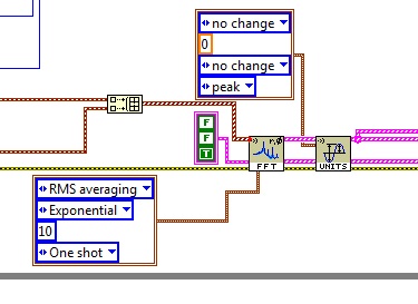
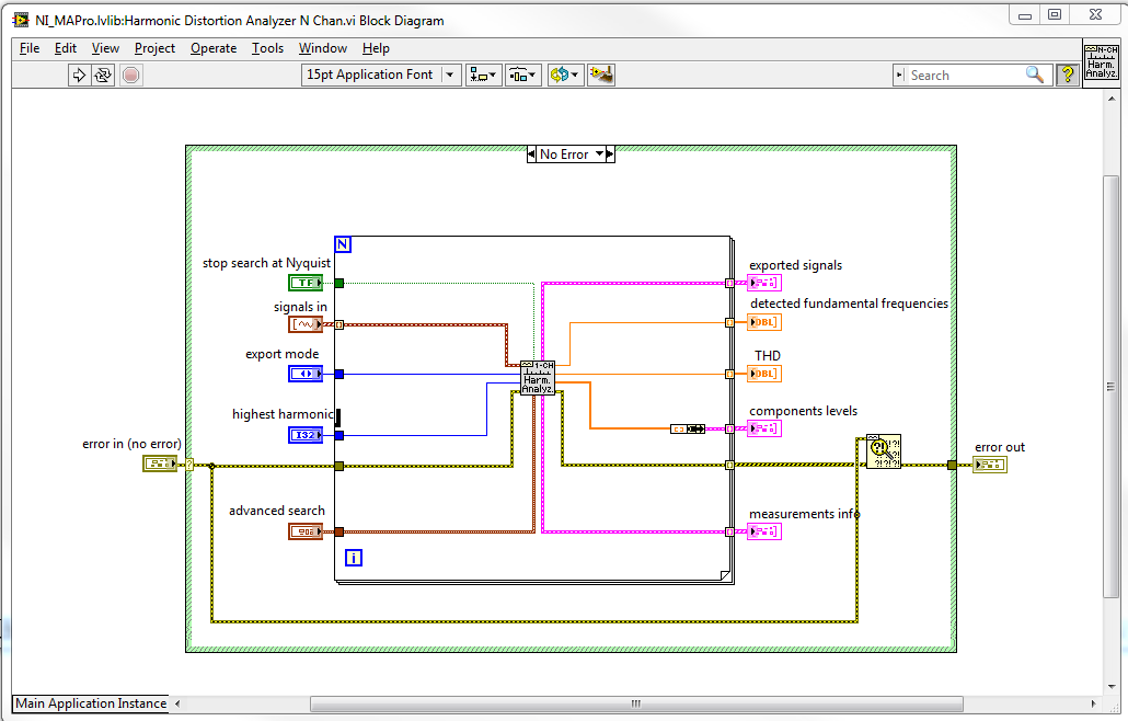
The VI I is not polymorphic, but you can easily change to work with multiple signals. If you look at the standard implementation for the harmonic distortion Analyzer N-channel then, he simply called the channel 1 harmonic distortion Analyzer a loop for. So you can easily call my VI in the same way. See attached screenshot:
Best regards
Anders Rohde
Technical sales engineer
National Instruments Denmark
-
Calculation of RMS through a rectangular window with gap of time 25%
Any signal (for example the sinuses), I need to calculate the RMS value, with an integration time of 1 millisecond , through a rectangular window, with a gap of 25%.
In other words, instead of calculate an RMS value by considering every 1 ms interval, I need to calculate the value of a 1 ms window, then apply a gap of time 25% (of the window) and calculate the next RMS value assuming a 1 ms interval and so on.For example, in a 1 ms window, there is a 75% overlay.
I appreciate all help.
Thank you in advance.
Hello.
It has been long since I last posted something.
I managed to get what I wanted, now I need to optimize it.
I simulate a sinusoidal signal and I get a 1 MS integration time 't' just setting the number of samples n and the "fs" sampling rate (fs = N / t <=>t = N / fs). Can I use the tool "Extract the Signal Portion" and I calculate the effective value of the part in a loop.
Anyone know if there is a way to do the same thing without the 'extracted signal part', because this tool using too much memory if the duration of the treatment is just too long with 4 k samples and 4 M samples/second.Thank you.

Maybe you are looking for
-
How can I access the internet with my Apple TV
Is it possible to access the Internet with my Apple TV which I can do with my laptop Smart TV and my Macbook Pro?
-
What is the best external display for use with Tecra A8?
It is perhaps off of a question, but I'm in the market for an external monitor for my Tecra A8. The price range of 400 euro round. Any suggestions?
-
Question again on the custom device. If there are 200 channels of output but every 100ms only 40 of them updated by the driver. Is it possible to write only the 40 channel data at the exit of the FIFO device at a time? What is the write FIFO RT speed
-
At the start of Hotmail, I had an email address that has been linked to an Email beta program @realbox.com which gave rise to a University. Since that they ending @realbox.com that I have been unable account recovery of access because the password sh
-
Updates to Windows on the Production servers
We have a requirement that RnD machines should not receive the patches once a user is working on it. The only option is to patch the data servers once the user connects or disconnects. The user must also permit/deny the installation of patches. I wou