Sawtooth analysis waves
Morning ~
I work on a project to read a variable entry Eddy current sensor and see it as a waveform. The profile of the spinning object that we are detecting is such that it creates a model of Sawtooth. What I am trying to accomplish with this is to create a specific drop point with a constant value that can be seen on the waveform. I need to be able to have this value remains the same at any RPM up to 60 RPM.
I can generate the front slope to a known specific window - but I can't understand how to add a constant value to the waveform instead of the drop.
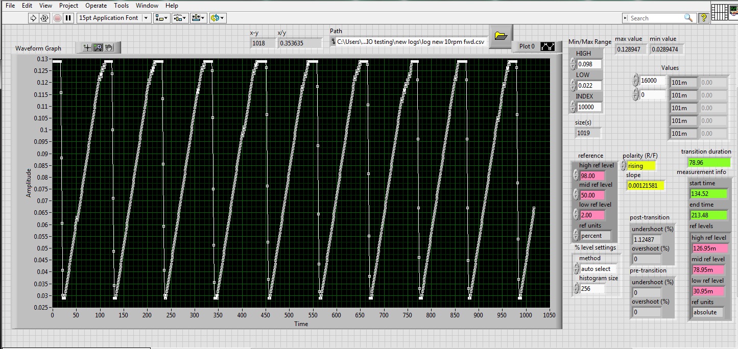
I understood the program and the actual files to play with them. It is important for me to be able to create this fall when the sensor indicates the point of fall with a known constant.
Any ideas?
It seems that this behavior is based on certain limitation of the used Eddy current sensor. Is the sampling probe too quickly to give a sense of the vertical face of the object scanned while the object runs at low speed?
If the behavior is acceptable at high RPM because the Eddy current sensor can take one or two readings of the rapid evolution of the vertical face?
Tags: NI Hardware
Similar Questions
-
How to tell the first does not scan waves plug-ins
Hello
How can I prevent the first analysis waves VST plugins. (Apparently vague is messing up with Red Giant Colorista II orders and those I need more then the waves in PP).Hi Sam,
In the Audio preferences, click the button to bring up the Audio Plugin Manager. You should be able to disable plug-ins.Thank you
Kevin
-
Hi, I'm having a little trouble with this VI that I'm working on and I hope that someone could help me. What I'm trying to do is to detect the two peaks of a wave pulse measurement file. Each pulse cycle has two summits, and I want to get the times of the peaks. I can get the first highest peak, but I can't seem to get the time for the second pic, you can see in table 2 waveform. It's the only thing that I get and I appreciate who can help me. Thank you.
-
Construction of a wave of fishing without Express/Signal Processing Pallete
EDIT: I forgot to attach the VI. I'll do it when I get home in 45 minutes
Hey guys,.
I'm working on a laboratory project that drives me crazy. We're building a VI that generates a sin, but we are not allowed to use the Express palette or sine wave functions. So we are stuck using tables and the Sin function. I have attached the VI if anyone can take a look. I would try to explain where he goes wrong, but... it's all so... One thing that I recently broke is the 'dynamic' wave is no longer scrolls to 10 Hz, but I think it's an easy fix. I hope someone can give me some pointers on what goes wrong.
Also, I have attached a copy of explicit assignment details in case you do not want to see them.
Display two sine waves on a single graph. Generate sine waves in a While loop that updates

at 10 Hz. At each iteration, the second wave should gradually phase shift by a certain

amount (degrees).

Have controls for frequency, the displayed number of periods, displayed points, phase shift, and

difference between display of waveforms. Make sure that the axis of the time-displays correct units. All the

controls must be active and adjustable, while the program is running.

Tip: You may find it useful to use a chart of waveform and the wave to build function.

Do not use the range screw Express for the manipulation of signals and signal analysis. Using more arrays
-
Measure the period and the peak value at crest of a sine wave
Hello
I am new to Veristand and Labview and I was wondering if there is the possibility to do the following:
I would like to measure the period of a sine wave that I capture from analog input of my data acquisition (SMU-6363). Apart from that, I also want to measure the value of crete to crete (Vpp) of the sine wave.
I hope you can help out me.
Thank you.
If the sine wave is of significantly higher frequency than the primary control loop can run... The best way to do it would be to put the DAQ hardware in waveform input mode and use a custom device to read the waveform and perform analyses.
an example is here: requires some labview skills
\examples\NI VeriStand\Custom analysis Devices\waveform -
Continuous data acquisition and real-time analysis
Hi all
It is a VI for the continuous acquisition of an ECG signal. As far as I understand that the analog read DAQmx VI must be placed inside a while loop so it can acquire the data permanently, I need perform filtering and analysis of the wave in real time. How I implemented the block schema means that data stays int the while loop, and AFAIK the data will be transferred on through the tunnels of data once the loop ends the execution, it clearly isn't real-time data processing.
The only way I can think to fixing this problem is by placing another loop that covers the screw scene filtering and using some sort of registeing shift to transmit the data in the second while loop. My question is whether or not it would introduce some sort of delay, and weather or not it would be supposed to be the treatment in real time. Wouldn't be better to place all the screws (aquicition and filtering) inside a while loop? or it is a bad programming practice. Other features I need to do is back up the data I na file, but only when the user wants to do.
Any advice would be appreciated.
You have two options:
- A. as you said, you can place the code inside your current while loop to perform the treatment. If you're smart, you won't need to put one another while loop inside your existing (nested loops). But it totally depends on the type of treatment that you do.
- B. create a second parallel loop to perform the treatment. This would be separate processes to ensure that the treatment is not obstacle to your purchase. For more information, see here .
Your choice really depends on the transformation that you plan to perform. If it's much the processor, this could introduce delays as you said.
I would recommend that you start at any place in the first loop and see if your DAQ buffer overruns (you can monitor the rear of the buffer during operation). If so, you should decouple the process in separate loops.
In what concerns or not ' it would be considered as real time processing ' is a trick question. Most of the people on these forums say that your system is NEVER in real time because you're using a desktop PC to perform processing (note: I guess it's the code that runs on a laptop or desktop?). It is not a deterministic systemand your data is already "old" by the time wherever he leaves your DAQ buffer. But the answer to your question really depends on how you define "real time processing". Many lay it will set as the treatment of 'live' data... but what is "actual data"?
-
Bode plotter and transient analysis
Hello
I'm trying to generate a sinusodial wave and amplify it. From what I've seen on the scope my circuit works fine, but the bode plotter and the transient analysis do not work for some reason any.
I have read some threads and guides online on without success...
Can someone please take a look at my drawings and show me how to connect the bode plotter and transient analysis tool?
Thank you
A
S.M.
To get the transient analysis of work either set initial conditions defined by the user, or to zero.
To get the Bode Plotter to work, you need to (temporarily) connect a voltage source to the point where you connect to the entrance.
See the attached file.
-
Is it possible to change the sine wave 'exit' a simulation device?
I work on a LV collection and analysis VI in LabView that interfaces with a CDAQ-9178 loaded with 9215 modules/a. chassis. In the Measurement & Automation Explorer, I was able to set up simulated devices that work with my code and I get the sinewave / 5 (?) standard signal noise %.
However, to really test my application, I need a slightly different sine wave with high frequency (1-10 Hz vs the)<1hz sent="" by="" the="" simulated="" device). ="" is="" there="" anyway="" to="" modify="" or="" get="" the="" simulated="" device="" to="" output="" a="" different="" wave? ="" if="" not, ="" are="" there="" any="" other="" simple="" ways="" to="" simulate="" the="" device? ="" i="" could="" write="" another="" vi="" to="" send="" out="" a="" sinewave="" but="" was="" looking="" for="" a="" more="" obvious="" or="" simpler="" solution="">
Thank you
# You need to do is call an of the generating functions of waveform instead of the DAQmx Read. Place inside a case, the declaration or the conditional structure disable is fairly simple.
-
Question of Gibbs phenomenon in square wave of labview builtin function generator
I have a server and a client, I send commands on my client's server to generate different signals. but the display of my square wave and a waveform sawtooth in the client a Spades and lots of harmonics to it. When compared with the display of the same waveform in my server, the square wave and sawtooth wave appears. Photo will show a comparison of the two.
Please help, I did some research and I think it could be the gibbs phenomenon happening and I'm not sure how to resolve this.
-
wave shot through of shunt dc motor
Hello
We have an application where the positive of a power source is connected to a shunt and the other end of the shunt is connected to the positive DC fan engine.
If a CRO is connected through the shunt, it shows a sine wave form. We want to replace this CRO with Labview software that allows to capture this waveform for analysis more away from ingredients using some materials preferably a USB based. We have labview 2009 version running on windows 7, 32 bit.
We are not sure if the material can be used since the motor is inductive and as soon as the power is turned on, it gives a peak. So we need assistance regarding if any material OR can be used directly in the system.
Thank you
Rohit
An important consideration is that these systems is the possibility of ground loops. The mass of the engine system and patterns of DAQ system can have enough impedance current heights in the engine, mainly because of defects, can cause enough voltage difference damage the measuring equipment or disrupt the measures.
Very rarely a direct connection to a shunt resistor is a good idea with loads of engine.
Consider using an isolated DAQ of entry device, an amplifier for instrumentation isolated between the valve and the data acquisition system or a single Hall effect current sensor. I used the devices of the series Allegro Microsystems ACS (> 2 kV isolation) on a few projects.
Lynn
-
I need to output a reverse sawtooth of an analogue channel of my DAQ. I tried to build one to simulate arbitrary signals Express but which generates dynamic data.
So, how can I make a dynamic data output and make it suitable to go to my DAQ card, or can anyone think how to reverse the wave sawtooth since the function generator, which generates a wave?
I tried the convert of DDT, but I still don't see anything on a waveform graph. I understand that Dynamic data has no timing information, correct?
I love when I have my own problems...
Thanks for letting me thinking out loud.
-
Hello

I got my microphone measurement in the PDM file, and now I have to load it into the other program and do a spectral analysis.
Program should be easy to build, I've done something, but when I try to run the program, it shows me error.
You can see what the problem is?
PS. I don't know how to choose from that to which the sample program to do analysis.
Sorry for my bad English.
Thank you very much
Jurij
You can attach files directly here. Just change the .tdms in .txt extension or add the .txt extension: ZSXD.tdms.txt
By getting rid of the Type of dynamic data (also called the Type of dynamic data wrong (DDT) by some experienced users of LV), you can use the functions of simple data manipulation to get what you want.
The attached VI shows a possibility. I replaced Express file VI close reading of measurement with TDMS Open, Read TDMS and TDMS functions. The Read function returns an array of signals rather than DDT. Your file onlyhas a waveform in the table. Inside the loop, I used Subset.vi of waveform get WDT to select a part of the wave. I replaced the Express VI spectral measures (and more DDT with .vi FFT (Mag Phase) spectrum) and the Express VI of statistics with RMS.vi and a few primitive. The structure of the event causes the while loop to go only when you change the index controls or press the Stop button. The timeout shift register allows the loop run only once at startup and after that only when a control is changed. Your original progam turns the loop as fast it can read the file, if something has changed or not.
Lynn
-
Sine, square and Sawtooth generation of sweep with variable duty cycle/rise time & descent
Dear all!
I ask and need some frank advice on the question of the subject counts with the following note:
(1) I am a novice in LabView.
(2) I graduated in electronic engineering average who graduated about 9 years ago and since then I have not been involved in electronic engineering.
I have undertaken a task or the generation of sinusoidal waveforms, Square and sawtooth. All these signals must be swept frequency form 1 Hz to 100 kHz. The amplitude of these waveforms should be able to be adjusted. The Square Wave cycle should also be adjustable (or better to be able to be scanned). Similarly the rise time and the fall of saw teeth time should also be adjustable (or better to be able to be scanned).
Is considering other options as well, I want to try it on LabView.
I would like to ask that is it possible to perform this task in Labview 7.0? If possible given the para 1 & 2 above, is it possible for me to finish this task in 15-20 days if I work on it for about 3 hours a day? If this isn't the case, then that may be a reasonable estimate?
I'll be very grateful if you people can offer advice on the whole project or part of it.
Thanking you in advance and requires urgent response (s).
If you have less than the full version of LabVIEW, you have defined functions of generation of waveforms. They can be used to generate the signals of Zack with the NI DAQ board. An experienced programmer may be able to write the program in as little as 3 hours in total. How long it wouldw take you is going to be a little higher but depends on how long you are willing to invest in learning the basics of everything first.
-
How to generate a sine wave of table of values?
I have an array of points (values) around 1000. I want to draw them in different types of waveforms - triangle, sine, cosine, etc..
How ca I do that? For the waveform of triangle, I was able to split my table into 2 halves equal and draw the first half and the separately half second to generate a waveform of the triangle. But how to sine, cosine, Sawtooth etc.? It is a matter of urgency. Prompt response will be appreciated. Thank you
Hello
The VI in math palette is a polymorphic, it accepts the input also array.
attached a VI for your reference.
VI generates 1000 randon numbers and trace the sine and cosine wave.
-
SLIDER FOR WAVES IN MASTER VOLUME MUTES AUTOMATICALLY
Hello Sir/mam,.
The wave slider is muted after a period of 5 minutes. More emphasis moves in the current window regularly i.e., as and when I type in a browser, the focus moves to nowhere and I have to click anywhere inside the browser to continue. Does analysis antivirus but shows no virus. I went into the Task Manager to see if there are any suspicious process. I saw IEXPLORE. EXE in capital LETTERS that runs even if internet Explorer does not work. I guess that this process is the reason for my problem. Any suggestions on how to eradicate it, or any other suggestions welcome.
Hello
If this is caused by a malicious software then the methods above including RootKits should delete it all.
If you need Trojan Remover (which I have not tried so cannot recommend)
Trojan Remover 6.8.2 or later version
http://www.simplysup.com/and never checked it:
Bootkit Remover
http://www.esagelab.com/resources.php?s=bootkit_removerFrankly, I have much more confidence in Bootkit tools previously linked to above.
Rob Brown - MS MVP - Windows Desktop Experience: Bike - Mark Twain said it right.
Maybe you are looking for
-
Change of name on the iPod Nano 6th generation
I bought an iPod Nano to its original owner, and it shows his name. How can I change my AirBook Pro?
-
Where can I find the Multipoint server 2010 and 2011 Dutch languagepack?There is a pack of 35 languages available, where can I find it? Thank you
-
Original title: 0701 start error comes every time how can stop
-
Specifications required for the replacement of a hard drive
Hello I have a Presario CQ60 laptop 212em. If I had to replace my hard drive and could not get a replacement of original HP for my computer, what are the elements of the specification would I need to know when looking for a new from another manufactu
-
Hi, friends I need some ideas on this issue, when I take a picture I need to reduce the quality of this image for example to 75% of the suggestions