sbRIO-9626 driver
Hello world
I want to simulate my program on the host PC before buying the sbRIO-9626, in order to be sure of sufficient space on the FPGA necessary for my program.
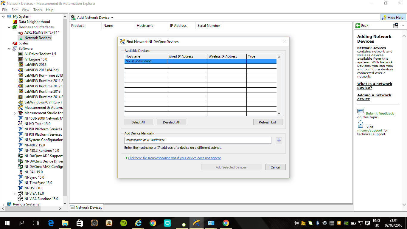
But when I want to create a new FPGA VI under 'My Computer', first of all, there is no "... target and devices" in the menu bar 'New' (image) below:
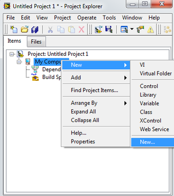
Then after selecting New... Windows appear:
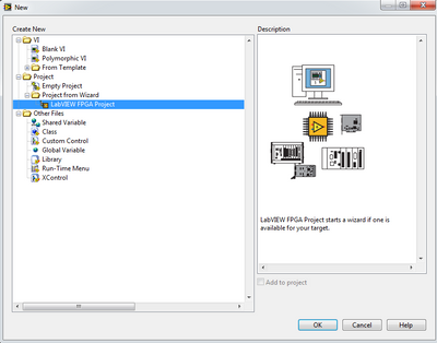
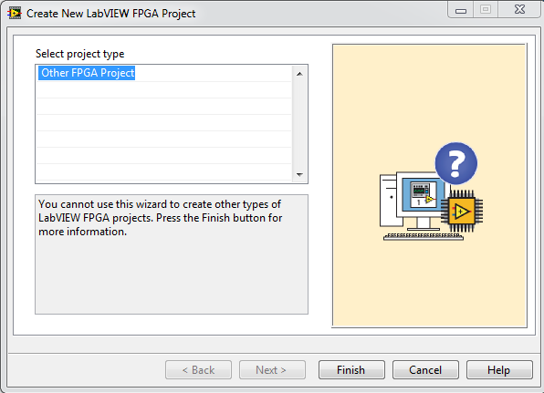
But I can't create a new FPGA VI. I guess that the source of the problem is that I do not install the driver for this card, I'm good?
If so, please would you give me the driver of the sbRIO-9626? (I tried to download the driver from http://www.ni.com/download/ni-rio-12.1/3769/en/ but it is almost 2.5 GB, which I suppose is for all cards OR, y at - it a smaller pilot for only this Board?)
Thanks in advance
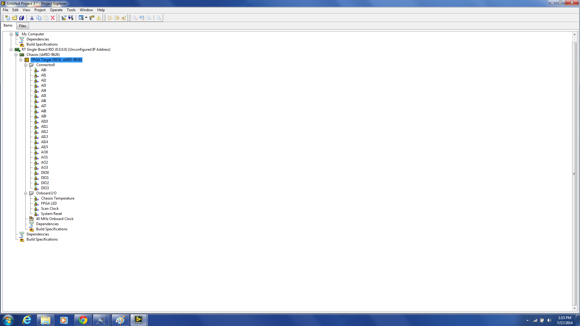
I installed the Driver NI 2013. The problem is resolved.
Tags: NI Hardware
Similar Questions
-
Lack of Ports on the model of project sbRIO 9626
Hello
I'm working on the development of FPGA software for the sbRIO 9626. Unfortunately when I create an empty project with the wizard, I get only Connector0 without Connector1 or Mezzanine ports. It seems that something might be wrong with my assistant. Can someone give me some advice on how to fix this? I need to access those other 100 IO or more.
Thank you
Zach
You must add a Mezzanine of RIO to the target FPGA to expose the IO CTMR. Right-click on the FPGA target and select new > CMR (or similar, I do not have LabVIEW in front of me). In the follow-up dialog box, you can select evasion DIO 9694 CTMR to expose all the I/o, or I think there is an option for RMC custom which also exposes all the OID.
Connector 1 is not available/populated on the sbRIO-9626. These DIO lines on connector 1 to the sbRIO-9636 pass alternately to the CMR.
Kind regards
-
Share data between a PC host and NEITHER sbRIO-9626 connected by Ethernet
Hi Sophiec,
In fact, shared Variables are a good way to share data between a host and a target. However, this is not the only way for data sharing.
On the follow-up document, you will find different ways to do it: http://digital.ni.com/public.nsf/allkb/48D244EC86971D3986256BD4005CCC28 as:
Shared variables
TCP
UDP
DataSocket
Other methods of CommunicationI hope this will help!
-
NOR-auth sbRIO does not produce prompt does not
I have produced a Web service that runs on the server of web applications on a device sbRIO-9626.
However, I have problems of securing access to it with the standard tools of NOR-Auth.
I created a user and permissions according to the guide (for PC webservice):
http://digital.NI.com/public.nsf/allkb/DF41D5DA8EEB4840862577D90058C208
However in step 20, when I try to access a secure, http method I do not get a login screen OR-Auth, with possibility to enter user name & password, but just a "400 - Bad request error".
He works if I access the method via the page of Web services on the web to device configuration screen (the silverlight page), with credentials username & password added in the "Advanced" tab
Why the NO-Auth login prompt is not be generated on my PC remotely?
Thank you
This problem was solved by the formatting of the sbRIO and re - install software on the sbRIO sbRIO components.
This also solved another problem where web services would work when published as services web application, but refused to work when it is deployed as web services embedded.
Bravo to me bravohelen:
-
SBRIO DIO still available with 9693 mezzanine card?
Hello!
I intend to use a SBRIO (9626) and a map of mezzanine 9693 for plugging a 9853E module CAN.
However, I would also need interfacing #20 DIO, 4AI and 4AO. The signals will be be wired on J502 and J503 connectors.
Using 9693 mezzanine card, always will I be able to get/check status of DIOs/AIOs using the FPGA?
Hi zyl7,
The NOR sbRIO-9626 has only 4 asymmetrical on the J503 connector DIO lines as the sbRIO-9626 isn't a J502 connector. Using the 9693 OR prevents access to the CMR for anything other than the two C series connectors.
The J503 connector has 16 HAVE and AO 4 so that will work best for your needs that you can access IDC connectors and RMC connector at the same time in LabVIEW.
The isue with the sbRIO-9626 and the 9693 OR in your application, is that you will only access the DIO 4. If you need 20 DIO, you probably a DIO module in the second location of the 9693 OR add at least 16 DIO for your application. You can then use the 4 DIO embarked on the connector J503 IDC and the DIO on the C Series module to meet the needs of your application.
You could also add support on your daughter card circuits to multiplex your DIO 20 up to 4 lines DIO the sbRIO-9626 puts at your disposal. That depends entirely on the requirements of DIO, however.
-
iHi.
My apologies if this is the wrong Board... not sure where it should go! Just to clarify from the outset, I cannot share screws due to issues of IP etc... sigh.
Basically I have a sbRio 9626 and the software that runs on the FPGA to interface with analog converters / digital external. This is done using a machine to States (single cycle loop timed with a structure of business inside, so it passes between cases each tick of the clock FPGA). In one of the cases (the States), I have a little routine that takes data from the ADC and place it in a buffer FIFO of DMA of target-to-host. In fact, there are 4 FIFO DMA buffers to send various information and the value of the sample. It is then read by the software on the host of RT and processed to produce an array of values which I then send to the PC using a shared variable.
What I wanted to check, is that data sent from FPGA to RT host (and PC) are contiguous (that is, I have my right to lengths FIFO). I modified the code FPGA to use a counter instead of the data sampled for the FIFO must simply send numbers in a sequence (1, 2, 3, 4, etc.). I then examine this sequence to ensure that it is correct, and no data has been overwritten.
I think it's the FIFOs, 2, 3 and 4 are very good. FIFO 1 sends data that is continuous but every now and then I seem to get a glitch at random. This glitch is * not * appear to be due to lengths of FIFO, but seems to be an error in the data transfer. For example, I get something like 1, 2, 3, x, 5, 6, 7, y with x and y the seemingly random values. The positions x and y in the sequence are also seemingly random - they have not held in the same place every time. Code written to the FIFO 1 is * exactly * the same thing others - in fact, it's the same group of data being written.
Has anyone seen anything like this before? I am trying to determine if it is due to the goal to receive FIFO or some problem with the shared variable in the network. Any suggestions as to what I could check? It almost seems as if there is IME peaks on the transfer... does not suggest this is the case but it gives an idea of what I see. I'm using Labview 2013 and BIOS on the sbRio is up-to-date. I have sbRio another I'll try again later to see if the problem is specific to a particular board.
It seems that you have found the wrong path here: since you are dealing with the programming of FPGA, which is essentially played woth LabVIEW you should post this question to the Office of LabVIEW or, perhaps, to the Office LabVIEW Embedded
-
Connect the sbRIO amulet monitor
I have programmed my amulet display and have a VI RT on my 9636 sbRIO which must communicate with the amulet. I have the amulet the sbRIO-related uses the USB port. I also installed the software on my sbRIO:
(1) NI-VISA 15.0.0
(2) passport OR VISA-USB 15.0.0
When I run the RT.VI, it is not the USB port on the sbRIO. I guess I'm missing some software on the sbRIO but can not understand.
Thank you
Craig,
To dispel confusion, you shouldn't see your amulet device in MAX, you should see the sbRIO. In addition, you cannot communicate via USB between the sbRIO and amulet device, but you can communicate over the serial (RS232).
You are right in saying that you are missing on the sbRIO software because there is not a driver for the sbRIO use USB.
-
I couldn't plug sbrio-6932 Max or using ethernet
the use of lab view 2013 or visa 1.5 drivers 2015
the ethernet is connected to the chip
The sbRIO is a computer, it will appear under systems remote NI MAX and not network devices. It also uses the RIO driver and not the pilot VISA, so you probably need to install who, before appearing in MAX OR.
-
store data in external storage with sbRIO 9602
Hi all
Does anyone have experience of sbRIO data storage in an external USB or any other type of storage?
Since there is no USB port on 9602, I am planing to use for serial ports do.
But how?
Thank you.
Zhuoyuan
Hi Zhouyuan,
This wikipedia article on the technical details of SD card is where I got the idea of using the FPGA to speak directly to an SD via SPI.
http://en.Wikipedia.org/wiki/Secure_Digital#Technical_details
Unfortunately, I don't know all the technical details that would be involved to make this work, but it seems possible.
As I said, the SPI interface for SD cards is very low, and develop a functional driver can be difficult.
In the spirit of brainstorming of ideas... You could create a small logging system compatible ethernet on Arduino. I searched a bit on Google and found the shield which includes the Ethernet and SD card. Coupled with the Arduino microcontroller, the device could receive the news of the IMU of sbRIO via ethernet on the robot and save the data on the SD card.
Both the aforementioned efforts would work, but are less expensive than adding a dedicated SD card module that includes the necessary firmware in its design.
See you soon,.
-
Someone has a vi for LCD with port COM for SBRIO
Hi people,
I have a SBRio-Board and you want to drive a LCD on the COM-port.
Is this possible?
Someone has a vi to do this.
I know, it's possible with FPGA lines, but is not the normal/best way COM port?
Greetings, Ruedi
If you look on the LabVIEW tools network and search for LCD a few possibilities appear. http://www.ni.com/np/app/main/p/bot/no/ap/lvtn/lang/en/pg/1/sn/n25:software, n21:28/sb/default /? q = LCD
It is said expressly in the box to Reach tools that it is via RS - 232 interface. Although not your specific device would it be worth the trip.
Its interesting that I would have liked to have a few years on a project using a touch screen of Reach.
There is also an example here http://www.ni.com/example/31079/en/.
I hope that this will help.
Warrior of wire
-
Attempt to add a "new target or device', but the sbRIO 9607 is not listed
Hello
Just upgraded to 2015 LabVIEW and CompactRIO 15.0.
Also used the Service to update OR install the patches for 2015 of LabVIEW and CompactRIO device drivers.
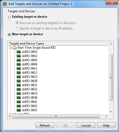
I'm trying to add a target in LabVIEW in the window "add targets and devices." I select 'new target or device' and develop the sbRIO options. I see a lot of targets, but unfortunately the sbRIO-9607 does not appear. It simply isn't.
Thoughts? When I'm back in the office on Monday, I'll try a repair of the driver.
Best,
Dan
Well, this is embarrassing, but I don't know I'm not the first and won't be the last to commit this error.
I had accidentally opened LabVIEW 2014 SP1 instead of 2015 of LabVIEW.
Of course, it works in 2015 from LabVIEW. Congratulations if you guessed this might be the problem.
-
Hello
I'm working on Dani 1.1 robot with sbRIO. How can I add/connect another sensor it and test it. Its a sensor to ultrasound (LV - EZ1 maxsonar).
Help, please.
ConcerningHi Danish666,
What kind of bus the ultrasonic sensor work by?
The sbRIO using, there are options of communication via protocols such as wireless. If the sensor uses TCP/IP or UDP to send and receive data, then it should be possible to write a driver for LabVIEW RT to talk to the probe. The complexity and involved, this driver may need to be will depend on the sensor.
As the sbRIO works on real, should also check the compatibility between the sbRIO and time any sensor that you are wanting to plug in as drivers may have been designed for a windows OS. If it is compatible, then we can discover options such as communication to him through VISA controls.
I look forward to hear your responses.
Kind regards
-
Strange behavior of pines sbRIO DIO
Hello
I use a SHT7X temperature/humidity sensor which gives the digital output. The sensor has two digital lines, clock line and line data. The data line is bidirectional. A pull upward resistance 10 kohm through the data pin is used to excite the high data (voltage level = 3, 3V). The sensor works on an I2C (sort of) Protocol.
The digital pin (in this case the data PIN) drops sbRIO-9633 "bass" when a high is sent through the program and remains "high" (due to the lift) when a 'hollow' is sent to the PIN in the program. What is the explanation? What happens when a PIN is already high (in reason to pull it upward) and the user also sends a top to it?
If it falls to zero? Why?
Note: In the program FPGA, the data pin is configured accordingly. In other words, the output (enable and disable) parameter is set up according to its bidirectionnalite operation.
kdm7,
I can't answer with 100% confidence that your code snippet is out of context, but yes, it seems that you should swap the case of the structure of the case. (The true case should write 'F' Set out allow and the Fals case should write "T" Set out allow).
In addition, it is probably not necessary to repeatedly write 'F' to DIO26. Once you write 'F' DIO26 once, logic will persist until you write to DIO26 once again, no matter what happens outside on the line, DIO and determine if the output driver is enabled or disabled.
You must also understand that by using the node IO FPGA to write 'F' to DIO26 time written 'F' and allows the output. If you want to separate the Act of writing the value of the output, then you must use the method "Set the output data" to write to the DIO line without impact on the output enable.
If you notice in the preceding two paragraphs, you can eliminate the structure case completely and just write inverted logic to "Activate the Set output" rather than having the two cases of additional logic. You just initialize the DIO data false line before arriving at your logic.
This page of the help of LabVIEW has the best game of documentation that explains how the FPGA DIO nodes work compared to methods "Activate the Set output" and "define the output data:
-
E/s and the issue of Communication for the sbRIO-9601
Hello
Our company is looking to use the sbRIO-9601 in an OEM application and I had two technical questions on the Board of Directors.
(1) are the functions VISA support? I saw there an RS232 port, I want to just make sure I can read/write easily out of it using prebuilt VI rather than do all the level low and starting from scratch.
(2) we will be reading and writing of simple commands to a device coupled via the RS232 interface and based on the response, illuminating an LED controlled by the Board of Directors. I have not selected any led and hoped that neither could provide some clarification on the limits of the power provided in the sbRIO-9601 user guide. We will use the 3.3V output... I should put a resistor in line current limiting or I can put the diode directly between the output pin and the digital ground? Us can drive more than 15 LEDs, however, we will never more than 3 see on at any given time. I saw in the 3.3V section i/o of the documentation that the current max tested per channel is 3mA... but bus total is 330mA. Is there a limit to how much we can provide each channel as long as we remain under the 330mA all together?
Thank you
Hi leachdor,
(1) VISA functions are supported for the RS232 port on the sbRIO, so do not do any level low programming for them.
(2) the maximum that we specify channel 3 is my. You can combine several channels in parallel to increase this output up to 330 mA for the total bus. Since you're only driving 15 LEDs and there are 110 channels of output, you should be able to combine some led.
-
Moving the sbrio 9606 FLASH files
I'm trying to move files in main memory or flash my sbRIO. I followed the example in this link just to find out where c: / is written in too. It turns out that I can write only to c:\ni-rt\ and that works (c:\ does not seem to work). I am able to ftp by opening a Windows Explorer and tpying in ftp://adresseIP and see the file. I guess I can use a FTP tool like filezilla to move my files in this site under my own directory and work with them. This is to support the hexagonal flashing device and start with the files.
But how you search for a file on the flash drive? I saw a reference to d: /, but what is the ftp://adresseIP?
I don't know there is a documentation on what I can't find it.
Thank you
-SS
Hi Simon, shooting
You try to access a plug in USB Flash drive plugged into the USB port of the sbRIO-9606 via the FTP client? It is possible and is documented here: using FTP to access and use the external CompactFlash or USB on a real-time controller
CompactFlash drives (if any) should indexes to drive D:\ letter and USB readers must index starting with the letter of player U:\
If the documentation above is not what you are looking for, then I'm not sure what you're trying to do, or where you have a problem. An FTP client must be able to navigate to files on the file system of RT, including something like Filezilla, Windows Explorer, the FTP client included in Measurement & Automation Explorer.
See you soon,.
Maybe you are looking for
-
Move a message from Inbox to the model
How can I move a mailbox to a folder in model
-
Kind of hard to explain in the title... who probably is meaningless. Basically, I used to use a BTinternet email for any account. But over the years, I went to my iCloud email account. I have both implemented in mail because I still have the BTintern
-
I want to go back to version 20. How. I hate the stuff of yahoo. Mac
I am Mac 10.6.8 and want just my old browser back which was not related to yahoo. Yahoo has encouraged me to get 21 but I don't want to. How can I get 20 unrelated to yahoo in return.
-
Panic userspace, can not log in to the system!
It is the question of the panic of the user space. So I can not connect to the system. is it still possible to recover my files and data in the SSD?
-
O.P. Hello. Try to establish if the optical SATA connection on an iMac in early 2009 will achieve 2 SATA speed of 3 GB with a 500 GB SSD crucial MX200. Have already tried a Sandisk ultra 2 with controller Marvell and only got a negotiated speed of SA