scale daqmx
Hello
I have a (probably stupid!) question: I am acquiring data with a PCI-6281. I want to measure is a tension in the scale of the nV. But if my values are larger than 10nV, my software does not record the correct value. I know that the for my card is between-10 and 10V. So, how can I change the scale to record larger than 10nV values correctly?
Here's my simple BT 8.2 software.
Thanks for your help!
Sophie
PS: I am acquiring data at 300 kHz and I need to acquire for 1 min. If I save the values in several files in order to be able to do the analysis after registration. If I want to save to a file, this one is too big and LV blocks... If you have any suggestions, I'm open!
Hello
1. the datasheet of the PCI-6281 RPF said valid voltage ranges: ± 10 V, ± 5 V ± 2 V ± 1 V, ±0, 5 V, ± 0.2 V, ± 0.1 V, so adjust the 'minimum' and 'maximum' of 'DAQmx create Virtual Channel.vi' ± 0.1 V for the highest precision.
2. your losing data on the 'picture to a worksheet string' work, because you are fit only with "%.3f. Save the data in binary form DBL-table 2D and convert the string representation when analysing data in mode offline, but with more significant digits, for example "%.6e". This will also increase the performance of data acquisition.
3. you must separate the hardware DAQ from the part of the file-IO. In your VI the DAQ has to wait for the file-IO ends before getting the next data samples. During this time you will acquire all the data. Take a look at the design of producer/consumer model (file-> New-> VI-> model-> Frameworks\Design Patterns).
4. for file names, you can consider using a name that contains the date and time. Try the "Date/time Format string" to use "Data_%Y-%m-%d_%H-%M-%S.dat" as the format specifier. Then, you won't need to check if the file already exists. It will also increase performance.
Tags: NI Software
Similar Questions
-
Control of data rows Excel (write on a file of measure)
Hi all
Objective:
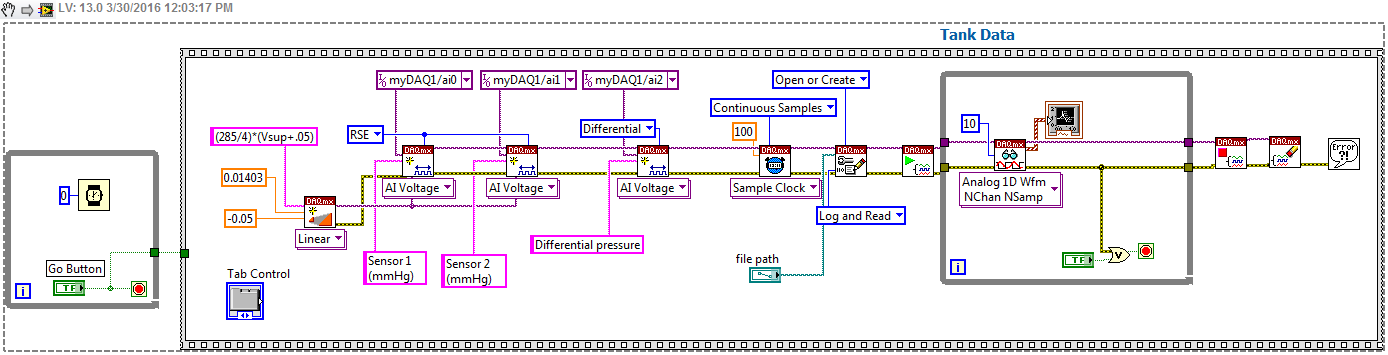
Get a bit of a live waveform of two pressure sensors, as well as calculate the differential pressure. The LabVIEW VI is intended for students for an exercise in module, in which data are exported to an excel file for the students to perform other calculations. Excel file must contain data from the beginning to the end of a race.
Problem:
Pressure sensors work well, waveform table works well, but when you stop the collection of data, the amount of lines in the file Excel output will reflect the number of samples per channel of the DAQmx Read Block (10 = 10 rows of data, 100 = 100 lines, etc.).
I would appreciate some advice on how to conduct the data collection in the part worksheet from start to finish, without this affecting the aesthetic experience of the student (by that I mean the number of channels of the > 10 sample will cause some lag in the waveform, jerky). I tried to resolve this issue with something in the sense of Tank1Solution.png without success. I've included a photo of the original block (Tank2Block.png) and so I worked the file VI. Once more, any help would be much appreciated, I'm not well versed in LabVIEW and I do not know how to address this problem effectively.
Some guys are always doing things the hard way

Of course, you need a son to ai0 - ai2 and ai1 - ai9. This linear scale DAQmx is of course very convenient! and hey, the TDMS files import beautifully into Excel! the addon is there then why not just open a session data? TDMS is much more portable than xlsx.
A few additional remarks. (a) you can't stop this vi before you press Go-who needs a fix. (b) Create scale is likely to return an error as it is the name being illegal. I named it that to show the source of the scale and offset values.
-
How to use DAQmx create linear scale
Hello. I have an output of an amplifier which is 10 mV/V, which is read by a USB-6002. This amplifier voltage range is 0 to 200 volts. Have tested the DAQmx create scale Vi, I don't understand how it works. Looked at the other posts here for answers, I still haven't understood how it works. As a first step, it says that it uses the y = mx + b equation for it. I don't know what the slope refers to except if it is the angle of the line. If someone would have an example that explains how it works, it would be great. I also tried to look at an example but could not find one. Thank you
Here is an explanation "improvised" y = mx + b. If you think of 'x' as the input and 'y' as output, then you can consider "m" as the gain, and "b" corresponds to the offset, the output that you can read with zero entry.
If you think of this equation from an amplifier, many are designed to have zero output when there is no entry. In other words, b = 0. If you have a gain of 10 mV/V (which I guess means that a 1V input would give an output 10mV, then m, usually called "the slope" (which is the slope of the curve of output), serait.010/1 = 0.01.)
Note you describe the range of the amplifier as 0-200V, so the output will be 0 - 2V, well inside the ±10V USB-6002.
Bob Schor
-
Scaling inside LabVIEW DaqMX task is not being to scale correctly
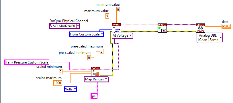
I'm reading from a physical channel, scaling of this reading and an indicator on the output screen.
If I do not fit the channel it will output 3.07 volts (This displays the same Max). Consider the following code. Physically, I use a 1000 psi pressure transducer which outputs 0-5 volts.
If you do the math I should show approximately 600 lb/po2. The problem is, with the scale it shows me 10.54.
Any ideas?
Your Max and Min on your channel to create DAQmx should be based on reading AFTER application of the scale. This is why you must set your max 1000.
-
DAQmx custom scale: How do you define minimum and MAXIMUM values?
Hello everyone,
I am currently using LabVIEW 2010 and meet the following problem with DAQmx custom scale: first, I created a custom linear scale (ordered originally = 0, slope = 50) and then a string that uses this scale. The real signal acquired from a NOR-9205 (module I) is in the order of-8 / + 8 Volts; When I try to read the measurement of the chain, it seems saturated.
I discovered that the change HAVE. Max and the AI. Min by a DAQmx channel property node I can improve the situation, but the fact is: I was not able to define a range of-1000 / + 1000 for instance because it exceeds the maximum allowed, and I get an error!
So, it is the custom to scale?
No one knows how to fix?
It seems not to be any possibility of having a large scale factor! If I want to convert 1V 1000V I will never reach it!
Thank you much for the help.
B.
Hello
The custom scale will be the function that converts the voltage to some units, you can. If you use a linear scale, it is in the form:
Data units user = m * wine + b
where m is the slope and b is the intercept at the origin wine is what happens to the analog input channel.
The MIN and MAX define you are the min and min AFTER the scaling. So if you want 1 volt in Ain channel to appear as 1000 in the code, you:
m = 1000, b = 0
Then your MAX and MIN is limited to-10000 and 10000 when DID channel lies between +-10V. By selecting a MAX or MIN outside this range will cause an error and numbers read apart from this will be so much saturation.
9205 a selectable ranges: ±200 mV, ± 1, ± 5 and ±10 V programmable input ranges. I haven't used the 9205 so I don't know if this range is automatically selected or the user defined in the module preferences. Whatever it is, it will have a possible effect that MAX and MIN are.
For example.
If you did what you said and used slope = 50 and intercept = 0 AND you got the system set to ±10 volts, while the MAXIMUM and minimum that you can set are limited to ±50 * 10 = ±500. So if you try to put a maximum of 1000 in there, you will get an error because it needs to be at + 500 to-500. Your saturation occur at ±10 volts (what is scale ±500)
If the interval is set to +-1 volt, your MAX and MIN should be within-50 to + 50. All values apart from this will produce errors. and if you try to read voltages above + 1 volt (+-50 scaling), there will be saturation.
I hope it is clear and useful.
-Alex-
-
DAQmx read - the values on the scale or not? Binary conversion.
Hey everybody,
I had a question regarding making the scale and the release of Renault. I use LabVIEW 2009 SP1, with a pilot DAQmx 9.0.2 and a X-Series card. I'm reading the data my DAQ and store it in a binary file.
How is the acquisition of data read samples, in General? that is if I select NSamp NChan I16 2D Analog on my DAQmx Read, what kind of values can I expect if I was at the exit of the probe data? (Suppose I have readings in mV values and my overall fork's 04:55 V.) When he wrote in the binary file, what happens, what can I expect to see in terms of values - or maybe just descriptively?
Overall, a little insight would be very helpful. I tried to troubleshoot asymmetric readings I received, so this will help me immensely.
Thank you.
Hi Matt87,
Reading data as I16 will return the result adjusted, not calibrated for 16-bit ADC.
If you want to write your own binaries, you'll want to include scaling of device - for series X, coefficients a 3rd order polynomial.
Here are two examples that show how write to a binary file and read the data back. In this example, scaling coefficients are stored in the file header:
Continuous gain and voltage drop (binary) chart
Graph of the acquired binary data
That said, I would recommend that you look in the record feature integrated TDMS introduced in DAQmx 9.0. The result is a file appropriate binary .tdms which is a standard format that can be opened in LabVIEW or in several other programs with the plugin. See the following examples for how to use the function:
Streaming data and log to the PDM file
Continuously to log in a PDM file data
The second example does not force you to read the data in the memory of LabVIEW and use the minimum CPU. The first example allows you to see the data that is acquired.
Best regards
-
TDMS properties show polynom scale even if DAQmx ist to linear bracts
I aquire data with DAQmx and write the data to a PDM file. The input channel is updated with the linear scale, as shown in the 'Code Skalierung' image. Unlike this linear scale of the channel-properties file TDMS show a scale polynom with totally different values.
How do I adapt my HAVE linear and the properties display the appropriate scale values?
To add information to Andy, many devices require a polynomial scale is because the analog-to-digital converter (ADC) on the device has non-linearity at the top and bottom of the range ends. A linear scaling of the raw data would not account for these non linearity, which is their precision and very high and very low readings. So instead, we use a polynomial scale that reflects much better the actual physical properties of the device.
-
Creation of several DAQmx scales for the axes of accelerometer
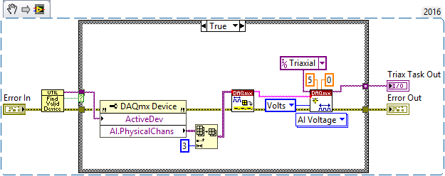
I'm having a problem programmatically create customized for analog input with DAQmx scales. Here's the background. We are trying to develop a small Triaxial sensor for monitoring the twitching (it's a student project, I'm an "Advisor"). We have a Triaxial accelerometer that puts off voltage proportional to the components X, Y and Z of acceleration. The accelerometer works a 5v power supply, each channel being a 1.5 v (offset) bias and a gain of 0.3 v / g, with a 10% of variability of these parameters (e.g. gain varies between 0.27 and 0.33 v/g).
One can easily read the three channels of acceleration with an NI USB-6009. "Proof of Concept" originally, we were easily able to measure muscle tremors, but noted that the channels were certainly not calibrated.
I designed a calibration procedure which was fast, reliable and reproducible, requiring that the X, Y, Z tension measurement when the accelerometer was held at six direction without moving - the whole process takes 15 seconds. But then, I decided to 'smart' (always a bad sign).
I have never used custom DAQmx scales, but thought "why not use the values of calibration for the axes X, Y and Z to programmatically set custom for the three areas so all scales is in units of"g"and centered around 0 g". I've defined a "Triax" task in my project - if I manually entered the scaling factors deduced my calibration, axes read all between + 1 and -1 g (depending on orientation) then the sensor was motionless.
But I can't figure out how to take the calibration data and assign programmatically to each channel its own custom scale.
Here's some code. This first Routine detects the Triax task stored in the project and ensures that the correct USB-6009 case is connected. In its project work, I appointed the three channels physical ai0 ai1 and ai2 to X, Y, and Z, and together the voltage between 0 and 5 v - this code basically resets the scale for these three channels. It seems to work correctly.
The reason I do it is that I want to record these three channels using the standard Volt scale, I will use these tensions to run the Calibration procedure I developed to get through three and get the necessary parameters to the custom scale.
Here's what I tried to create a customized channel X, Y and Z (the scales are named X_Scale, Y_Scale and Z_Scale). I tried a number of things, it's just one of them, but I did have a success to get anything to work (to talk to avoid the errors of DAQmx). Either way, if I get the scale factors 'manually', my accelerometer readings are, indeed, optimized between-1 and + 1 g.
Some of this code may seem too complicated - do - me confidence, I tried to make it more simple, but there are all kinds of 'hidden hunting for witches' in some of these functions that "made me do it" this way. But, of course, this does not work.
Ideas and suggestions are welcome! I will continue to work on it, of course (but, thankfully, I did not the device at home with me, if I get a little break...).
"Puzzled" Bob Schor
-
Full scale PXI - 6254 DAQmx Analog Input
Hello
I use PXI - 6254 Board to read the analog inputs. Configured channels using DAQmx create Channel.vi with sub parameters.
In the configuration: CSR
Min: 0
Max: 10
Units: Volt
I read the channel using DAQmx Read U16 2D with the sample of 1. I expected below the values.
data of 0 v = 0
10 volts = 65535 data
but it gives 10 volts = 31544 data. Please let me know why.
If I set up the channels with the settings below:
In the configuration: CSR
Min:-10
Max: 10
Units: Volt
He always reads the same values (data 0 v = 0, 10 volts = 31544).
Please let me know, how I can get 10 volts = 65535
Thank you
Hi LVTestek,
The PXI-6254 is not an interval 0 to 10 V input V. The specification of 625 x OR lists the available input ranges:
Entry level of ± 10 V, ± 5 V, ±2 V, ± 1 V, ±0, 5 V, ±0, 2 V, ±0, 1 V...
When you set Min = Max 0 = 10, DAQmx chooses the smaller input range that allows to measure signals between 0 V and 10 V without clipping. On the PXI-6254, the smaller input range that meets this criterion is the range of ± 10 V, where - 10 V corresponds to-32768 0 V corresponds to 0 and 10 V corresponds to 32767.
However, there is an additional complication: ranges entry on M Series devices are slightly wider to accommodate the software calibration. Otherwise, gain of a device could reduce the scope of actual entry, and offset error would move the ends of the effective input range. If the [-10 V...] 10 v] range on your PXI-6254 could be more like [-10.3 V...] 10.4 V]. 10 V is actually to 31544, rather than 32767. On another PXI-6254, 10 V could correspond to a different value of gross / scaleless and 31539 31552.
Another side effect of calibration of the software, is that the data returned by the flavours 'raw' and 'no' to the VI DAQmx Read are benchmarked. The KB explains further: is raw data DAQmx calibrated or chipped?
If you can modify your application to use one of the flavors "on the scale" (F64) VI DAQmx read, which should save a lot of effort. If not, could you explain why your program requires readings without scales/bullies? The right approach depends on the requirements. For example, if you want to save the data in a file and you need to reduce the file size by using raw data / scaleless, configuration DAQmx to save data directly a TDMS file can meet your needs. If you update an older application to work with DAQmx and M Series, a different approach may be more appropriate.
Brad
-
I get error-200077 Daqmx Read when the scale should be understood
I have an application that uses a custom scales and NOR-9215. The tasks and scales are that all configuration programmatically. I get an error that GOT it. The min value is out of range, but when I check my graduation, it seems that it should be fine. I have attached an image with the error message and also the scaling that I use (slope and offset) for each channel. I calculated the permitted maximum and minimum values for each of the 3 channels based on the range scale and min/max of the 9215 (+/-10 v). For all channels, I try to put the AI. Min = 0 and AI. Max = 13, but I get the error message even if these values are within the calculated range. Is there something else I'm missing?
Thank you
DanSolved
-
Impossible to get more than 1 channel to read with DAQmx cDAQ-9172 under Windows 7
I have the cell load, voltage, and input thermocouple connected to a cDAQ-9172. My sensors entries have been scaled and verified in MAX, and all of them work. DASYLab 13, the driver is "dcDASY.dll" and the hardware configuration is "NI MAX.
When I add a task NEITHER-DAQmx Analog Input (that is, a set of scales) it appears correctly. If I add a second channel of the task and select it, I get this message:
'Channel of task name saved with the module is not available. DASYLab resets the module parameters for usable first channel name task. »
The name of the task remains the same for each new channel I have Add. If I change the name of the task by using the tab to the drop down menu, it says:
"You have configured several ways out for the module. If you modify the task, you lose the settings. You want to change the task? »
Both display the same data channels, and I can't work simultaneously several channels. It seems I missed something obvious, but I can't.The parameters are:
Measurement and Automation Explorer 4.6.1
NOR-DAQmx 9.0Material:-cDAQ-9172
Slot 1 - NOR 9215 (0-10 Vdc analog voltage)
Slot 2 - NEITHER 9211 (thermocouple)
slot 3 - NI 9481 (relay)
slot 4 - NI 9237 (entry deck w / excitement)
housing 5 - OR 9402 (DIO)
slot 6 - NI 9263 (0-10 Vdc output analog)Thank you
You can't perform different tasks (continuous) HERE on a single chassis. The first tasks that starts will be 'the resource booking '.
Combine the AIs of the various modules in a single task (see photo): start by creating the task of thermocouple. Then add AIs 9237 (e.g. Kraft) and 9215 (volts) using the button with the blue, symbol. Set the mode of synchronization of the task of "continue". Save the task, start DASYLab (second photo).
Change a task (adding channels, etc.) to the MAX while DASYLab works always, will result in unexpected behavior. To synchronize the configuration of MAX with DASYLab, you will need to close/restart DASYLab or use the 'sync' of the function (see photo 3 "syncmax.jpg"). You can set this function as a shortcut by right-clicking on one of the eight green or grey circle things.
You should think about an update of the MAX/DAqmx drivers. 9.x is a little outdated.
Updated at least DAQmx 9.9, better 14.x or 15. 0 (stay far 15 1.x).
-
Is there a programmatic access to the Calibration Wizard of DAQmx channel in LabVIEW?
Hello
I'm making my own external calibration of my SMU-4300 OR against a HP 3458 A using an amplifier to the source of several different voltage for the 4300 points. I use the channel calibration Assistant in the DAQ Assistant to my virtual channel manually set and save each point. This utility works great for me because I don't want to accidentally erase the external calibration constants and adjustments are seamless later (without having to apply one of the constants of calibration every time I have a measurement, it has simply everything for me in the background). The only problem is that manually configure each condition to calibrate is extremely slow and tedious; I want to speed up the process by creating a VI that opens/closes relay and resolve tensions that I want to calibrate.
I was looking around the Calibration DAQmx palette, but I was unable to find a screw that had the same effect as the wizard of calibration channel without changing the external calibration constants. Anyone have any suggestions to achieve this? Worst: I'll create a linear scale and apply it to my channel, but I have to find a way to merge it with the already existing scale...
Thank you
Jack Grantham
Validation engineer
Texas Instruments
Hi Jack,
I recommend you to programmatically create a custom scale to correlate your reference known to your desired reading levels. You can then apply this custom scale for all the tasks you want to apply benchmarking. This knowledge base article explains how to create a custom programmatically through our API DAQmx scale:
http://digital.NI.com/public.nsf/allkb/F7DAE47B4408A86F8625765700767FCD
Who will work for you?
-
In the test, I'm trying to Setup, I need to record readings of load with the subscribed initial charge. I take the initial read and who then subtract all of the following readings. I have a pre-load of 50 lbs, I want all surveys carried out during the test to compensate in 50 lbs.
Currently, I take a reading before entering the loop of the acquisition and subtract the initial read of all new readings before saving the data. What I want to do, it's somehow say DAQmx to shift for me. Is this possible? and if yes how forge I who?
Thank you
Hi Ryan,
You can use the following function:
Int32 DAQmxCreateLinScale (const char name [], slope float64, float64, int32 preScaledUnits, const char scaledUnits [] yIntercept)
If you create a scale in the above path, you must change your CreateAI... According to Chan. Change the setting to 'units' to 'DAQmx_Val_FromCustomScale' and 'customScaleName' the name value that you specify in the DAQmxCreateLinScale function.
You can find detailed information in the help of the Driver nor-daqmx c reference!
Welcome,
-George-
-
How to make a good UI for the selection of the channels with DAQmx
A lot of my Labview programming accompanied verisons them previous LabVIEW (pre Labview 7), and there are a ton of new features I am digesting (currently using Labview 8.2).
My question is (in general), how people schedule their user interface for the selection of channels and others when using hardware DAQmx? What I have in mind is a system compacDAQ with a number of modules. The user would be able to choose which channels to watch. With the help of MAX as part of this process seems counter intuative and somewhat static (yes I know you can change out there, but it feels more like something you would use for something that doesn't really change much). I wish that all the UI within the VI.
Programmers use the task of creating screw for this or something else?
Thanks in advance.
ChuckNRC,
I tend to avoid using MAX and create all my channels/tasks using the DAQmx functions. There are also having some DAQmx features that allow you to save/remove channels, tasks and scales to MAX.
-
Outputs digital synchronized DAQmx
Hey, I am trying to send two synchronized digital signals of a PCIe-6420 device.
Here is my code:
DAQmx configure clock
DAQmxErrChk (DAQmxCreateTask ("Clk", & taskHandleFRQ));
DAQmxErrChk (DAQmxCreateCOPulseChanFreq(taskHandleFRQ,"Dev1/freqout","",DAQmx_Val_Hz,DAQmx_Val_Low,0,ManchSampClkFreq,0.5));DAQmx digital output configuration
DAQmxErrChk (DAQmxCreateTask ("Harmony", & taskHandleHarmony));
DAQmxErrChk (DAQmxCreateDOChan(taskHandleHarmony,channel2,"",DAQmx_Val_ChanPerLine));
DAQmxErrChk (DAQmxCfgSampClkTiming(taskHandleHarmony,"/Dev1/PFI14",ManchSampClkFreq,DAQmx_Val_Rising,DAQmx_Val_ContSamps,sendCount));DAQmxErrChk (DAQmxCreateTask ("DOchan", & taskHandle));
DAQmxErrChk (DAQmxCreateDOChan(taskHandle,channel,"",DAQmx_Val_ChanPerLine));
DAQmxErrChk (DAQmxCfgSampClkTiming(taskHandle,"/Dev1/PFI14",ManchSampClkFreq,DAQmx_Val_Rising,DAQmx_Val_ContSamps,sendCount));DAQmx Configure similar output
DAQmxErrChk (DAQmxCreateTask ("AOchan", & taskHandle));
DAQmxErrChk (DAQmxCreateAOVoltageChan(taskHandle,channel,"",0.0,10.0,DAQmx_Val_Volts,));
DAQmxErrChk (DAQmxCfgSampClkTiming(taskHandle,"/Dev1/PFI14",ManchSampClkFreq,DAQmx_Val_Rising,DAQmx_Val_ContSamps,sendCount));DAQmx write code
DAQmxErrChk (DAQmxWriteDigitalLines(taskHandleHarmony,sendCount,0,10,DAQmx_Val_GroupByChannel,SendManchHarmony,,));
DAQmxErrChk (DAQmxWriteDigitalLines(taskHandle,sendCount,0,10,DAQmx_Val_GroupByChannel,SendManchData,,));
DAQmxErrChk (DAQmxWriteAnalogF64(taskHandle,sendCount,0,10.0,DAQmx_Val_GroupByChannel,SendManchAnalog,,));Starting code DAQmx
DAQmxErrChk (DAQmxStartTask (taskHandleHarmony));
DAQmxErrChk (DAQmxStartTask (taskHandleFRQ));
DAQmxErrChk (DAQmxStartTask (taskHandle));Only problem, is that I get "error DAQmx: NI service platform: the specified resource is reserved." messages.
The name of the task associated with the error is DOchan: aka: taskHandle. If I rearrange the code such as taskHandler events occure before the equivelents to taskHandlerHarmony, then errors are associated with harmony: aka taskHandleHarmony instead.
That I am I doing wrong and how should outputs digital syncornized be implimented instead?
Think of the fifo in a block of memory that is the same width as the digital port where each bit corresponds to a single digital line. The samples are transferred from this FIFO to the port in written all over port (there is some logical activation, so only those lines that are configured in your output task are actually updated each sample clock). DAQmx will combine the data you write for if make sure that the correct data at the scale of the port gets written in the FIFO. DAQmx for this by looking at the configuration of the group 'line' in DAQmx create DO canal and the "dataLayout" specified for the function DAQmxWriteDigitalLines.
You have two lines you have set on DAQmx_Val_ChanPerLine. This means that when you call DAQmxWriteDigitalLines, it will be expected to see enough data to two data channels. The way in which these data are specified is configured by the dataLayout. By specifying DAQmx_Val_GroupByChannel, you say DAQmx data for each channel to be grouped. You should do these groupings in the same order that you specify your channels.
So consider the following:
DAQmxErrChk (DAQmxCreateTask ("DOTask", & taskHandleDOTask));
DAQmxErrChk (DAQmxCreateDOChan (taskHandleDOTask, "Dev1/port0/$line0", "", DAQmx_Val_ChanPerLine));
DAQmxErrChk (DAQmxCreateDOChan (taskHandleDOTask, "line1/port0/Dev1", "", DAQmx_Val_ChanPerLine));
DAQmxErrChk (DAQmxCfgSampClkTiming(taskHandleDOTask,"/Dev1/PFI14",ManchSampClkFreq,DAQmx_Val_Rising,DAQmx_Val_ContSamps,sendCount));We will alternate digital high/low between our two lines (we will write the 10 values of each line), with the exception of this last point, where we will write two lines high
The data should be written in the corresponding line bit position (if I remember correctly)which means you want to manipulate the lsb for the 0 line, and line 1 manipulate you the 2nd lsb.
Int32 [10] line0Data = {1,0,1,0,1,0,1,0,1,1}
Int32 [10] line1Data = {0,2,0,2,0,2,0,2,0,2}
Int32 dataArrayByChannel [20];
Int32 dataArrayInterleaved [20];
for (int32 i = 0; i)< 10;="">
{
Group data through
dataArrayByChannel [i] = line0Data [i];
dataArrayByChanne [i + 10] = line1Data [i];
Group the data by scanning
dataArrayInterleaved [i * 2] = line0Data [i];
dataArrayInterleaved [i * 2 + 1] = line1Data [i];
}
We can write data in one of the formats that we just built, but we must provide DAQmx with the correct dataLayout.
DAQmxErrChk (DAQmxWriteDigitalU32 (taskHandleDOTask, sendCount, 0, 10, DAQmx_Val_GroupByScanNumber, dataArrayInterleaved, NULL, NULL));
Alternatively, we could write per channel. If we chose, it would look like this (you wouldn't do both).
DAQmxErrChk (DAQmxWriteDigitalU32 (taskHandleDOTask, sendCount, 0, 10, DAQmx_Val_GroupByChannel, dataArrayByChannel, NULL, NULL));
DAQmxErrChk (DAQmxStartTask (taskHandleDOTask));
In both cases, DAQmx must write the following data to the FIFO:
x 1
x 2
x 1
x 2
x 1
x 2
x 1
x 2
x 1
x 3
In this way, the data written to each line are combined by DAQmx then written to the FIFO. Allows you to specify the data for each channel individually.
It was quite long, but I hope it will answer your question. If I was not clear, please let me know.
Dan
Maybe you are looking for
-
Battery life in the ios 9.3.1. It's the HALF NOW! Is - this new marketing?
upgrade to iOS 9.3.1 and now my Air iPad's battery I n in the middle of the day! immediately after the update! What is your new marketing? To be honest, I'm not influenced buy 9.7 iPad Pro like that!
-
IncompEte scanning on Photosmart 5520
When I scan a page of text inside a box, only the box and its contents are scanned, the rest of the page is blank. I use a MacBook Pro.
-
Stop laptop on its own and does not restart
HP Pavilion dm4-1265dx shut down on its own. Tried a normal reboot nothing helps. Tried to restart with diet only... then only to batteries... both without success Tried to push the start for 30 + dry with no battery/power button, then restart as on
-
Please send driver WIFI for pavilion dv6-6160se notebook PC
Mr President, my pavilion dv6-6160se PC laptop WiFi is not recognized, send the driver file to {deleted personal information} Ive win7 64-bit, processor i5
-
Korleis loyse debt problemet?