Scaling of NI 9236 strain measurement
I'll put up several strain gauges in a quarter bridge configuration. I'm confused about the output of the measurement range. I set up the channels with all the features of the gauge (GF = 2, resist = 350 etc..) The measure returns values ~ 5 x 10 ^-3. I don't know the units of this measure. It's 10 ^-3 microstrains or 10 ^-3 strain. I wouldn't believe 10 ^-3 strain. 10 ^-3 microstrains are too low. I expect microstrains 1-5 in this measure. Because I enter all the scaling in the measurement task, I expect an output correctly to scale, but it is difficult to interpret. Change the GF is going to change the output in response, once again this points to the fact that the output is indeed scaling my input parameters and should represent the strain.
Any help would be greatly appreciated.
Hi ludhaber,
If you use a task sequence, the values returned must just be in units of strain. So, you should see values with either a me ' (representing milli-) or a 'u' (representing Mike) - next to the value such as "2 m". A good method of checking scale is to use the task type "Custom with excitement of tension." This type is very similar to a task sequence, except that it does not return a value in terms of voltage (it is indeed volts by the voltage, change the excitement value of a template will change its output voltage, even if the amount of strain cannot be changed). The value returned here must match the equation for a strain gauge quarter-bridge for a value given in the series, shown below. For example, a strain of 5u value, you should see a flow of 0.0025mV / V being returned using the voltage custom with reading excitement. If you read a strain of 5 m in the task of the strain, you should read a value of about 2.4876mV / V to the tension with the task of excitement. Hope this helps,

Tags: NI Hardware
Similar Questions
-
Vision of nor - strain measure with "tight".
Hello!
I'm trying to measure the diametral nothced specimens subjected to axial deformation strain. Due to the size of the samples, I use a CCD camera to capture the deformation. The device is set to capture 2 images per second, and so I get a huge batch of image files (~ 5000).
I want to use OR vision to process the images and found option 'clamp' suites my needs. However, when I want to execute a batch with my script, the process stops until I press OK in the "clamp" editing window. I want to be automated so that I can start the process, go home and get the results the next morning. The only result that I am interested in is the measured distance from the tool "clamp." If anyone has any idea how I can extract the data of each image in a text file (or similar), I would be very grateful.
Thank you
Jeem79
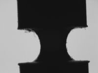
Specimen
If you know what works for you, the next step is quite easy. Set up the measure in Vision Assistant, then select tool-> batch. Select the directory that has all your images in it and tell him what you want to record. Once you have configured, click the run button. I would test it on a small number of images until you get what you want, then run on your set of images.
Bruce
-
strain of understanding using NI9236
Hello
I use a cRIO 9073 with a NI 9236 to measure the strain gauges. I use a modified version of the NI9236 project to start in the folder examples of Labview, make my collection of data. I then use another vi to my shift, average and converting micro strain.
When I apply a voltage to the aluminium bar, on what the gauge is mounted get a negative strain and when I compress I get a positive value. My understanding is that it should be the other way around. Another thing is that, even when I use the value regardless of the sign that i seem to get the results of garbage.
When I add a weight of 311,05 g to a 19mmx3mm bar of Al, I should get a strain of 0.79 stump microphone, no - 19. I see the - 19 on the façade of the .vi OR 9236 Getting Started (host), while it is running, and is not part of the vi that I have edited, rather some thing OR written. I'm sure this isn't a programming mistake, I do not understand the difference. My math may be off may it?
Any help to clarify this point would be appreciated.
OK... maybe a little slow here, it could be useful that I've been in the correct range for the strain gauges... 311g is too little weight to do all the tests with... sigh.
My main question about the sign convention is still topical but, why is it contrary to the way I always thought that the strain must be?
I'll add a few weight of propper on this thing to see what I get values.
Steve C
-
Straing gauges - calibration for measurements
Hello
At first, I'm sorry for my English, I'm Polish and I do what I can

I t prepare strain measure simple application on cylindrical tube. Has created this task to MAX and now I have a problem during calibration. Performed shunt calibration.
The main idea of my program:
After clicking on "run" arrow in the upper-left, I will send to the tab named "calibration"(default tab) (it can also be cluster tab instead, is not serious). "." Then I load sample tested with, for ex. 1000N and the program of calculate the coefficient between the force (1000N) and the real value of NOR-9237 (configured as analog input - bridge to the MAX). Then I move to the next tab, described as '' measure '' when I perform a simple measurement with strain vs.time graph.
I have established that the dependence is linear, so I have to use y = ax + b formula. Assuming that 'b' 0, I have to find 'a' - how can I calculate and how can I keep it for use in the next tab, 'measure '? I have no idea...
I attach no examples of my program, because there is nothing difficult yet - DAQ Assistant and graphic waveform...
DAQmx provides a way to create "Ladders", but also "Tasks" a linear scale is easy to assign to a channel in a task.
I'm in the middle of an upgrade from LabVIEW today so, Kudos to anyone who publishes the screenshots I can't get right now.
-
Configuration NI9219 for measurement of deformation
Hello!
I am putting in place a strain measurement VI using Labview. I use the NI 9219 module on the chassis NOR cDAQ 9172. My extensometer is configured in a quarter-bridge arrangement and I did strain gage connection accordingly (to the terminals 3 & 5 in NI 9219). However, I do not understand what are the terminals of TEDS and what to connect to these terminals. Can I use virtual TEDS for this? I couldn't find a virtual TEDS for NI 9219. Any information to resolve this issue would be much appreciated.
Best,
Nyquist99
Hi, the terminals of TEDS are only for transducers, as a strain gauge, that support the TEDS (Transducer Electronic Data Sheet). The standard of TEDS is just the ability to a transducer to record information about itself in the internal memory. This information includes things like dates and calibration constants, one of the factors, electrical characteristics, etc. It is stored in a standard model which can be read by computers and the DAQ cards via these lines TEDS. For your application, you must just let unwired and to the top of your strain of installation normally gauge.
-
I'm not much of a user of Illustrator (5.0) so it's probably pretty basic.
1. I am changing the scale in percent but can not see the option anywhere. I looked in the help of Adobe and it shows show that as an option, but on my screen scaling is only in the measures.
I've attached a screenshot of what I look at. No % option either in Control Panel or the transformation and I cannot see anywhere to bring it.
2. If I have something on the scale and you want to repeat this on another object, adjust turn it once again, but he also moves to a different position on the canvas!
I'm used to these features, how work in InDesign then maybe I need a paradigm shift.

Thaks
Brian
Oh, Brian, you can select all instances and then object > transform > transform each > insert % values for X and Y.
You can select > object > text objects to select all instances them of the Type.
For type described, you can find a common characteristic, such as Select > same > STROKE weight/race fill color/color/background & contour, or anything that may apply.
Or you can select > object > paths of groups/compound / anything that can apply.
-
I could use some serious help. I have a problem that I couldn't solve after more than 30 hours of attempts.
I have a cRIO 9082 with 2 EtherCAT expansion chassis filled with NI 9236 strain gauge modules. The two chassis are running the FPGA code that allows modules to the braided user-defined variables and use of data. All of my FPGA code seems to work very well and I am able to read and present values of strain to the user.
However, after a random time between 5-25 minutes, I'll receive a 66030 attention, all my data strain gauge will be bland, and the 'State of the device online' for the 9144 chassis will be listed as "device disconnected. Using the way hacky setting scanning motor in configuration mode and return to the active mode allows readings to continue, but this approach is unacceptable for my client. This causes ALL my e/s to reset and lose all my control signals of various devices.
If someone has never experienced this before, please help me. I'm pulling on my hair.
Hi OptiJohn,
What are the sounds as you take a few good troubleshooting steps. You can also try to move all of the analytical engine I/O on the cRIO to the FPGA level, if the current measures do not resolve the problem.
-
Hello
I want to use PXI-5105 on SMU 1071 chassis for strain measurment by conneting the strain gauge by the to 5105 wheatstone bridge circuit using BNC cables. I'm using Labview for the same thing.
(i) I get the variable noise (0,008 to 0.010 V) with no connection to the input channel.
(ii) I'm unable to balance / minimise the noise to zero by subtracting signal from one channel to another (differential input).
Data acquisition parameters:
Input voltage: 5V by DC power supply
All cables used are sheathed in copper cables
Sampling rate: 5ms / s
Number of samples to read: 2000
We worked on the reduction of noise for a long time. Any help will be much appreciated.
Thank you
Vinod
Hi Vinod,
Keep in mind the accuracy of the unit 5105 is specified to +/-2mV.
Also, you can check that your device has been calibrated on the outside and in his external calibration cycle.
When I watched a 5105 digital signal in a similar setup to yours, I saw the same kind of (about) + / 2mV noise. I don't think this is unexpected. Especially if you let the front end of your digitizer not completed, it could recover the additional ambient noise.
Why you choose to use this scanner for a measurement of the strain gauge? There are several other products OR Lane County and specifically designed for measures of constraint. Here are a few resources:
Strain with gauges
http://zone.NI.com/DevZone/CDA/tut/p/ID/3642
SMU-43xx Bridge Module Product Pages
http://sine.NI.com/NIPs/CDs/view/p/lang/en/NID/208288
Dynamic signal acquisition board
http://forums.NI.com/T5/dynamic-signal-acquisition/BD-p/100
-Andrew
-
Components for the Acquisition of data for a Sub miniature sensor
Hello
I'm looking to acquire the data of two simulatneously cells (T4 - 100 L Measurement Specialties ELFS) load Sub miniature. The FS it out 100 lbs to 2.83mv / lb. I already have LabVIEW 8.2 and have acquired data using an analog I / 0 but my signal was weak compared to the noise in the system. I am a high speed data capture because the application that I use has an impact.
My question is: what the amplifier signal conditioner and the DAQ combination would be the best for this aplpication?
Thank you
Scott Kramer
Hi Scott,.
Welcome to the forums EITHER! Looks like you might be interested by the 9237 bridge and strain measurement Module. The 9237 comes in a USB, Ethernet, or Wireless channel, or as a stand-alone module for use with a cDAQ chassis. The 9237 offer a 50ks/s/ch sample rate, up to 10V of internal excitement which should reduce the noise from your system. Based on what you mentioned, it's the product I would recommend - you can find the manuals on the links above to verify that it meets all your needs. There are additional specifications that you need?
-John
-
"Bridge shun cal.vi" shunted the setting of the value?
I copied the "bridge shun cal.vi" LabView example "Acq gauges bridge samples (with calibration) .vi", to include in a strain measuring .vi I'm working.
My equipment consists of an SCXI-1001 chassis, modules of 1520 and 1314.
That means the acronym for setting the value of "Shunted"? Resistance value of triage (in ohms, I supouse)?
And it's less important to me, but think it may be interesting for others: how to choose between the calibration shunt resistance is or B?
Thank you
usuario
Hi user,.
You are right when you say 'shunt resistance' in VI stands "DAQmx perform Shunt calibration (bridge)" for the value of shunt in ohm resistance. As you can see on page 4 of the SCXI-1314 manual, the two shunt calibration resistors A and B are have a value of 100 kohm. In addition, page 4-28 the SCXI-1520 user manual specifies that they are are in style RN-55 (standard 1/4 W).
Choosing to respect so shunt calibration resistance A or B, the latter manual mentions on page 3-4 that "shunt calibration switches A and B are parameters of control of software that allow or activate or deactivate the shunt calibration resistors in order to form win calibration." In most cases, you do not explicitly switches shunt calibration check, he makes instead of software driver to automatically adjust them for you during the shunt calibration procedure automated. However, if you want to explicitly control the witches of calibration, you can write an application program which controls the shunt calibration switches.' and returns the user to Chapter 4, principle of operation, for more information.
I hope this helps.
Kind regards
-
Hello. I try to take a data of torque on the shaft with the strain measurment (half bridge with 2 meters on 45 degree system). Every time when turn on data zero offset starts at 0 and then move to 80 Nm. The problem is that jump. I don't have any load to have that jump and I prestressed State. I use filtering (low-pass 1 Hz) for noise static System. Can someone help me with which jump problem. Thank you.
You use a filter low low pass of Veery... so start acquisition, wait for the filter to move, use DC estinate vi on a long datablock and subtract this value from the following data (after filtering, or wait one more time the filter set...)
You'll run out of memory
-
Measure the voltage of strain gauge
I have connected my 9237 to a 9945. I use a 350 ohm strain gauge. I have the voltage set to 2, 5V Max is there a way to measure physically to be sure that it is 2.5V? Also, in my vi I use a DAQmx create function of the channel. I want to add another channel for this but can't see how to do it.
Thank you
HS
Hi, Harry, it's Paul with engineering Applications to the OR.
My first question is why you are wanting to physically measure the voltage?
If you are wondering how that tension may vary, it is limited by the maximum capacity of 150mW of your device, as explained here: http://digital.ni.com/public.nsf/allkb/7CBC67482CC9FB318625758C0048FF73?OpenDocument
If you want to continue to measure externally, you have a few options. You can use another DAQ hardware to measure the voltage, or you can use another external device, like a digital multimeter.
If you want to see in the excitement that is actually supplied LabVIEW code, you can use the node property DAQmx 'Value of real excitement'.
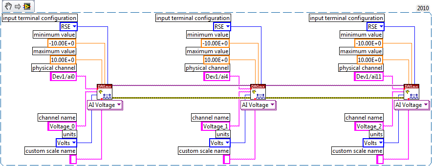
As far as playback of multiple channels, theres two ways you can go about it. If your channels are sequential and all have the same settings, then you can change your name of the physical channel to something like 'Dev1/ai0' to ' Dev1 / ai0:3: to specify the first 4 channels.» Alternatively, if you wanted to select non sequential channels, you can chain create channel set tasks, as long as they are of the same type of task (AI voltage, etc.) and the same device, as shown below.
Let us know if you have any other questions.
Kind regards
Paul
-
Heating problems Strain Gage; Wait for the function measurement of delay
Hello
I am able (using four 350 ohm gauges) of the strain using a NI 9237 module with a cDAQ in connection Full deck Type 3. My test is to measure the strain over long periods of time (~ 10 days). The NI 9237 measure strain at a rate of 2000 Hz (this is the slowest rate). The wheatstone bridge is currently powerd with the NI 9237 of 2.5 V. When I get my data permanently, I see the strain increases with time (which it shouldn't do my test), and I suspect it's because of free heating strain gauges. So, to overcome this problem, I think using "Wait (ms)" and ask the program to obtain data once every 5 min. Five minutes should be more than enough to dissipate any overheating of the gauge.
My question is: if I use the function 'wait (ms)', is my sensor (extensometer) are constantly under tension during the time-out of 5 minutes? I think that the functions "queue" are used inside a loop to allow a VI to sleep during the prescribed period (correct me if I'm wrong). So, it means that the sensor is not powered during this time?
Thank you
SID
I wouldn't use "wait" function for your timing... software you can use the time elapsed or other timing functions
-
As a strain gauge measure weight?
Hello everyone. I am doing a project in Labview and I have to measure the weight of the different animals. I was thinking a strain gauge to measure with the NOR-9237 as DAQ hardware. Can it happen? I downloaded a system image.
Thanks in advance
You're still more general. If you want us ethe USB daq, you should have the driver for the acquisition of data so that you can detect the hardware in the window of measurement and Automation Explorer and then take an example of simple data acquisition and trying to work around. Create a task for the channel you are going to connect to the strain/in² and then configure the channel type and etc, and then you're good to go with the stuffs of base (DAQ assistant) in LabVIEW.
-
Hello
Currently, I'm trying to convert the reading of the strain gauge allows to get readings of the strain of a game of strain gauges of configuration of full-bridge at an angle of 45 degrees on a hollow cyllinder. It is set at 45 degrees, because we are trying to get traction and compression strains resulting from the application of the twist, or a moment of torsion, to the cyllinder hollow. Finally, we want to convert these readings of strain in order to get the couple. Our problem is that full-bridge options to convert the strain gauges appear only apply to configurations 0 or 90 degrees. My question is how can I take my current VI and set it to take readings of the strain of an alignment of 45 degrees. Also suggestions on how to add couple of this VI measures would be appreciated. We have scoured the site, but we are very new to Labview.
Thank you!
This is not a very good example, they show. Full-bridge 1 will also read the constraint of torsion. Full-bridge 1 is for any configuration where you get 2 gauges of tensile and compression 2 meters and you expect roughly equal magnitudes. With a twisting bridge, the only thing you need to do is to make sure that the wiring and pay attention to the numbering of gage. Think just mentally on what measurers are in tension and in compression as you twist the stem or tube.
If you're wrong, you pretty much know immediately because you will see very little change in the output when you go to the torsion of the shaft because the templates of traction and compression will liquidate cancel each other in the bridge rather than expand their effects. To fix it, all you will need to exchange a few threads to effectively rewire the bridge correctly.
Good luck in your project.

Maybe you are looking for
-
the contacts accidentally deleted in the collected addresses - need to restore
accidentally deleted addresses in the address book collected. need to restore
-
Firefox 9.0.1 hangs on startup after upgrading (OS x 10.6.8), even in safe mode.
I closed Firefox because some parts of the site, www.washingtonpost.com is more display (icons), and installed Firefox automatically updating when you restart. Then the 'well, it's embarrassing... "Restore Session screen popped up, but the program su
-
Lenovo companion opens no more
I have Lenovo Yoga. It is quite new. Win 10 included. Now, for some reason or another companion of Lenovo is unbootable. It is said that there's a problem and you need to restart pc. But the reboot will not help. I also treid to re - install app comp
-
Rebuild (OS disk) drives can re - install Windows after installation of Linux?
Hi folks,. Question: Can the disks to rebuild (OS + pilots) Re-install Windows, after a Linux installation? Goal: The goal is to alternate between facilities of OS: Linux - and Windows - and Linux - etc. Thanks again, good people. Of a valued custome
-
Well I'm puzzled! I was ofline for a week, but I have recently installed to realpayer, also have itunes and media center. Well, someone removed my music! Beegees to mr. bungle, the files are gone! not in the trash, Whats up? No one else has access to