Several strain gauges
Hello
I'm trying to run a simple application, where several strain gauges is to read, nothing fency. I use an indicator of the gauge to display the strain reading well. The problem is when I connect multiple calibers, I do not know how to assign the individual indicators to different strain gauges, so all my indicators in gauge end by showing the same value. What I want is the different gauge indicator show the succession of different strain gauges.
Material: Labview 8.5.1, block SC-2345, CSC-SG01 measuring module connector, card data PCI-6251 acquisition.
Thank you
Sine
On the block diagram, go to Express---> Signal handling.
You will see some functions to merge and split signals. It is mobile control. You can enter the bottom and drag them down, so you can create multiple entries (Merger) or outputs (for split) as needed.
Eventually you want to get a way to use the Express VI, but they are good for a beginner to get started quickly.
To learn more about LabVIEW, I recommend watching the LabVIEW tutorials online
LabVIEW Introduction course - 3 hours
LabVIEW Introduction course - 6 hours
Tags: NI Software
Similar Questions
-
Reading of several strain gauges (10 to 20 strain gauges)
I work on my ME senior project and I try to read the pressure on the suspension triangles and the stems of thrust for vehicle FSAE of our school. I want to read and data log 5 readings of strain by corner so 20 strain readings altogether. The system must be compact enough to fit in the car.
From my research, each strain gauge will have 4 analog inputs (2 analog channels, one for the constraint of voltage reading and one for the voltage of reading). It would mean I would need 80 analog inputs to achieve this and I can't find a proper data acquisition.
I'll try to find a good solution cheap and easy to achieve and seeks in things like multiplexers to change string beetween to demand less entered DAQ, but it becomes very compliated.
Can anyone recommend a good cheap and easy solution to accomplish this task?
Reference example of strain canal bridge: (http://zone.ni.com/devzone/cda/epd/p/id/6417)
Thanks in adance for any input!
You must first complete circuits bridges. If you plan to use a unique to each place active extensometer, then you connect the other 3 elements (resistors or dummy gauges) complete form bridges.
If you had a handful of bridge circuits, the U3 would be the least expensive option. With a U3 - LV, you need 1 LJTick-InAmp for each circuit of 2 bridges, which would be about $170 to manage 2 bridges.
For circuits of 20 bridges, however, the cheapest option will be a U6/U6-Pro with the Mux80. For a little more, you can go with the T7/T7-Pro for Ethernet and WiFi in addition to USB connectivity. These solutions will be about $450 - $650 and give you 84 analog inputs (you need 40 analog inputs for your 20 differential signals, most at least 1 analog input to read the voltage).
What is the rate of scanning max you need?
There are some more details that we can get in, so you can send us an email to talk more.
-
To win a set of multiple strain gauges
Hello
We are using several gauges of constraint and "Calibration of Shunt DAQmx Perform (strain) .vi" for calibration of shunt. We want to output, gain adjustment, used by the "Shunt DAQmx Perform (strain) .vi calibration" for each caliber. We've had some success using a property node (see attached pictures 1 and 2); However, when we try to use the same method to achieve adjustment gain, any other strain gauges (picture 3), the readings are always 0 (visible) in image 2.
If someone could give some insight on how to get the gain adjust for several gauges, it would be highly appreciated.
See you soon
Bart Scicchitano
(using his account of supervisors with his permission)
Hi Bart,.
You can be is 0 because there are several channels in the same task, then the property node does not know the following. You can set the active channel by using the Active Channel property node. Place a DAQmx channel property node and select ActiveChan from the drop-down list. Give it a try and see if you can read the multiple factors of gain.
-
Strain gauge: calibrate, relaxation and to write to the file
Hello
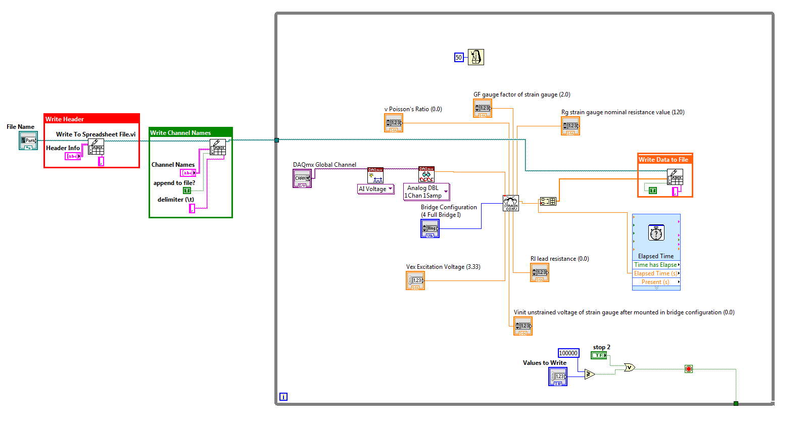
I'm new to labVIEW please bare with me. My title says I'm trying to do. I want to capture data from strain gauge using a trigger and write data to a file. However, I also want to be able to calibrate the strain gauges.
My attached program reads the data correctly with relaxation and stores it in a file, but it does not calibrate properly. If I run the program several times and press the button "calibrate" each time, finally get gauges calibrated after two or three iterations.
Is it possible to change the program so that the gauges are calibrated and then data can be triggered and written to the file?
I'm using LabVIEW 8.6 and NI-DAQmx 8.8.
A screenshot of the front panel is also attached.
So I thought about it, but I'm not completely sure why it works. I didn't remove the loop condition around the calibration block and the program works beautifully. All I have to do is wait about 20 seconds before I hit the trigger for the calibration to be completed, and my gauges will be calibrated when I pull the trigger.
This program works very well for this application. However, it is difficult to change because all parameters are constant in the block diagram.
-
Negative results with strain gauges
When I run my VI the results are always negative. I use the NI9237 with the NI9945. I wired my installation as one quarter bridge. There are three wires from the strain gauge. I went on the wires and I think it's okay / characteristics of NEITHER. Is there something in the MAX that I should be looking. Not sure why the values are negative.
Thank you
Harry Stone
Hi Harry,.
There are a few things I want to clarify:
-Traction deformation is positive and compression deformation is negative, what is described a high level in the tutorial below.
Strain with gauges
http://zone.NI.com/DevZone/CDA/tut/p/ID/3642As strain compression is negative, you would see negative within MAX results if your strain gauge knows any compression. Please keep in mind that a shift can be associated with each transducer, that's why some sensors use a calibration certificate. It is produced by the manufacturer and is provided with the sensor as is the specific sensor. The sensor goes through a testing process to determine its actual response compared to the ideal. In this case, a scale of table can be created to include these values.
How to do a custom able scale & Automation Explorer (MAX)?
http://digital.NI.com/public.nsf/allkb/3F6558112FD2C776862575B5004F7F87?OpenDocumentNot all manufacturers of sensors provide a calibration certificate. Or you can create your own table by placing known quantities of pressure, force, etc. on the sensor and map it to the corresponding voltage, or you can create a linear scale in MAX adjusting the intercept (b) the value necessary to remove any compensation.
You use the NI 9237 that compensated supports deletion. A null offset is executed with the sensor fixed without load placed on the sensor. Actually, a measurement of voltage is taken and this value is subtracted off the coast of each subsequent measure therefore removing the start offset. This takes up space you creating a linear scale and in doing so manually.
The two links below show how to use a custom scale created in MAX in LabVIEW, as well as coding the custom in LabVIEW scale to remove the dependency of MAX.
Acquisition of DAQmx with custom scale
http://decibel.NI.com/content/docs/doc-3706Create a linear scale customized for each channel AI in LabVIEW using DAQmx
http://decibel.NI.com/content/docs/doc-11136I recommend using a task sequence. Input parameters for the information about your strain gauge needed to perform the conversions of strain. There is an example of a measure of deformation in the example Finder LabVIEW (* open LabVIEW * help > find examples) designed specifically for the NI9237 that incorporate deleting the offset and shunt calibration devices. If you do not have external wires connected for calibrating shunt such as cited in this document , you will receive an error. Here is an explanation from the NI-DAQmx help Shunt calibration (start > all programs > National Instruments > NOR-DAQ > NOR-DAQmx help) to help better explain this feature.
Shunt calibration (adjustment of Gain)
You can check the output of a measurement system based on a bridge by comparing the measured output bridge with a calculated value if the physical load on the sensor is known. NOR-DAQmx can then use the difference (if any) between calculated and measured values as a factor of adjustment of gain for each measure. You can simulate the application of a load at the bridge by connecting a significant resistance in parallel with the bridge. This resistance, known as a shunt resistance, compensates for the voltage from zero of the bridge. Because the value of the shunt resistance is known, you can calculate the physical load corresponding to the voltage drop of the resistance.Use the Shunt calibration perform the Assistant DAQ or DAQmx VI/function to perform a calibration shunt, which defines the the gain setting for a virtual channel. NOR-DAQmx then uses this adjustment of gain when you descale readings from the bridge. Some National Instruments products are internal resistance.
This may seem like information overload, but I wanted to provide you with a detailed explanation of your understanding, in addition to immediate responses. As a logbook, I recommend that you use the 9237 strain example and use the removal compensation. Negative values are expected for compression and positive for blood. The handy Guide below gives an excellent overview of the strain gauges, which also includes a video.
Measurements with strain strain gauges: practical Guide
http://zone.NI.com/DevZone/CDA/tut/p/ID/7130Hope this helps!
-
With the help of the strain gauge convert read vi
I'm having trouble with the wiring of the strain gauge convert reading vi. Are there examples of this vi showing how to connect?
Thank you
HS
Have you checked the help file to this topic?
http://zone.NI.com/reference/en-XX/help/371361G-01/lvinstio/conv_strain_read/
There seems to be some examples of stock to use, but the help files for these screws can be VERY useful.
-
Measure the voltage of strain gauge
I have connected my 9237 to a 9945. I use a 350 ohm strain gauge. I have the voltage set to 2, 5V Max is there a way to measure physically to be sure that it is 2.5V? Also, in my vi I use a DAQmx create function of the channel. I want to add another channel for this but can't see how to do it.
Thank you
HS
Hi, Harry, it's Paul with engineering Applications to the OR.
My first question is why you are wanting to physically measure the voltage?
If you are wondering how that tension may vary, it is limited by the maximum capacity of 150mW of your device, as explained here: http://digital.ni.com/public.nsf/allkb/7CBC67482CC9FB318625758C0048FF73?OpenDocument
If you want to continue to measure externally, you have a few options. You can use another DAQ hardware to measure the voltage, or you can use another external device, like a digital multimeter.
If you want to see in the excitement that is actually supplied LabVIEW code, you can use the node property DAQmx 'Value of real excitement'.
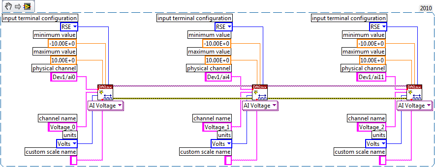
As far as playback of multiple channels, theres two ways you can go about it. If your channels are sequential and all have the same settings, then you can change your name of the physical channel to something like 'Dev1/ai0' to ' Dev1 / ai0:3: to specify the first 4 channels.» Alternatively, if you wanted to select non sequential channels, you can chain create channel set tasks, as long as they are of the same type of task (AI voltage, etc.) and the same device, as shown below.
Let us know if you have any other questions.
Kind regards
Paul
-
Calibration with NI9237 and NI9944 strain gauge.
Gentlemen.
I have a cDAQ9172 OR with NI9237 and the bridge 1/4 NI 9944. Practically, I'm working on measures of strain gauge issues using a strain than 120 ohms connected to the NI9944 to build the bridge half happening inside of 9237. I have a continuous doubt how is the calibration for the strain gauges. The manual speaks of a shunt resistance which, in the case of NI9944, is already in the system. The manual says that I don't have the shunt resistance external nee. It is clear.
My question is this:
the menu for calibration requires a resistance value that I don't know, I'm leaving in the value proposed by the menu of NOR. The strain gauges takes easily compensate, so I always have to recalibrate the channels in the NI9237. Is this normal? Can a (application to 2.0 V strain gage) voltage of 2.5 [V] generates a continuous drift of the measure?
Strain gauges are: EA-06-125BT-120
Hi cgenco,
Because the NOR-9237 with 9944 uses an internal resistance for shunt calibration, you need not to worry about the value of the shunt resistance. Take a look at the following article that specifies how connections are made. Calibration article will show you the basics behind how to exploit.
Also, since there is a ratiometric measurement, the voltage is 2.5V shouldn't matter as long as your pawn takes care of everything.
-
As a strain gauge measure weight?
Hello everyone. I am doing a project in Labview and I have to measure the weight of the different animals. I was thinking a strain gauge to measure with the NOR-9237 as DAQ hardware. Can it happen? I downloaded a system image.
Thanks in advance
You're still more general. If you want us ethe USB daq, you should have the driver for the acquisition of data so that you can detect the hardware in the window of measurement and Automation Explorer and then take an example of simple data acquisition and trying to work around. Create a task for the channel you are going to connect to the strain/in² and then configure the channel type and etc, and then you're good to go with the stuffs of base (DAQ assistant) in LabVIEW.
-
Compensation of temperature for the strain gauges
I'm trying to compensate for the effects of temperature on an extensometer placed on a sample of carbon fiber. The sample will be only responsible uniaxialement. The temperature is a major concern here, for an electrical current will be executed by him for purposes of measurement, which should also heat the sample. I read in the document 'Strain gauges measure' on the website of NOR (http://www.ni.com/white-paper/3642/en), but he speaks with a Measurer of mannequin, he speaks not just how this second pledge, placed perpendicularly to the axis of the applied force, we are not talking of how connect to the strain gauge module , in my case the NI 9235, to use for temperature compensation. My first thought was just connect each pledge to the module as their own separate channels, using quarter-bridge in the LabVIEW software set up, calibrate the two gauges while not external physical load or temperature effects are applied, and then, after the test, by subtracting the measure pledge Sham in the values of assets pledged. But then I started wondering, is there a better way to do this? Can I use the half-bridge configuration, or some other configuration with the 9235 to automatically merge the readings two pledge during the test?
I'd appreciate it really any advice that anyone can give me on this. I don't want to build my own external wheatstone bridge (other than the built-in NI 9235), and I would like to make these measurements as accurate as possible. I have also considered the possibility of the compensators measurers, but I don't think this would be applicable in this case, the complexity of the matter - being a composite.
Hello WyoEng,
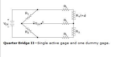
You want to use the temperature compensation is referred to as a quarter bridge II configuration (image below). This configuration is very similar to a half of the bridge, while the second element (R3) is inactive because it is placed transversely to the direction of the load, without strain and in the same location the active gage (R4) to take account of thermal affect.
NI 9235 supports only a quarter bridge I configuration for measures of constraints. You will get an error if you try to use this module for any other configuration of pledge of strain that is not quarter bridge I. Thus, active policy that you asked to use two channels to read the pledge and the dummy gage will be the best option to use NI 9235 to compensate for thermal effects on your extensometer.
Another option would be to look on the NI 9237 which supports a quarter bridge II configuration.
Best regards
Izzy O.
Technical sales engineer
National Instruments
NI.com/support
-
Hello
Currently, I'm trying to convert the reading of the strain gauge allows to get readings of the strain of a game of strain gauges of configuration of full-bridge at an angle of 45 degrees on a hollow cyllinder. It is set at 45 degrees, because we are trying to get traction and compression strains resulting from the application of the twist, or a moment of torsion, to the cyllinder hollow. Finally, we want to convert these readings of strain in order to get the couple. Our problem is that full-bridge options to convert the strain gauges appear only apply to configurations 0 or 90 degrees. My question is how can I take my current VI and set it to take readings of the strain of an alignment of 45 degrees. Also suggestions on how to add couple of this VI measures would be appreciated. We have scoured the site, but we are very new to Labview.
Thank you!
This is not a very good example, they show. Full-bridge 1 will also read the constraint of torsion. Full-bridge 1 is for any configuration where you get 2 gauges of tensile and compression 2 meters and you expect roughly equal magnitudes. With a twisting bridge, the only thing you need to do is to make sure that the wiring and pay attention to the numbering of gage. Think just mentally on what measurers are in tension and in compression as you twist the stem or tube.
If you're wrong, you pretty much know immediately because you will see very little change in the output when you go to the torsion of the shaft because the templates of traction and compression will liquidate cancel each other in the bridge rather than expand their effects. To fix it, all you will need to exchange a few threads to effectively rewire the bridge correctly.
Good luck in your project.
-
Organize the maximum values of magnitude of several strain gages according to their location.
"There are 32 gauges installed on a 53' (is) 636" span beam which are 20 ' apart. The first pledge is 26 "support. The attached vi gives the amplitudes of the peaks of each pledge individually by changing the columns and rows in the control. Now, these maximum values should be prepared according to the spacing of the beam and join these points with a spline curve.
Open the vi, give the path of the attached excel sheet. Now, in the beginning cluster attribute column 3, 620 to line in the end cluster assign to column 4, 845 to line. Now, run the vi. Assign the columns start and end must be (3,4), (5,6), (7,8) and so forth, to get the maximum amplitudes of each extensometer.
Vlaminck
Greetings Vgrchada.
You can independently change the column and the row of every beginning and end by a beam control based on the name. Look at the example that attached. I changed the star and end constants controls because they will be handled programmatically (so there is no need for human beings humans interact with them) always use for the line start and end values, because there is where all the data are. As for the columns, use the iteration of the loop counter For (with differences appropriate, while it starts where it should) another possibility is to build a table with all indexes and use the property auto-index of the loop For (this in the case where the columns are not side by side).
I would like to know how it works. (I have not tested this code, but the principle should at least help you find your way)
Kind regards.
-
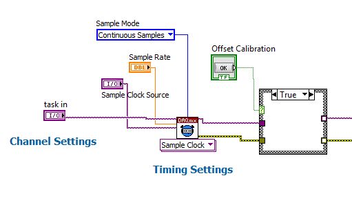
Place a button for calibration of the strain gages on the façade
Hello
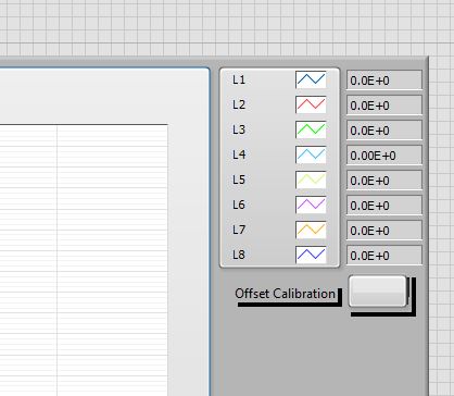
I'm relatively new to LabVIEW, and I'm trying to place a button on the front of a VI that is designed to graphically view statements for voltage of several strain gauges. I tried to use the offset calibration DaqMX bridge Subvi initially, but is not the same thing as the calibration button of the strain on the device tab in MAX.
Can someone help me to do it properly? I know that's not much more difficult to just do the calibration in MAX, but my supervisor is looking for the VI to be as simple as possible for the user.
Thank you!

for a project that I use on average for gauge calibration chain
I Place a button when the press op that he finds the average of the last ten value of voltage and then I use it as V0 in the vi strain using shift register
is this great method for you?
If so I can give you examples of code -
Scaling of NI 9236 strain measurement
I'll put up several strain gauges in a quarter bridge configuration. I'm confused about the output of the measurement range. I set up the channels with all the features of the gauge (GF = 2, resist = 350 etc..) The measure returns values ~ 5 x 10 ^-3. I don't know the units of this measure. It's 10 ^-3 microstrains or 10 ^-3 strain. I wouldn't believe 10 ^-3 strain. 10 ^-3 microstrains are too low. I expect microstrains 1-5 in this measure. Because I enter all the scaling in the measurement task, I expect an output correctly to scale, but it is difficult to interpret. Change the GF is going to change the output in response, once again this points to the fact that the output is indeed scaling my input parameters and should represent the strain.
Any help would be greatly appreciated.
Hi ludhaber,
If you use a task sequence, the values returned must just be in units of strain. So, you should see values with either a me ' (representing milli-) or a 'u' (representing Mike) - next to the value such as "2 m". A good method of checking scale is to use the task type "Custom with excitement of tension." This type is very similar to a task sequence, except that it does not return a value in terms of voltage (it is indeed volts by the voltage, change the excitement value of a template will change its output voltage, even if the amount of strain cannot be changed). The value returned here must match the equation for a strain gauge quarter-bridge for a value given in the series, shown below. For example, a strain of 5u value, you should see a flow of 0.0025mV / V being returned using the voltage custom with reading excitement. If you read a strain of 5 m in the task of the strain, you should read a value of about 2.4876mV / V to the tension with the task of excitement. Hope this helps,

-
How to connect the chassis cDAQ for strain gage
Hi, when I read the guide of the extensometer of wiring on a chassis cDAQ (http://www.ni.com/white-paper/7130/en) I found confusing fig 10 .
What are the things between the chassis and the extensometer?
The three wires go only one channel of the cDAQ chassis? (in Fig 10, on channel 0?)
Why there are four terminals (CH + EX + QTR EX-) on the strain gauge, but there are only two wires coming out of my extensometer? What should I do?
PS. I have a USB-4431 cDAQ and a Vishay extensometer (http://www.vishaypg.com/docs/11297/250lw.pdf)
Thank you very much!
Elly
ZSH2010,
The 9219 will work. You will need to use a measure of Bridge 2 son resistance measure quarter vs. For more information about how to use the 9219 for 2wire resistance measurements, take a look at the 11 and 15 of the document specifications page
http://www.NI.com/PDF/manuals/372407a.PDF
It will be slightly less accurate than the quarter for the 9237 bridge accessory, but still needs to do the job.
Kind regards
Maybe you are looking for
-
can you replace a hard drive on a macbook pro
a hard drive on a macbook pro can be replaced.
-
ProBook 430 G2, touchpad pointer freezes randomly
Product: Probook 430 G2 System: WIN7 pro. 64 bitDear HPI bought a probook 2 weeks ago and the touchpad randomly freeze when I use my laptopI tried the synaptics driver version 17.0.18.8, 18.1.8.1 and 18.1.15, all versions have the same problemSometim
-
Hello I have iphone "6s more ' 64 GB (IMEI: *) I have forgoted Apple ID and password! now, after reset setting and restart the iphone, and need to apple ID and password. What should I do? the my iPhone is unuseabled < personal information under the d
-
A satellite - cannot use the webcam - in use by another program?
Sometimes a reboot works but not very often. The camera assistance software says "in use by another program.How can I find the other program so I can stop it?I already rebooted the software nothing works. Reg
-
Startup Repair cannot fix issues and vista will not boot
I have an asus laptop. A few days ago when I tried to run vista, he began to display a Startup Repair window: If problems are found, Startup Repair will fix it. Then it takes awhile, and then he said that he could not fix the problem, and the details