Simulate the loop Signal splitters
I am using a loop for the phase shift signal simulated on a 360 deg. My loop will change, amplitude, frequency, offset, but it will not change the phase, is - anyone know how I can do this? I have attached a code that indicates the fundamental problem.
Great! I should really like to try the reset signal entry. Thank you!
Tags: NI Software
Similar Questions
-
Weird behavior with Signal to simulate and loops
I'm having a weird behavior with Signal to simulate and while loops. Attached a photo of my program. The problem I have is that when I use Stop to stop inside while loop, then use to restart the inner loop, simulate Signal instantly generates a bunch of points of data between when I pressed Stop and Go. By example, if I stop for 5 seconds, wait 5 seconds, then press Go, it will instantly generate data for t = 5 t = 10. What I need is for the generation of signals to stop when I press stop and continue where it left off when I press Go. How can I accomplish this? I have no idea why he exhibits the behavior described in the first place.
Hi optometry.
Can you give us a screenshot of the configuration window for the VI express to simulate signal? I was able to reproduce the problem when I used "Simulate the time of acquisition" at times, but the VI's are featured as you described you wanted when I used "run as fast as possible." Have you tried this setting?
-
Simulate the sine wave using LabVIEW FPGA with NOR-myRIO and display in real time
Hello
I'm relatively new to LabVIEW FPGA. I am trying to test (and later apply) controllers high speed on myRIO.
At this point, I'm trying to simulate the sine wave from 1 to 10 kHz using Sinewave generator VI express. I also intend to display the sine wave on the time real (RT) using FIFO. However, I had a bit of trouble to understaing various synchronization parameters.
1. how to encode information about the sampling frequency generating sine wave? (The side FPGA vi requires only the frequency of the signal and possibly phase and does not rate update lines)
2. how to estimate the number of items in a FIFO? (that is, the relationship between the rate of updates to loop (RT), the signal frequency, sampling frequency and the number of items in the FIFO)
It would be great if we could share a very simple program (side host and target) that did something similar.
Thank you
MILIN
Milot,
I think the problem is the type of data in your FIFO. Your FIFO is configured to use a data type of I16. The problem is the number, it displays only ever will be-1, 0 or 1. To resolve this problem, you must send the sine wave as a fixed point data and convert it to a double on the side of the RT. This should significantly improve your resolution.
-
FPGA: the internal signals in ModelSim display
I have a piece of code written LabVIEW FPGA in that I am trying to simulate in ModelSim. I followed the instructions in this link, but the example is a simple incrementer with no internal signal (only the input and output).
I created a test bench and started the simulation, but the macro provided .do only adds the entries and exits to the wave window. ModelSIM lists pages and pages of processes and signals that can be added to the waveform window; all have names completely opaque. I found something called 'TheWindow', and then a subdirectory called "Thatcher" and added all these signals to the waveform window. The names are things like ResHolder00000000000001 and provide no information on where they came from.
I tried to assign labels to the sons of my LabVIEW diagram, but that did not help at all in creating useful names. I need to check the progress of States in my VI but can't find anything that seems like the appropriate signal. A lot of available under 'Thatcher' waveforms are waveforms static, uninitialized, or both. How can I assign names to internal signals so that the waveforms are actually intelligible?
On a side note, it is also a problem in the synthesizer. I'm used to using the synthesizer output to 'pre-debug"my code, but LabVIEW seems to ignore the process of inference any macro. I tried to put a SCTL with an incrementer and LabVIEW does not infer a counter. I have never seen one of my machines of State recognized in the synthesizer, even if the code works correctly.
Using ModelSim PE 10.3, I understand is not "officially supported", but the fact that the synthesizer and the Simulator have the same denomination made problem wants me eliminate this as a problem. I do not use one of the PE extensions on the version SE.
Hi Nick,
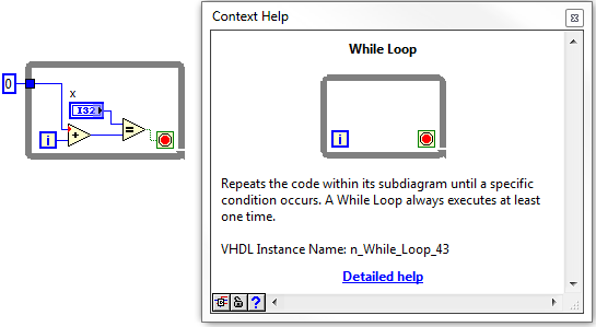
If it is not the most readable, its not too hard to find signals that you are looking for. Your biggest help will be context-sensitive help in LabVIEW. If you hover over the structures, nodes, or son, in your LabVIEW FPGA design, at the bottom of the help context window, you'll see what we call the 'name of the VHDL Instance".
Once you navigate through the hierarchy down through the window, in the VI, you should start to see some of your top-level objects, such as while loops etc. From there, you can navigate down in whatever the level and find the wire you are looking for.
I did not have the ModelSIM on my machine, but it works for the ISIM. I wish they had a search function, so you can just type in the signal you are looking for.
-
Hello
To check my software, I want to simulate some signals on the entrance of the simulated NIDAQmx Council. Is this possible?
I created the jury simulated in NI MAX, but I know not how to simulate the signal on the inputs and run my software (in C language) in order to acquire the data.
Thank you
Theinput signal of the simulated device is built-in, you can't change it. It is better to write your own piece of code that simulate the signal.
-
Cross spectral power and consistency of the 2 signals
Hello
I try to get the cross-spectral power and consistency of the two signals. I should be able to get this:
"The cross-spectral power and consistency of these 2 signals have been calculated on a window (8.5 minutes) 1024-sample using the fast Fourier transform applied to the 3 overlapping of the panes of 512-sample in the window of 1024 consistency." In each pane, the data were the first linear straightened and with windows by using the Hanning (cosine) function before the calculation of the Fourier transform. The 1024 coherence window was so advanced by 256 samples (2.1 minutes), and the calculation repeated until all BDUS/interval of N - N series have been analyzed.
We used the product of consistency and the cross-spectral energy to weight these 2 effects in order to quantify the degree of the hitch.
I should get this chart type
The RR signal I straightened before that trying to get the power crossed with sampling freq = 2. And I put 2 ways to get it.
consistency too and later the product of the two. Im trying to get the spectrogram and watch later 3d like picture.
I have attached the vi.
Consistency is perhaps badly fixed.
Thanks for the help, guys.
Kind regards.
you made a few mistakes, example en by overhauling it you can't do the segments overlap, that's why you should go with a loop and the creation of a subset (and this is why I suggested para window ASD)
You must also set the indexing of the product release and do not concatenate, penny you released 2d end that you can use for 3d graphics
FS in the mathscipt should also be in hz, not in seconds, I told you the last time (he is shown in the help)
-
Problem updating my state machine, using the emg signal
Hello
I have problems with my code. My entry is an EMG signal that I gather from three different electrodes using usb 6008. In the program, I divide the signals and display them in a chart that is unique. What I want now is to read the signal, and if a signal passes a threshold I want an LED lights. This must remain lit until there is another signal that passes the threshold.
To put it simply: "large enough signal--> lamp on--> stay informed--> enough large signal--> lamp--> stay off the coast and then start again."
I tried a few different approaches, but I decided using a state machine. Now, the problem is that when the signal to enter the state machine the program crashes. I think it's because the table that I use to convert the signals does not update when I get my state machine, so the signal stops to come. But how to get around this problem? It is even possible to code what I want?
I have attached the code. All the tips are welcome, I have been struggling with this for some time now.
Thank you
jenmich
The problem is internal while the loop is run until the stop condition is true, but he never does a new Boolean entry. So that it remains for always in the same State. Remove the inner loop and put the shift register on the outer loop instead.
You must also use a daqmx configures the element, and then set the properties of daq. The read.vi can be set to read a number of samples of each iteration.
Also: you can expand the table to index for several items of output. If you want that element number 0, 1, and 2, you have yet to wire the index entries

-
Hello everyone.
I have this problem: I do a simulation of the propagation of the signal between a Tx and a Rx, but I need to simulate the delay between the two points. The signal I want to delay is QPSK modulated with the modulation toolkit. The point is to show the original signal from T0 = 0 s, including the delay (same signal but with T0 = delay time in seconds any value).
Thank you
David
That tal Falastiny,
Sin problema pudieras explicarme the situation in Español adelante, como primer idea if you any that generated UN arreglo N elementos con valor 0, mediante the Relación of how many elements present UN segundo, there an este arreglo al final signal that estas simulando agregues para despues visualizarla en the grafica. Te recommend revisar functions to build array y dandole language the CONCATENATE entered opcioon selecciones.
Te Le los foros también los puedes crear en Español, are una gran comunidad you can support. If tienes dudas por favor comenta, saludos.
-
Trying to simulate the device USB-6366 (without success)
I read through the tutorials DAQmx and MAX about the simulation of the device, but I can't yet find a way to effectively simulate the acquisition and generation of a signal using a device USB-OR-6366.
I am a (given at the entrance of this VI) signal using DAQmx Write and then use DAQmx Read to read the signal captured from the internal memory of the card (which has a buffer of 32 MS). To do this, I created a task with DAQmx I feed in the writing block.
I know that the approach is most likely wrong, but I can't understand not just how to do this in a simple way and documentation of NOR is anything but simple. All I want is to
(a) test using 2 digital inputs to capture this signal by the device and then read what she has gained from its internal buffer
(b) send the same signal to 2 digital outputs the signal output again.
See you soon
Yes! the simulation is designed to allow you to write a program and check that it works theoretically even if you do not have the material physically available. It has no interface programming to influence on the what the reading functions will return simulated data. And write the function has no notable effect anywhere, working as a receiver of data in nirvana. It is always useful because you can test software without getting all kinds of errors on the non existing hardware access attempt, but it has its limits, of course. However, a programming interface for manipulating that which and how the data are simulated, while it would be a very interesting feature, is almost certainly to complicated not only to implement but also to use.
-
[FPGA] Problem with the sinusoidal signal generator
Hello!
At first I want to apologize for my English is not my mother tongue.
Hardware and software I use is:
LabVIEW 8.5
NEITHER RIO 2.4.1
NEITHER cRIO-9014 (controller in time real CompactRIO)
NEITHER cRIO-9104 (chassis and FPGA)
NEITHER 9264 (16 channels, +-10V, 16-bit voltage analogue output Module)
I made a very simple FPGA VI: a while loop, generator of sinusoidal signal and a FPGA of e/s node in the loop. I've specified the Gnerator settings by following the path:
Frequency = 50 Hz
Amplitude = 1
Phase shift = 0.00
Size of the table look-up = 1024
= 16-bit amplitude resolutionFPGA clock frequency (40 MHz)
But the wave of "sine" I got is not what I wanted to get. First of all, its amplitude is 1 V. shouldn't it be coded on 16 bits? If I wanted to get 1V I should have specified Amplitude as a 3277. In addition, 'sine' is not very detailed, it's look like "steps", as many samples vere missing. What I did wrong? I checked the samples and tutorials, I did everything the same way. A I forgot something or not has not specify other parameters?
Thanks a lot for your help!
OK, I solved a problem. It's embarrassing to admit, but maybe this will help someone else
 I blame my inexperience
The main solution to the problem was changing calibration of calibrated RAW Mode. After that, everythoing works as expected. I had a problem with a sample because I was using a multiplier to control the generated sine wave amplitude. But... She was set to 1 in the sinusoidal signal generator. That was the reason for waveform Gradin. Please, don't laugh too much

In any case, thank you for an answer! It is now resolved
-
Simulate the structure of the event in the LabVIEW base?
I have a basic version of LabVIEW (v8.6) who doesn't have the structure of the event. I found it was quite embarrassing monitor the status of several controls (action after clicking a control depends on the State of the other control (s)). Especially if I want to add another function (control), the effort exponentially increase with the current number controls
I had an idea to simulate the structure of the event using "shift register. First, I will provide all the values for the controls in a cluster. Then I'll put the cluster in a while loop and compare the value of the cluster to its previous value (xor the registry change). If the result of the comparison is false (none of the control is changed), the program moves to the next iteration. If the XOR result is true (one of the control has changed), then the program goes into code (it will pass what control has changed and the entire cluster) event management. So for each change of control, we can write an independent code to process the event. After processing of the event, the event was allowed.
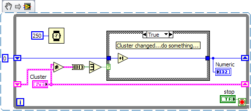
Here are some of my ugly code currently used to monitor multiple controls. And I think rewriting using above idea so there is less chance a hiden bug.
Comments, suggestions?
I'm not quite sure what I'm looking for on your photo of your block diagram because it seems that only the lower quarter right in your code. I would do the following to detect a change in a cluster without the structure of the event control:
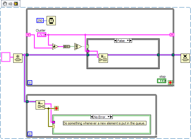
The basic package include the notifications than us? You can put your "event management" in another thread by this method:
The advantage here is your main loop of the program is not "bogged down" every time that a change in your cluster held. It also allows to separate the code so that it is cleaner.
Hope that helps!
-Fisher
-
PtbyPt filter FIR in the Loop Simulation
Hello
Currently, I am trying to simulate the power in my engine when I apply a voltage step for 20 MS for that I intend to use a FIR filter in the control and simulation module that simulates the other parts of the engine.
However, I have found that the FIR filter seems to be strange behavior. When I change the order of Runge-Kutta 1 simulation to 2 of Runge-Kutta it effects the output of the filter FIR PtbyPt VI. The two attached images show how the results of the convolution of the IR and the tension, the FIR outside the simulation loop filter and FIR filter in a loop using Runge-Kutta 1 are the same. However, the second image shows that the FIR filter in the loop simulation Runge-Kutta 2, has a different answer.
Why does this happen? As I understand it, the type of simulation should have little effect on the application of a FIR filter based on pt by pt. I have not changed the timestep or other parts of the simulation. I want to use a simulation of order higher than for other parts of Runge-Kutta 1 would be insufficient for the simulation.
I'm using LabVIEW 2011 SP1.
Thank you
Rhys
When you try to use RK-2 or higher order, the screw that dumped you inside the control and the Simulation loop, by default, they will all run in the "minor" time steps too. In your case, 'two times' which means the VI will be executed each time step.
To properly configure these screws, you must "right click" on the VI and select "Installation of the Sub - VI node. This will bring to a Setup page that the second half you will choose in 'Type of Simulation Subvi execution' to 'remove' the "Include minor steps" box and press OK. When you do this, the Sub - VI will be annotated on the upper right with blue 'C' and when you run, it should provide a similar result as RK-1.
Note that in this dialog box, you can also select discreet, which, in many cases, it is the right selection for 'discrete' systems
I hope this helps...
-
How can I control the working time so that the loop structure in the cases where the structure?
Hi all
My job is: Loop While structure generates the signal for 4 seconds when you press the 'start build' button, after that data has been backed up. You press the button "generate the beginning' once again, and the loop runs one again.
My problem is: the first pressing, the loop, exactly 4 s (3, 999 s), but him second, third pressing on... The time elapsed is not 4 seconds, always smaller (even ~ s 0.003). The loop works correctly after press the "Exit" button and launch the program again.
How can I control exactly time loop work While Structure without the press "Exit".
Thank you any help!
P/S: I used the number of cycles (ms) just to look at a working time of the While loop.
NMCuong
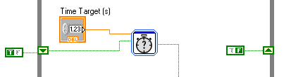
This shows a quick solution
-
Model in the loop timed While the elapsed time
Hello NOR community,
I'm trying to use a while loop timed to run controller simulated for a mechanical system test. I need the time loop to run at an even 50 Hz to simulate the controller that will eventually drive the mechanical system. To check the speed at which the loop runs, I made a VI that gets a value from each loop clock and subtracts the value of the clock of the current iteration of the value of the clock of the previous iteration. I have eliminated all other codes this VI except for the recovery of the clock, to ensure that no problem with another code in VI. I find that the time between iterations is not constant, but it is consistent. In other words, the elapsed time can change at each loop, but it changes according to a specific model, such that the average elapsed time is equal to the value that I use for the timed loop. The loop will run faster than posed for several cycles, then slow down during a cycle even at the same time. Here are some examples:
Running at 5 Hz: elapsed switches schedules between 0.203125 and 0,187500 seconds
Clocked at 8 Hz: time is constantly 0.125 seconds.
Operating at 10 Hz: elapsed switches schedules between 0,109375 and 0,093750 seconds
By examining the differences between elapsed time and the stability of the 8 Hz setting, it seems that there is a minimum time of 0,015625 seconds (64 Hz) division. It is much worse than the 1ms accuracy claimed in documentation. This could be the cause?
I am running Windows XP with LabVIEW version 8.5.1 and have observed this behavior on several computers with different screws
Thank you!
Erik
Your problem is the function that you use to get the current time. It's just the time of the Windows clock which has a resolution of 16 msec.
You must use the function of number of cycles as Jarle has pointed out.
-
simulate the arduino serial monitor
object: simulate the monitor series of Arduino on lab view
problem: I'm working on a project of graduation of scale and arduino interfacing
I use an amplifier for the load cell signal, so I have to load the code from the amp to the arduino
everything is good with the monitor of the series and I get the readings that I'm looking.
I can simulate these reading lab for further analysis view?
Thank youhttp://forums.NI.com/T5/LabVIEW/Darren-s-weekly-nugget-06-28-2010/m-p/1162899/highlight/true#M508346

Maybe you are looking for
-
How can I keep an old e-mail account in Thunderbird, but prevents all synchronize?
I want to keep his files and emails from Thunderbird, but the account is no longer in use. How do I keep synchronization?
-
I'm trying to find a plug-in for FCPX that will allow me to compose a title and then do break into small pieces. Suggestions please - especially if you know a free plug in this type Thank you Chris
-
I have recently updated for firefox 3.6, I think that the inability to access firefox began after that. I'm worried if I have lost my favorites. This has happened Each time Firefox opened Since last week, when I try to click on firefox User Agent Moz
-
Need info on soware delivered with Satellite A200-1FJ
Hi all Windows Vista is preinstalled?Offer a copy with the laptop? What is driver disk? I just got a recovery with my laptop disk.Someone bought the laptop for me of the Kuwait. Can someone guide me on the dvd provided with the laptop. Best regards M
-
Hi guys,. I want to create a parallel thread with an inside .VI. How can I create one and how to set the priority and the time interval. This .VI checks whether a device is present alwayz. I want that this thread started after a while.