Simulation loop ODE Solver
I get error 2324: Labview Simulation Module: the ODE Solver cannot meet the tolerance of errors using the minimum landing size. I've broken down my code and my function of propagation of the signal seems to be the cause. If I multiply things, it works fine. If I do, I get the error. Any ideas?
Thank you
Brian
Tags: NI Software
Similar Questions
-
Function of memory in the loop control and Simulation - problem of the ODE Solver
Hello
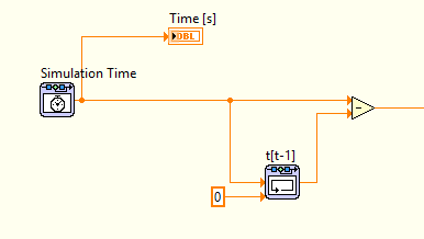
I'm correctly using the control loop & simulation to simulate the behavior of what is essentially a shock absorber-spring-mass system. In the process of change in time (dt) is used to integrate an arbitrary value. I use a rack depending on memory to store the time, to calculate the change of time (dt).
The simulation is quite complex, because of the precision required, not all the ODE solvers can all support. Currently I use the Adams-Moulton method, this works very well for the simulation. However, it cannot detect the change in time, the change is constantly zero. This problem has auto market by using an another ODE Solver, but then the simulation has been messed up instead (even when I listen to the step sizes and tolerances). So I'm pretty confident that Adams-Moulton is one of solver ODE best suited to the problem at hand.
Is there another way to store the previous hour and use it calculate lag, that the use of the memory function? Everyone knows about these problems before?
I did a lot of research of error using the probe, but I'm sure that there is a problem with the ODE Solver and memory function. See the image below, showing basic how is calculated the change in time.
I'm pretty new to LabVIEW, so if there is something else I missed I would be happy to hear it.
PS! I set the tolerance minimum step of size/relative and absolute for the Adams-Moulton to simulate the behavior of the system properly.
Problem solved!
It turns out that the ODE Solver has struggled because of two "table 2D find" used functions. This was created for the interpolation/extrapolation, which caused a problem constantly and the ODE Solver could not resolve correctly, so the functions of memory doesn't work does not correctly or the other.
By increasing the table manually, I could use closest method instead, with also good results as interpolation.
-
Hello world
I'm trying to simulate all of the ODE in LabVIEW using ODE solver VI. I do not receive the correct results for some unknown reason.
I enclose my VI with equations saved as default value. However, the curve should look like that fixed.
The ODE are correct and the same set of equations are tested on other tools that produces correct results (see the graphic image attached).
Please let me know what could be the possible problems.
Thank you.
Concerning
HB
-
Variables in the function MathScript ode solver
Hello
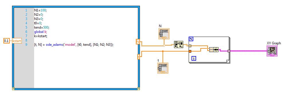
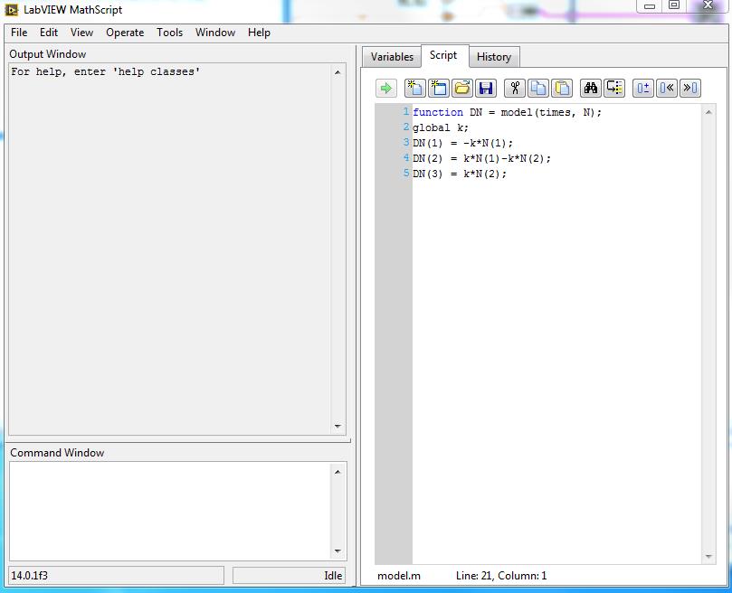
I'm using LabView for awhile and I started using the text tools more. To solve a system of differential equations, there is this very elegant tool to do this in a MathScript node with the ode solve algorithms (for example, "ode_adams"). As the LabView help said, I've defined a function and registered as a ".m" file. I loaded this function in mathscript and solve differential equations.
Both and so good, but my problem is that I can not all variables in the function. I can only put numbers in the function but not variables. Unfortunately I need to define the variables outside the function in the MathScript node.
Does anyone have an idea how to manage the variables in this case?
I have attatched a picture of the function and test VI (LV2014).
Greetings
Global variables to solve this problem:
Solution:
Greetings
-
Cannot compile control & Simulation loop
Hi, I am trying to compile a simulation, and the problem is a feedback loop
which is not accepted.
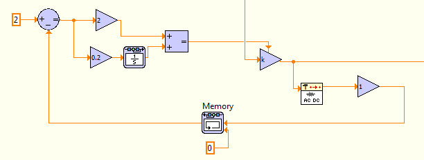
I want to write a program that removes the signal of its DC component and controls the amplitude of the remaining AC signal
Thanks to a feedbackloop. The PI-regulator controls the gain of an amplifier.
Hello laskar01,
Instead of the feedback, use VI memory node. Your problem should be solved.
-
Satellite C660 - 115 Win7 update stuck in the loop. SOLVED!
I have a Satellite C660-115 which is stuck in a loop "of despair".
I am a COMPUTER engineer support and a customer brought this laptop of mine, who was stuck in a loop of repair Win7 (64-bit prem) that simply says Win7 could not be repaired.I backed up the profiles of subscribers using Hiren boot CD (done chkdsk as well - everything is OK), and then did a factory restore.
No problem at all with the restoration.Started doing the updates for Win7; SP1 seems to install OK without errors.
The system then picked up 37 Win7 updates automatically and asked to reset.
Upon reboot, Win7 entered "drvload.exe" and started an auto repair.
It took time and the system started OK, but without any sign of SP1, looks so much like system restore to an earlier point?I though this update to process 3 times now and each time after that a lot of auto update, the same sequence occurs.
How to exit this loop? What is causing this problem, which I have never seen before?
No software has been installed, other than that of the recovery process.
I even uninstalled McAfee, just in case this could be a problem - no change.Ah, just took another look. It is stated in Win7 system registers that the restoration was caused by a corrupted file C:\ci.dll. Google to find it was a sign by a rootkit virus in the HARD Master Boot Record disk (the file ci.dll itself is NOT damaged). Found a fix tool
http://support.Kaspersky.com/viruses/solutions?QID=208280684
It identified the rootkit and removed.
Seems to be OK now!Hope this post could help others.
Of course, the factory restore does not erase the HDD MBR rootkit...Thanks for sharing!
-
Please take a look at this code:
It is supposed to do a table that should have a length of 99 (9 * 11)
But for some reason, it resets the table whenever it goes through the while loop v_nr.
the program traces this:
0 + 0.0 + 1.0 + 2.0 + 3.0 + 4.0 + 5.0 + 6.0 + 7.0 + 8
0 + 0.0 + 1.0 + 2.0 + 3.0 + 4.0 + 5.0 + 6.0 + 7.0 + 8
0 + 0.0 + 1.0 + 2.0 + 3.0 + 4.0 + 5.0 + 6.0 + 7.0 + 8
0 + 0.0 + 1.0 + 2.0 + 3.0 + 4.0 + 5.0 + 6.0 + 7.0 + 8
0 + 0.0 + 1.0 + 2.0 + 3.0 + 4.0 + 5.0 + 6.0 + 7.0 + 8
0 + 0.0 + 1.0 + 2.0 + 3.0 + 4.0 + 5.0 + 6.0 + 7.0 + 8
0 + 0.0 + 1.0 + 2.0 + 3.0 + 4.0 + 5.0 + 6.0 + 7.0 + 8
0 + 0.0 + 1.0 + 2.0 + 3.0 + 4.0 + 5.0 + 6.0 + 7.0 + 8
0 + 0.0 + 1.0 + 2.0 + 3.0 + 4.0 + 5.0 + 6.0 + 7.0 + 8
0 + 0.0 + 1.0 + 2.0 + 3.0 + 4.0 + 5.0 + 6.0 + 7.0 + 8
0 + 0.0 + 1.0 + 2.0 + 3.0 + 4.0 + 5.0 + 6.0 + 7.0 + 8
and finally that; the last number is the length of the entire table. I expect it to be 99.
0 0.0 1.0 + 2.0 + 3.0 + 4.0 + 5.0 + 6.0 + 7.0 + 8 9
Sorry to have bothered you... I just found out that I forgot to put v_nr! : S
Please take a look at this code:
It is supposed to do a table that should have a length of 99 (9 * 11)
But for some reason, it resets the table whenever it goes through the while loop v_nr.the program traces this:
0 + 0.0 + 1.0 + 2.0 + 3.0 + 4.0 + 5.0 + 6.0 + 7.0 + 8
0 + 0.0 + 1.0 + 2.0 + 3.0 + 4.0 + 5.0 + 6.0 + 7.0 + 8
0 + 0.0 + 1.0 + 2.0 + 3.0 + 4.0 + 5.0 + 6.0 + 7.0 + 8
0 + 0.0 + 1.0 + 2.0 + 3.0 + 4.0 + 5.0 + 6.0 + 7.0 + 8
0 + 0.0 + 1.0 + 2.0 + 3.0 + 4.0 + 5.0 + 6.0 + 7.0 + 8
0 + 0.0 + 1.0 + 2.0 + 3.0 + 4.0 + 5.0 + 6.0 + 7.0 + 8
0 + 0.0 + 1.0 + 2.0 + 3.0 + 4.0 + 5.0 + 6.0 + 7.0 + 8
0 + 0.0 + 1.0 + 2.0 + 3.0 + 4.0 + 5.0 + 6.0 + 7.0 + 8
0 + 0.0 + 1.0 + 2.0 + 3.0 + 4.0 + 5.0 + 6.0 + 7.0 + 8
0 + 0.0 + 1.0 + 2.0 + 3.0 + 4.0 + 5.0 + 6.0 + 7.0 + 8
0 + 0.0 + 1.0 + 2.0 + 3.0 + 4.0 + 5.0 + 6.0 + 7.0 + 8
and finally that; the last number is the length of the entire table. I expect it to be 99.
0 0.0 1.0 + 2.0 + 3.0 + 4.0 + 5.0 + 6.0 + 7.0 + 8 9Sorry to have bothered you... I just found out that I forgot to put v_nr! : S
-
Control and Simulation in a loop / while loop with TCP/IP reading / writing of synchronization
Hello, I have a problem with reading TCP/IP and written in two loops. The problem is NOT to get the two loops to read and write to and from the other. This has been accomplished. My problem is when I run control and the loop simulation on my laptop and the while on a RTOS remote on the controller on-Board of LabVIEW in a remote PXI chassis, the while loop the remote system running on four 4 times faster than the loop control and simulation on my laptop. In other words, for each iteration of the loop control and simulation on my laptop, there are 4 four iterations of the while loop on the remote system. I need to know how to get a degree of kinship (1:1) with these iterations of the loop. When I run a longer simulation in real time, say 10 seconds, the control and Simulation loop begins to slow, i.e. the simulation time slows down until it is no longer in real time and the "Late Finish"? Parameter is set to true and the LED lights and continues to stay lit. At this point, the system destabilizes due to what I believe is being well sampling rate too discreet and I have to end the simulation. How can I get a ratio of one to one between the loops and also to avoid slowing the loops causing destabilization?
To give an overview of my application, I implement a control system in a network, seen in "image2.png". This is achieved using my laptop as a subsystem 1. Reference signals are generated from the laptop and the error signal is produced. Control measures taken and the control signals are sent via TCP/IP to the remote system. Position feedback is returned, and the process repeats. My system has Core I7 Procs w / 3 GB of RAM, up to 1 GB/s speed via ethernet and LabVIEW 2011 installed with all necessary modules and networking tools. The attached VI Custom_Wireless_Controller works on my laptop. The remote system I'm working on that has the 7830 NI R Series with FPGA card. OTN runs on the PXI chassis with an enbedded controller that has networking capabilities of up to 100 MB/s via ethernet. I use the FPGA for the acquisition of data and apply control signals to my plant. The plant is the PCE twist connected to the FPGA through the cable of the ECP - RIO of NOR. Subsystem 2 is this side of the CNE. The FPGA collects position, he sends to the controller via the network, receives signals from the network drive and writes signals to the plant power amplifier that operates the plant. This process is repeated and the VI and is titled Custom_Wireless_Plant.
I appreciate the help really and look forward for her and for any question!
Well, the first step is to understand what you have set up right now. Your control and Simulation loop on the side of the controller is configured as 'Runga Kutta 4' and you have a loop timed on the other side. In addition, you have the primitives of TCP/IP on the control and the Simulation diagram and means he will perform (a message) on the size of each minor step, which in your case is 4.
So, you have two options:
1. replace the Solver side controller Runga Kutta 1 (this must synchronize loops)
2. hold RK 4, but create a Subvi around two primitives of TCP/IP and configure from the VI to run than the major (continuous) step-size. If you do it right, you should see a 'C' on the upper right part of the VI you have created.
Please let me know if what I said is not clear...
-
Error in setting of simulation in the ODE VI
Hello
I use the Gmath library OR where I am going have a "error-2341: Simulation settings: Simulation time ' in the VI.vi ODE. The VI works fine on MAC OS X on Macbook Pro, however giving the error above on the Macbook Air. The operating system both systems is the same, i.e. OS X EL Capitan 10.11.3.
I am also having the same error when I run the VI on Windows 7 installed as a dual operating system on MACbook Pro.
Are there any planned hardware problem? Because same code works on the Macbook Pro MAC OS (not on windows 7), but not on Macbook Air.
Any help is appreciated.
Concerning
Hasan
HB,
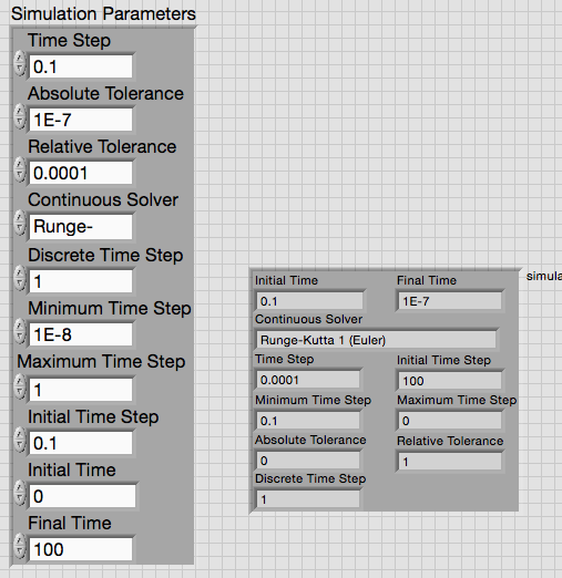
I think that the cluster command may be part of the problem. The full error message states: "the initial time of the simulation cannot be greater or equal to the last time." The values in the cluster of Simulations settings on the front panel do not violate this condition.
However, I have created an indicator by popping up on the simulation of the ODE Solver.vi connector pane settings input terminal. When I wire to show that sees the Solver VI, I get last time< initial="">
Try to replace your control of parameters of Simulation with a created from the entrance of the ODE Solver.
Lynn
-
Why the outputs that are grouped in a waveform chart in a loop of Simulation show distortion?
Is anyone know why the outputs that are grouped in a graphic waveform distortion to see the Simulation loop unlike these forms of output wave that are placed individually in each waveform graph Microsoft Graph?
-
PtbyPt filter FIR in the Loop Simulation
Hello
Currently, I am trying to simulate the power in my engine when I apply a voltage step for 20 MS for that I intend to use a FIR filter in the control and simulation module that simulates the other parts of the engine.
However, I have found that the FIR filter seems to be strange behavior. When I change the order of Runge-Kutta 1 simulation to 2 of Runge-Kutta it effects the output of the filter FIR PtbyPt VI. The two attached images show how the results of the convolution of the IR and the tension, the FIR outside the simulation loop filter and FIR filter in a loop using Runge-Kutta 1 are the same. However, the second image shows that the FIR filter in the loop simulation Runge-Kutta 2, has a different answer.
Why does this happen? As I understand it, the type of simulation should have little effect on the application of a FIR filter based on pt by pt. I have not changed the timestep or other parts of the simulation. I want to use a simulation of order higher than for other parts of Runge-Kutta 1 would be insufficient for the simulation.
I'm using LabVIEW 2011 SP1.
Thank you
Rhys
When you try to use RK-2 or higher order, the screw that dumped you inside the control and the Simulation loop, by default, they will all run in the "minor" time steps too. In your case, 'two times' which means the VI will be executed each time step.
To properly configure these screws, you must "right click" on the VI and select "Installation of the Sub - VI node. This will bring to a Setup page that the second half you will choose in 'Type of Simulation Subvi execution' to 'remove' the "Include minor steps" box and press OK. When you do this, the Sub - VI will be annotated on the upper right with blue 'C' and when you run, it should provide a similar result as RK-1.
Note that in this dialog box, you can also select discreet, which, in many cases, it is the right selection for 'discrete' systems
I hope this helps...
-
Synchronize loops control and Simulation
When simulate control with adjustment of the LV systems and Simulation loops, I often have several loops running at different speeds. For example, I have a loop PWM works at 20 kHz, a loop running at 100 kHz data acquisition and a control loop to running at 10 kHz. How can I synchronize all these loops so that they stay on the same time basis? Of course, the main time base must be at least as fast as the fastest simulation loop.
I tried to synchronize all the loops at 1 kHz clock (I'm on Windows), but each loop runs a period by beat of clock (for example my 20 kHz loop count progressive 50us by beat of clock, my number of loop 100 kHz up to 10 by beating of clock, etc.). I need all the loops to be synchronized in a main time base so the simulation time is identical in each loop, but each loop will be executed at a different pace.
Any thoughts?
Hello
A quick suggestion - why you cannot run three systems in a single simulation loop, but have different sampling frequencies for the blocks for each system?
Your system is fully digital, or a mixture of continuous and digital - we can simplify things if you can convert in discrete time.
Hope this helps,
Andy Clegg
-
Increase control of the façade of a trigger button in the Loop Simulation
I want the 'Index' control to automatically increment when you press the OK button. It works very well. However, the control of the Index gets automatically incremented whenever the VI is started and when you press the Stop button. Even if the box Structure is wired with a constant False (which means that it must never be run), control of the Index is still incremented.
Is there a bug when using local variables within the structures of the case in the Simulation loop? This does not occur when you use a while loop.
I think that since a loop of Simulation has no shift registers, you will need to use a feedback node.
I have NO experience using simulation loops, just trying to help.

See the example attached to see what I mean.
-
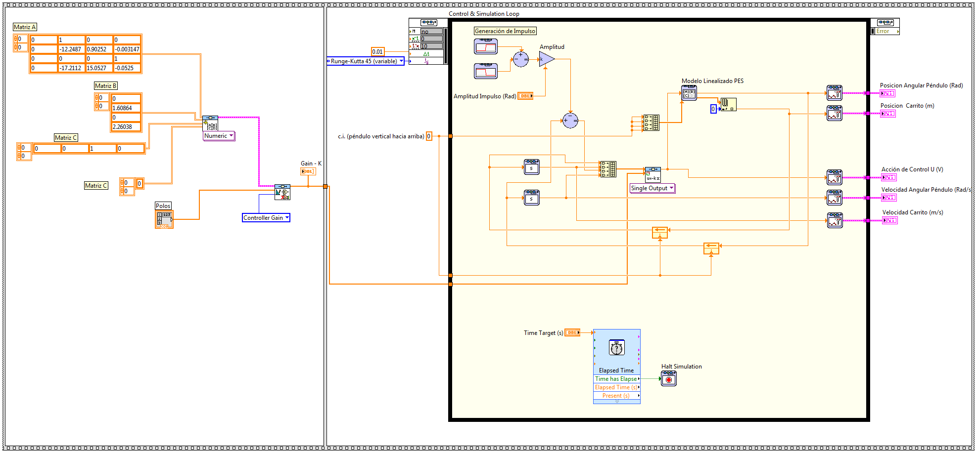
I wonder if there is someone who could give me a helping hand with a simulation, that I'm running. I am trying to simulate the behavior of a system modeled as state space and do a controller using different techniques, but I'm having problems and can't advance too far... It seems that the simulation loop gets on a sort of infinite loop and he can't stop but I don't know what else to do... Left, I enclose the block diagram of one of the screws simulation I so could someone there watching.
It is a model of an inverted pendulum system and a cart modeled as state space and try to see the behavior of a placement of pole due to a pulse controller imput. Initially, I would check a model no length I have but it was too weird so I replaced it with the linear model to the point of unstable equilibrium, but the VI stuck too then I felt motivated to post here.
(I tried to join the extract by using the code below, image generatin capture tool so you can download and run the code, but it's my first time using this tool, so hopefully it will work well... I created the extract .png and gasket here using insert image... that is right? )
In the Simulation node, shift registers could have different behavior which would explain the problem that you run in. So, if you want to 'break' the feedback node (which in general, you shouldn't need to do), then use the block of 'memory '. He'll try to behave as you would expect.
In addition, you can look at the example of shipment for the linear simulation:
C:\Program Files (x 86) \National Instruments\LabVIEW 2014\examples\Control and Simulation\Case Studies\Mechatronics\Inverted Pendulum\Linear inverted pendulum Simulation.vi
Or non-linear simulation:
C:\Program Files (x 86) \National Instruments\LabVIEW 2014\examples\Control and Simulation\Case Studies\Mechatronics\Cart-Pole\CDEx Cart-pole control and Simulation.vi
as a reference for your example. You notice even reuse the animation for your application.
-
Order to internal model with cRIO, synchronization of time loop
Hello
I work with control design Simulation & toolkit and I want to implement an internal model control to a real-time target. I want to implement my simulation (as an attachment) to the real target (cRIO-9024 OR cRIO-9112). I removed the transfer function of the process, I broke the line and I added my input/output of the cRIO modules. I put a 1ms, Euler ode solver step size and synchronize the time loop. Unfortunately it does not work properly. The loop decreased the speed a lot and I can't get 1 ms response time and, finally, a good answer for my system. This means that I can not 1ms response for loop? What is the problem of the computer, windows or hardware real-time or software? Simple or I did something wrong? All the advice you will enjoy.
Kind regards
Kamil
Maybe you are looking for
-
My iMAC seems to be overheating.
On a regular basis, my iMac seems to be overheating. What should I do?
-
Tortoise SVN and Assembly of LabVIEW
I know that Tortoise subversion is not officially supported by NEITHER but I also know that some of you use it however to manage your source code control. We have started using it about half a year ago and are usually happy to have. The problem I rea
-
LabVIEW RT on the objectives of the third party
LabVIEW RT can be used with any target that runs VxWorks or Pharlap? We have the software developed in LabVIEW RT for the controllers of RIO and the PSC as the functioning of the entire installation - with an integrated web and ftp - server, developm
-
Windows Media Center won't play movies or videos.
Windows Media Center problems began with the shifting of the wmc vedeos vedios. now his habit get worse let me do something hardy
-
Console for ISR4331 USB driver
I can't find the USB Console driver for router ISR 4331 on the CISCO Web site. Anyone has any ideas how to find the download?