Slope of digital triggering NI SCOPE
I have a problem, try to use a digital triggering with a USB-5133 digitizer. I use NO-scope (3.5) and C. My software doesn't seem to be able to change the slope of the trigger (using niScope_ConfigureTriggerDigital()). There is no problem if I use an analog trigger.
The problem is not related to my code. I see the same behavior with the NOR-SCOPE Soft Front Panel (version 2.9). In this application, if I connect the trigger PFI 1 entry and select digital triggering, then the selection of the slope has no effect. However, by selecting briefly "edge" trigger, change of slope in this mode and back to digital triggering, I find that the trigger is now working according to the slope in the edge, trigger mode.
Although niScope_ConfigureTriggerEdge() seems to work o.k. (using an analog input) and is not niScope_ConfigureTriggerDigital(), the following sequence does not provide a work around:
niScope_ConfigureTriggerEdge (...);
niScope_ConfigureTriggerDigital (...);
The entrance of IFP 1 seems OK, even though at the start I had been feeding it straight V CMOS 5 door. Adding a separator line at the entrance to the tensions between 0 and 2.8 V had no effect on the behavior.
Hello Bmetz,
It is a known problem that has been fixed in version 3.5.1 OR-scope. You can download and install the update through the page drivers and updates here:http://joule.ni.com/nidu/cds/fn/p/sn/n23:3465.40/lang/en
You will find a list of bug fixes in the readme, including the following:
123308: Fixed problem
with incompatible trigger when to change the edge of triggering on the NC
USB-5132/5133.
Hope this helps,
Jennifer O.
Product Support Engineer: scanners high speed
Tags: NI Products
Similar Questions
-
generate a digital triggering out CH1 (low and high) for the USB-5133
Hello
I would like to generate a digital triggering on the USB 5133 CH1, is this possible? I tried with the PFI 1 successfully but the output is only 3.5 v and I need to 5V, because this trigger signal goes to a box of pulse generates a signal, which is received by the CH0 on the USB-5133. This configuration works on the 5102 OR but because of the treatment, I am obliged to try a new device.
Channel 0 and 1 are only entries then you will not be able to use them to generate a signal. All of our products current digitizer that are recommended for new designs use 3.3V CMOS logic levels for PFI lines in output mode. Your best bet to generate a digital triggering 5V would be to use an external buffer that can accept 3.3V CMOS levels as an input, but is under voltage of 5V. Here are some that might work for you, but there are many others: http://www.onsemi.com/PowerSolutions/product.do?id=M74VHC1GT126DT1G adding a buffer in line with the trigger signal will add delay, so you will need to ensure that it is acceptable for your application.
Hope this helps,
-Matt
-
simulateneous of analog and digital triggering
Hello
I have an experience that is very similar to this announcement:
As in the display, I need trigger out of logic AND low frequency (3 Hz) and a signal of high frequency (100 Hz). However, my experience is different because my low-frequency signal is an analog of entry (AI0) and I need experience to trigger off each edge of the signal change high frequency, while the analog input is high. To do this, I created a trigger to HAVE that starts a counter whose state high and low are similar to that of my analog input signal. I then export the output event from the meter to a port (PFI8) and pass this signal and the other signal high frequency through a door AND as in the posting linked above.
So far, everything works. I've included a VI that is just this part.
However, I then connect the output of this gate AND a PFI0 port and use it as a digital triggering to read an AI0, 1 channel. When I perform this final step, my whole system stops working, but gives no error. To troubleshoot, I measured the output of the meter to the port of PFI8 has stopped working and the port of PFI8 remains in the low state. For some reason any when I add the channel HAVE additional (AI0 or AI1, whatever) with digital trigger (PFI0), everything grinds to stop. I have also included the VI for this case.
Any ideas?
Thank you very much!
Hi Jared,
I use indeed a door AND external as described in the thread. Further research actually led me to discover that "you can't have two analog input tasks at the same time" of this thread:
So I had to build a circuit to convert my analog signal into TTL signals (for the release). I then AND'ed the two signals in the same was as described in the thread mentioned above.
-Clinton
-
digital triggering of stop/start of analog data acquisition
I want to use a signal from a digital line to start and stop analog data acquisition. The signal can change levels several times during a race of the VI so I have to start and stop several times data acquisition and store each session data in a different file.
I tried to play with the following screw: digital triggering of break, DigitalStartandStopTrigger and ContAcq_DigTrig. None of them doesn't seem to work for my configuration. I also do continuous data acquisition so I can't use a reference. I use PCI 6259 DAQ.
I used the "P0" pins rather than PFI pin on the grid BNC-2090. I know... stupid enough.
-
Outbreak of the AO tasks with digital triggering
I'm triggering an analog using a digital triggering (PFI0) task on a NOR-6343 (USB), but don't see the behavior desired of my VI (see screenshot).
* When I shoot digital triggering (digitalTrigger = False), the AO signals appear planned (except that... they do not fire).
* When I turn on the trigger (digitalTrigger = True), however, there is no signal on the channels of the AO.
* I tried two different sources: PFI0 and the clock internal (set both rising edge). For the PFI0 channel, I connected a function with a wave generator square 5 v (the PFI0 had a slow rise... time "I think I could solve this problem by adding a small circuit of buffering). However, I expect it should work correctly using the internal clock as a trigger.
What's wrong with my code / setup?
A few follow-up questions:
* This will trigger the installation program not start indicator AO once? Or the trigger will cause the task to start whenever the finished AO signal and the trigger goes high? (I wish that it behaves like the latter)
* Just to check: the response rate of the AO task to the digital trigger should be of the order of 1 MHz?Hello kllurie,
What do you use the trigger for? The way you have the task to put in place now, it will run continuously until you press the STOP button and ignore any input trigger. If you want to be able to have the task to complete and start over with a digital triggering, you make the task two finishes and Retriggerable. You can configure the task to be finished by replacing the constant continuous samples on the Timing.vi with finished samples and giving him a number of samples to be taken before stopping. Then you can do the task Retriggerable using the property trigger DAQmx node and choosing Start > more > Retriggerable sometime before the Start.vi.
As to what it should be used as your relaxation, you'll want something with a fast rise time (so that it is detected as a numerical advantage) and is not as fast as the sample clock. If you use the sample as your trigger clock, there would be essentially no difference between your redeclenchables task and a continuous. It would end the collection of samples and then immediately redeclenchee.
Let me know if that answers your questions!
-
Digital triggering PCI-6024E problem
In my view, the PCI-6024E is intended to support that integrates digital triggering. However, I get the following message if poster every time I try a digital triggering:
"Error-200452 is produced in property Node DAQmx trigger (arg 1) in DAQmx Start Trigger (PowerPlay) .vi:1-> relaxing test.vi.
Possible reasons:
Vital statistics: Property specified is not supported by the device or is not applicable to the task.
Property: Start.TrigType
"Task name: _unnamedTask<245>"
I'm on 8.9 DAQmx and Labview 8.6.
I've included the simple vi, I tried to test a digital triggering with where I made some stupid mistakes.
Thank you!
Hey Ptuinluff,
Have a look here for information and an example on how to use another subsystem to allow the trigger to start. Let me know if you have any questions.
John S
Technical sales engineer
National Instruments
-
Problem - edges of digital triggering slows down during the fast rotations
Hi all. I have problem to understand. I want to measure the pressure with two strain gages on 90 degrees (NI 9237 half bridge II) and I engine with metal plate on it with 52 teeth (gear) to measure on each tooth of the strain. For the rotation, I use NI 9401 digital input.
I need for example 1000 samples from the first digital edge to the second. (on the metal plate). I try to start trigger. In slow speed (turn around with the hand) of the metal plate, everything is OK. But if I turn around the metal plate digital fast triggers edges slows down. During a cycle on the metal plate on the cost of slow speed me 52 digital edges 1000 sampels by edge (metal plate is with 52 teeth), but rely on fast speed on me 25 edges. This problem is sync of the digital inputs and the analog inputs. I made the example with DAqmx Vi express. I've implemented on digital imput and then count me in each tooth regardless of speed and everything is OK, but when I buid trigger of strain on the edges of quick release rotation speed slows down.
Can someone help me with this?
Thanks before.
So you're collecting samples from 1000 to 10000 samples per second. Which takes 100 Ms. If your triggering edges occur more quickly than the interval of 100 ms, some of them will be missed. If you run faster than a cycle all 5.2 seconds your gear plate with 52 teeth, some triggers will be produced before the end of the previous data collection.
What is the fastest speed that you will not sping palte metal?
Lynn
-
How to start collecting data through digital triggering entry user GOLD
Hello
I have a vi with which I would like to collect data. It is configured to start to perceive when the start trigger is detected, which works perfectly, but I would also create a user can start the process of data collection by pressing a button instead of apply the trigger. I am at a loss on how to do it. I thought that the structure of the event would work well; However, the relaxation has no Boolean value I can associate it with. If that were the case, I could then perform a logical comparison between the trigger and the button to determine if the collection of data should begin.
So, how can I represent a trigger activated as a Boolean value? Or is there a better way to reach my goal?
I think I can make things clearer by expressing in linear programming that it is, I'm trying to achieve:
If (trigger == true: button == true) {}
begin to collect data
}
I have attached my vi where someone feels useful.
Hello
You're right, 6229 USB is certainly not compatible with NO-Sync. However, you should be able to do with the DAQmx driver functions.
If I understand correctly, you want to generate a graph of your analog input and have this file based on a triggered event entry. A line using PFI will not work for this particular function, but you can create a task digital input instead and pass the thread to a D e/s instead of a PFI line line. You can then use for/no-write the analog input file using a case structure depending on the State of the digital line.
I hope this helps! Let me know if you have any other questions.
-
Generate the AO with digital triggering
Hello, I have a problem, generate a continuous waveform (custom channels multlisample) when a TTL - as 5V 0V trigger is applied to PFI0. The problem is that synchronization source is running continuously, when the digital voltage line is connected I don't have to keep a single waveform sent, as opposed to a regeneration of the same waveform.
I have worked with some conditional loops, but nothing works, is there a solution that can provide two triggers (one for a pulse train) and then for the digital falling edge (on 0V) which can allow the regeneration of the writing of the AO?
Thank you
DB.
Hey DB,.
I recommend using a pause trigger. This will allow you to exit when a certain level of TTL is high (or low) and not when the opposite is true. Here is an example that illustrates the break trigger using property DAQmx nodes.
You need to change the time by continuous for this example sample clock, but also to change the data to be written to fit your application.
You can leave the writing of the initial value in the analog output channel if you wish, or you can delete the original entry, start and stop functions DAQmx. Either will work.
Best,
-
Digital triggering Vs software relaxation.
I'm running a DAQ USB-FS1608 of MCC to measure multiple channels of analog voltage. I also have a digital camera from a regulator of frequency MTS 407 TTL. Inside my VI, I read a signal rising TTL of the Multilateral trading system, send a signal to activate the digital output, then I start my acquisition of data. 1 Hz, it would be better to control my digital output, (which sends a command to execute for the Multilateral trading system, which then operates a hydraulic piston) with a hardware trigger?
Yes, you must connect the signal you want as digital input on the TRIG_IN channel, and then keep the same wiring to your digital output.
-
Digital triggering PFI on a cDAQ-9188
I use a Campell data recorder to send a pulse of 5mV to my daq to trigger the recording of some accelerometers. I also have the code to stop acquisition when another pulse is sent, the code has currently a predefined sampling time how I would change.
Thank you very much
I'm glad that it worked. You get with the other examples?
There is a slight difference between the former and the latter. The one you posted just checks for the trigger of the judgment in software rather than in hardware, so you will be limited to verification of the digital line as you take more analog samples. If it works for you, but then that's fine.
One thing I would recommend is a stop button, so you can stop the loop if you want, without having to give up the program. It will ensure that you clear resources etc.
-
Series two E shared digital triggering
Can it be converted into LabVIEW 2012?
Yes. You need to post in the Forum Conversion of Version as I mentioned above.
You seemed to find your other file you want to convert.
Version conversion Board was created to prevent disorder in the ordinary Council of LabVIEW for people who are in need of converted files.
-
DAQmx generating triggers TTL and triggered read it
I am running LabVIEW 2013 on a Windows 7 PC and I use a card PCI-6251 DAQ with a BNC-2110.
For my application, I need to generate triggers TTL (for example, with a frequency of 1 Hz). At the same time, I need to run data to HAVE which is triggered by the same TTL signal.
So far I managed to implement the TTL square signal properly with a spot of meter output - I can see the triggers on a scope. I also have a task of entry of HAVE and included a digital triggering. He works in part, and I have a few questions:
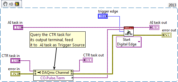
- The physical channel of triggering TTL is set to ctr0. This seems to be associated with the PFI12. I rather would specify the terminals directly in my program - is it possible? The ctr0 is not labeled directly on the BNC-2110.
- The task of IT is triggered by the PFI0. I connect a cable from PFI12 to PFI0. Is this really necessary? The task of the AI can be triggered internally for the same counter? My external hardware must be triggered with the same signal as the acquisition. So far, my solution seems to be the only way I can make it work.
- Digital triggering for the task to HAVE it is configured to 'rising edge' trigger. However, when I run the task to HAVE it continuously in a loop, it seems that it is triggered Alternatively edge bearish and bullish. I checked this by connecting the meter to exit on PFI12 directly to the input string for the task to HAVE it, and I observe that the periodic square wave changes sign. Why is this? It is a problem for my application - I need to be able to always trigger on this same Board.
Thank you very much for your help.
hmalissa:
You can query programmatically for the pulse of a task of the meter output terminal using a property DAQmx channel node. Here is an excerpt. Just save the image and drag the file into a LabVIEW block diagrom and turns it into code. You do not have to use this as a Subvi, controls & indicators are just there to identify the task who is who.
Bob: interesting experience. But to help future readers to draw the erroneous conclusion, I just would insist that a timed hardware task still * fact * produce much more repeatable calendar timed sample a software task programmed in a software loop. Example of Bob is not address the regularity of the individual sample interval, just by comparing the driver DAQmx or MS Windows timer is more sensitive (and repeatable) to marking the end of an interval of 1000 msec.
-Kevin P
-
Error 50103 - simultaneous analog Vout and wine with start of analog triggering
Hello
I'm stuck error 50103. I looked on the Web site of NOR and worked through the 7 cases and think that my problem is the 6 case - although I'm not sure - and have no idea how to fix this. Basically, what I would do is out my signal and have receive side save after it passes through a noisy channel. To start, I have attached a trigger control so that the transmission or recording start before the input trigger exceeds a certain value (in my case, 3V).
Could someone please look at my code (attached, called 'Optical_DPPM_V3.vi')) and try to give me an indication as to what I'm doing wrong? Thank you!
Furthermore, I use examples of OR that I have also included in the .zip for reference file.
SP
P.S. hardware: LabView 8.2, NI PCI-6070E
Hi gt3000,.
Thanks for your reply. I actually solved the problem I called one of your offices directly and spoke with someone last night.
Indeed, the problem was "case 6" as it is stated on the page you gave. "." When I spole with one of your colleagues, I was directed to an example that does most of what I wanted. If anyone is interested, you can follow this path to find:
Help--> find examples--> material input and output--> DAQmx--> synchronization--> multifunction--> multi-function Synch AI - AO.vi
It seems that the trick is to use an internal digital triggering to synchronize the CLK for VI and VO.
If people are interested, I can send my final code around for a differential pulse modulator, triggered by an external analog voltage which the receiver registers and stores the values in a worksheet. My next goal is actually write the code for the receiver to demodulate information... here go us!
Thanks again,
SP
-
How can I more easily generate a pulse of digital output of finite length?
Hello
I need to open and close the two pneumatic valves using a TTL output (without load current or the output power) using a PCI-6280 or PCI-6601. The valves must open almost simultaneously and closing after different amounts of time elapsed (millisecond level timing, maybe 100 microseconds-level timing at worst). My current plan is as follows:
-Create a task with two digital outputs (type of waveform) and another task with a counter that generates a frequency set by the user (I know I can use the generator frequencies on one of these cards, but I would have preferred a counter - the best selection of frequencies).
-Wire the output of the counter at the entrance to clock two digital outputs.
-Output of the meter is digitally triggered by another digital channel which I use to control if the pulse goes out. Through its counter node, it is programmed to be redeclenchables.
-Two digital waveforms are drafted who have both consist of unique active high pulse (i.e. signals go ' down (for the amount of time user-defined) - low ".")
-These signals is written to their respective ports and their tasks have started, as is the task of the meter.
-Whenever the user wants to open taps, digital triggering is sent up and then back to low (this can be done with synchronization software, because it is not exactly when the fire valves). Whenever the user wants the valves open for a different period, different digital waveforms are generated and written in the buffers of the digital output channels.
My problem is that it looks like a lot of effort for me to go and I wonder if there is a much simpler solution, that I don't know everything. You can program a computer to produce a pulse of finite length? Is there a faster way to program a digital output for that channel?
Thanks to anyone who responds to their help.
It is certainly instructive. Thank you.
The thing is, I have only six total counters to work with and I have a lot of time to do things. To use these solutions, I would need to use 4 or 6 account counters required to my needs.also that I would need to synchronize their departures.
Overall, I stick to my method for now - less system resources and synchronization can be don by using the same meter of finished output clock and not to use a trigger to all.
Once again, thank you for your help so far.
Maybe you are looking for
-
What type of cable/port is called also where I can buy one?
Please link me the website where they have cable!
-
I have no idea what I did, one minute, I was reviewing this specific menu, the next he was gone. I can still access the version of the sidebar and my bookmarks bar is still there, but the menu real disappeared. Close and restart Firefox did not work,
-
Qosmio G30 - Question on the Raid driver
Do I really need this driver to use RAID functions? If its set in BIOS, what makes the pilot actually do? outside you give health statistics? See you soon
-
Need drivers for the Sidewinder Precision Pro X 03-57540
I NEED DRIVERS FOR THE SIDEWINDER PRECISION PRO XO3-57540 JOY STICK.
-
A few questions on System32 and registry
What are the dangers of editing the registry? If done correctly, this could happen, I heard that it can destory a computer, IS it true? And what are the dangers of a modification or deletion of System32?