Error in Data Acquisition
Hello
I use the DAQ assistant for data acquisition and display the data in a graphical indicator. My camera is 6221 PCI and DAQ card is CBS 6221.Now that my problem is after you run the program after that 3 - 4 times it starts to give me an error message which says as follows:
"Attempted to read samples that are no longer available. The requested sample was already available, but has since been replaced.
Increase in the size of buffer, most frequently the reading of data or by specifying a fixed number of samples to read instead of reading all available samples would correct the problem. »
My acquisition mode is continuous and I'm giving samples to read a value 1000 (which I suppose than the size of buffer) and my sampling rate is 1kHz.Now if I change my samples to read a value of 10000 the chart becomes too noisy. And also at some point, the program crashes.
I increased the sampling rate of 10K and my samples read had a value of 100, but still there was the error message.
Any suggestion would be appreciated to eb.
Thnaks
Hello
I was able to run this code without errors. Your error is caused by this: map The DAQ is written samples to the RAM to the sampling frequency (1 K). Your loop is pulling 100 sample chuncks. If your loop can not read at least 1000 samples in a second, the buffer eventually replaces unread samples. Your reference time loop to make sure that it is excuting at least 10 times per second. Use execution of highlight to ensure that write measure filw VI is opening and closing properly.
If you change the sampling frequency, you don't want to use the same samples to read as the sampling frequency. To read samples must always be less than the sampling frequency to allow faster than the card written loop data. But the other stuff in the loop are causing which slows down the execution of the overal loop time, if she were to run frequently. Make the samples to read about 80% of the sampling rate will give a good report.
Tags: NI Software
Similar Questions
-
LabVIEW statechart module of data acquisition error external trigger
I have a 2 loop vi is the acquisition of data of a data acquisition instrument loop and the second is a loop to run my statechart of. I would like to respond to an error in device of acquisition data if it occurs in transition out of my current state in my diagram States-transitions and enable management of custom unique business mistakes. My States-transitions diagram is synchronous and send it external trigger.vi funciton will not work with it. How to achieve this? In addition, there is some confusion about this literature in http://zone.ni.com/reference/en-XX/help/372103F-01/lvscconcepts/sc_c_callervi/ at the bottom of the page it saidNote sending triggers for synchronous charts is optional. If you do send triggers, LabVIEW sends the NULL trigger for transitions. If you send a synchronous statechart triggers, you can send these triggers to the caller VI. »
Is it possible to do this and if so how with the synchronous statechart?
Thank you, it should work for me
-
DAQmx data acquisition with persistent error of nyquist
Hi, I created a multi channel data acquisition vi (accelerometer 2 and 1 sound pressure) using models for producer. The vi is attached. Thanks to labview 2011. I get the error of nyquist (2 enclosed) when you make a bandpass filter between 50 to 5000Hz. This happens despite having put my sampling rate to 22050Hz. When I checked the output of wave I noticed that the signal has a dt 1 s. The text output to check the result. I could not understand how this is so since I had set the sample rate to 22 k Hz. Any help will be much appreciated. Thank you.
I would do something like that. You must calculate the dt of the set (with the recipricol) sampling frequency and use to initialize the shift registers. This way you only need to change 1 constant if you need to change your sample rate.

-
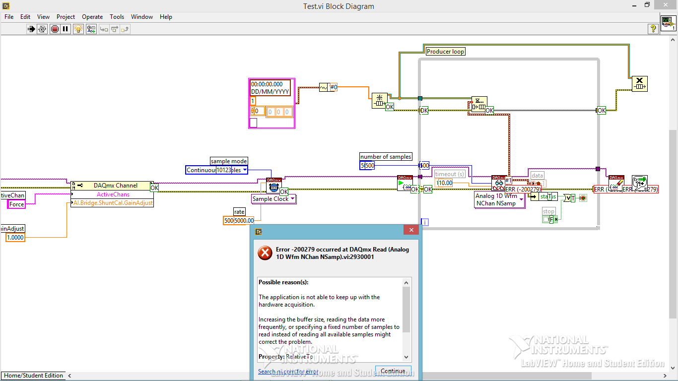
Code error-200279 for data acquisition
Hi all
I am trying to build a small program of data acquisition, but I get a 200279 error telling me to increase the buffertime. What I am doing wrong?
Andersson wrote:
No, you're right. I don't get the error, I turn off highlight execution.
It seems so. I did not understand why he would come with an error during the audit of the code with the bulb. It seems like what I discovered on www.ni, one can avoid the error of initialization of certain data for the chart.
Not sure if I got it 100% correct however. Here is the link:
http://digital.NI.com/public.nsf/allkb/A647A1BE3DA8336786257AAA0066B45B
I don't have any other loop in the installer. I'm sorry for the confusion with the name 'producer loop. It's the only loop in the code, I deleted the rest to refine the error.
Is the conclusion that the program is good? Or do I have to do something to remove the error?
The table has nothing to do with your error. It's strictly highlight execution.
When you configure a continuous sampling, start the collection of data at a given flow rate. It is so big a configuration of the buffer. There is an article that tells how much room it is exactly, but for the sake of argument, let's say 10 seconds worth of data. In normal execution, your code runs pretty quickly that she is able to empty the buffer as soon as the data are acquired. But when you enable execution of climax, your VI slows down to a crawl so that he can show that you step by step what is happening on each wire. Your data acquisition always occurs in the background. Execution of idle is to take much longer that data are acquired. Within one or more loop iterations, you have filled the buffer and get the error message.
You cannot use point culminating performance when you use a device of data acquisition in this way (or VISA ports either) where data are sent continuously at a speed that is independent of speed, the code is executed.
-
Data acquisition reading incorrect when you use a loop
Hello
I wrote a simple VI (00, 01, 10, and 11) output to a circuit connected with 4 resistors. Based on what value the ciruit receives, it passes current through a particular resistance. It is again entered in Labview and traced.
The problem is when I send a particular value (i.e the 00, 01 and 10 and 11) and get that back, it's okay. But when I send and receive the consectively connected via the loop counter, they are incorrect (not synchronized with the number of the loop).
I made sure that circuit works very well. It has something to do with the loop synnchronization, reset, value compensation, etc. can be.
Please Guide...
Change your DAQ assistant that reads to be 1 sample on request.
Right now it is set for continuous samples. And 10 samples at 10 Hz. Then it runs and starts. The next iteration, you send a new digital out, but the wait for 4 seconds. When you read again, you get the next 10 samples that are put into the buffer of data acquisition, but now 40 samples have actually entered the DAQ buffer. In time your DAQ buffer will be finally complete and raise an error. In the meantime, you will continually read data continues to become more tainted by the iteration.
-
data acquisition won't taste at the specified rate
Material: C - DAQ 9178, AI 9239, inside a servo and an encoder potentiometer module
Setup: I use the 9239 to measure the angular position of my servo and encoder of trees by streaming came pressure pot of the servo and my encoder. I put the sampling frequency on the DAQmx - Schedule VI to 100 Hz.
Problem: I don't think that my DAQ is sampling data at 100 Hz because my VI registers more than 10 000 data points for a 10 second test. In addition, every time I have save my data in a text file, the vector of time my test data resets after a number of iterations.
To debug, I tried the following configuration:
I've defined the sampling frequency of 100 Hz (or is that s/s?), the samples per channel (size of buffer for continuous mode) at 2000 samples, number of samples per channel up to 10 and loop milliseconds timer on my VI at 10 m accordingly, data acquisition would send 100 samples per second (or 1 sample every 10 ms) on my PC buffer (which could store 20 X that amount). Then LabVIEW would read up to 10 samples per loop iteration (which is itself ~ 100 Hz) and work with these 10 samples inside the loop. However, since the loop is operating close to the sampling frequency of data acquisition, then LV should only work with 1 sample each iteration of the loop (100 Hz / 100 Hz)-not the 10-sample-max that I specified.
However, I stumbled on "error-200279: the application is not able to cope with the acquisition of material" when I ran the program. Why?
My code and materials should be easily able to cope with data acquisition - at least the way I put it in place
This whole situation wondered my fundamental understanding of data acquisition timing, so I would really appreciate an explanation of exactly how to deliver DAQmx uses data synchronization, why my DAQ sample at 100 Hz, and how can I fix the calendar specified by the user.
Thank you!
aeroAggie wrote:
The C - DAQ 9178 there some minimum sampling rate I will not meet?
It's actually the 9239 that limit your sampling rate. Read the data sheeton page 5 there's available data rates. In short, your data rate allowed is 50kS/s / n, where is goes from 1 to 31. 50 k/31 gives you 1.6kS / s. So, it's the minimum sampling frequency that can be used.
-
data acquisition stops automatically
I want to stop assistant DAQ automatically after a period of time, so I created this VI.
When I start the program, it work and after reaching the value of time specific 50, the graphical indicator ' looks like "stop, but wait after 9999 second, the graphical indicator suddenly see a lot of data that seems to be taken for the 9999 seconds, what is happening? After that, it gives an error saying:
Possible reasons:
Attempted to read samples that are no longer available. The requested sample was already available, but has since been replaced.
Increase in the size of buffer, most frequently the reading of data or by specifying a fixed number of samples to read instead of reading all available samples would correct the problem.
Property: RelativeTo
Corresponding value: current playback Position
Property: Offset
Corresponding value: 0Task name: _unnamedTask<100>
Data acquisition cannot be stopped like that?

Thank you
Not quite. Like this.

-
LeCroy Waverunner 640Zi - Data Acquisition
Hello... I'm trying to set up my oscilloscope waverunner with LabVIEW SignalExpress for data acquisition.
I took the steps so far:
1 pulse generator hooked to scope of signal generation
2 USB scope to the installed computer with LabView
3 downloaded lecroyscope driver 3.2.9 - x 64
I turn on the scope and plug in the USB to the computer and SignalExpress begins.
a. start by using data acquisition
b. Add step/aquire signal / IVI aquire / IVI brought aquire
c. create new IVI session... resources descriptor (I choose my USB device ' USB0::0x05FF:0 x 1023: 2812N61507:INSTR '), I select the right driver (lcscope), and I do not click enable simulation data, press ok
d. I still receive configuration errorse. did the research... some forum said goto MAX, find drivers and uncheck the Cache and the exchange of check
f. attempt to initialize... always get config errors.
g. return to MAX... change to simulate with specific driver.
h. initialization works... NO errors, BUT no data are acquired.
Help, please!
Hello
Sorry to jump in if I was out of the country for a while and am still catching things in my office.
I think you are looking for someone to say yes, "you can connect to the scope with NOR-MAX and VISA, and here's how interactive tool do"
A few things:
LabVIEW for XStream extended driver is the right one. It works with all the TeledyneLeCroy Windows based scopes.
As I see has already been noted. (I'll give Kudos soon), the scope of application must be configured to use interface USBTMC. To do this, go to the drop down Utitlites on the scope menu and select "utilities configuration... '. "in the tabs that appear at the bottom of the screen, select the 'Remote' tab and make sure that the interface type is set to USBTMC. This will also show you the VISA resource (I see it in the title of the image of VISA interactive tool indicated in a previous post).
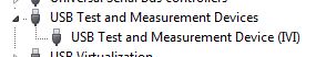
Once this field is selected, the PC should detect the USB connection and install the device. (you can see in your device manager as a Test of USB and the measurement device):
Once this is done, you can then enter the NOT-MAX and it will detect and display resources. You can now communicate with the device:
If you have problems, do not hesitate to give me a call and I'm happy to walk through it over the phone.
Kind regards
Leonard Brown
Technical sales engineer
Teledyne LeCroy
1-800-553-2769 -
Data acquisition tool NOR-DAQmx with Matlab R2012a
Hello
I'm trying to control NI USB-6211 of Matlab 2012 using NOR-DAQmx Data Acquisition tool:
http://zone.NI.com/DevZone/CDA/tut/p/ID/3005
I'm working on win7 64 bit. And I see the device AND Measurement & Automation Explorer.
The tool does not work: DAQ_Demo_Browser do nothing. And I got the error "unexpected or unbalanced parenthesis or support" of AcqNUpdates_nonUI.m
What is the problem?
Thank you and best regards,
Arthur Shulkin
Hi Arthur,.
Tools OR DAQmx for Acquisition of data with the Software Inc. MATLAB® from The Mathworks, supports up to the 2008 version of the MATLAB® software. In order to use our products DAQ Multifunction with MATLAB® software, you could get back to 2008 or earlier, or instead use the Data Acquisition Toolbox provided by The Mathworks, Inc.
Another option would be to import your ".m" files in a node MathScript in LabVIEW and use the functions of NOR-DAQmx everything in the LabVIEW development environment. For more information on the Module LabVIEW MathScript, you can consult the information available on this link:
Inside of the LabVIEW MathScript RT Module
MATLAB® is a registered trademark of The MathWorks, Inc.
Katie
-
Input module of data acquisition can be read by two or more LabVIEW vi at the same time % 3F
I use the DAQ palette in LabVIEW to read the virtual channels of the input data acquisition module. I've done several VI who read many entries of three modules of simulations. The problem appears when I run two or more VI´s reading entries from the same virtual module (for example. first.VI module 1 input ai0 and second.VI bed ai0 entry module 1 bed), when this happens the next errors are shown:
Error-50103
Platform AND Services: The specified resource is reserved. The operation could not be performed as indicated.
and
Error-200022
Resource requested by this task has already been reserved by another task.
It's worrying because I want to get the DAQ chassis and some modules, but if this problem is present with physical equipment my application may be unnecessary. This means that entry module only can be read once at the time?
I m using global variables in each Subvi to share data with main VI, however, I found the solution in a different way... I just changed to single channel and dbl sample playback mode, so I Don t need to clean up the task of reading in my subVI´s, the zeros isn´t problem here, and the six subVI´s work at the same time!
Thanks for the tips!
-
the relay control data acquisition
I am creating a vi that controls (press and release) several relay using a USB 6501 data acquisition. This should be a task relativily easy but I get flumoxed by errors. I tried to use the examples, but I get an error telling me that I need to use the mode of generation 1 sample (on request). Help, please
Sure. The easiest way is to have a DAQmx writing followed by a function of delay, followed by another entry, followed by another period. Simply plug the error links in order to control the flow of data. However, the VI would be insensitive so you can use a state machine or function elapsed time so that the VI can be stopped without waiting for waiting for him at the end.
-
2 channels of AI on a data acquisition with the range of different sensitivity
This vi is based on the 'new project' state machine on the home screen at the start of LV.
A time loop is parallel to the main loop of the state machine, shown in the picture.
It works continuously until you press the Exit button.
The problem seems to be in start this... > read >... stop start > read >... stop along the error line.
The reason for this clumsy arrangement power is measured voltages are in two lines of different sensitivity.
The shunt voltage is small and needs-. 2 to the range of V.2. The load voltage is greater and 09:50 V range is good.
In the initializing state, two separate vi 'create a channel' have been used to specify the range of voltage to the physical channel. The corresponding tasks are sent via via local variables.
DAQmx errors happen randomly, sometimes the first iteration, sometimes the 50th.
I tried to disable one or the other start > read > stop for the shunt voltage or load.
I tried replacing them with the DAQ assistant.
I tried various DAQmx vi: "wait" and "accomplishment of the tasks by resource cancel selected".
But error-50103 "specify resource is reserved" keeps popping up.
Is it possible to create two tasks on the device even when they are not used at the same time?
The only reason is to measure in two voltage ranges.
Win 7 Pro 64-bit
2014 LV database
Data acquisition equipment: USB-6210
Thank you.
This has been discussed many times. Do NOT use separate tasks. You can use different ranges for different channels with a single task. Just wire the task from one channel to another channel to create task.
You also use local variables when they are certainly not needed.
-
Acquisition of data stops at data acquisition
Hello
See the attached VI. Data acquisition acquires data without problem for a few minutes, and then suddenly the event structure does nothing but the timeout. I'm deliberately ignore the 200279 error that is generated when two triggers are too close to each other, because I want to just ignore these triggers, but perhaps which also prevents tasks at a certain time? I also tried to start and stop the task again in the case of timeout events, but it does not help (it causes an error). Is there a way to prevent either the DAQ card (I use the box USB-6251) of the judgment of the data collection or a better way to ignore triggers that are too close together?
I hope that I am making some sense here :-)
Thank you
Jeremy
Jeremy,
Thanks for letting me know about the 99% CPU usage. It is definitely the cause of your accident and can be avoided by putting a funtion waiting with maybe 10 milliseconds in your timing loop. However, if you want to keep avoiding strict with no node blocking, you will need to restructure your VI to use the Express VI of time elapsed since the range of Timing. You will find examples of the use of this VI in detailed at the bottom help.
Hope this helps, have a great weekend!
-
Problem of reliability data acquisition PXI-4071
Hello
I'm having a problem of reliability using my 4071 Pxi digitizer mode.
I have a number of tests that use the SMU-6363 (usually configured for DC) analog output to provide a stimulus for our own device, which has a number of a/d converters. We use the PXI system for calibration and testing.
1. I select a voltage ranging from tensions.
2. program the PXI-6363 to drive this tension
3 TIME about 10ms to settle. Note there no discrete capacitors or resistors in the circuit. Everything is parasitic and would generally be under the nF mark and less than 10 ohms
3. configure and Initiate() acquisition of data with the PXI-4071. In general, I use a sample rate of 1000 s/s and get about 30 samples (worth 30 ms). Activation is immediate and I used the default a queue time, 0, set the time and it doesn't seem to make a difference.
4. measure the voltage with the CDA. For debugging purposes I have sometimes made twice once before calling Initiate() and once after. The after is normal. The time required to measure the ADC is shorter than the acquisition time, but regardless of stimulation by the SMU-6363 is constant
5. extract the waveform.
6. the average waveform and compare the value of ADC measured by applying tolerances etc.
Here's the problem: it works well most of the time. But only 0.1% of the time (1 on an acquisition of 1000), I get 8-12 samples that are close to 0. It sounds like a problem of time settling (on the surface), but no matter the amount of wait time data, I always get this behavior. Not only that, but the tension before the call to Initiate() in height CDA, it always confirms that the motor voltage is already set to the programmed value. Nevertheless the acquisition presents near data 0.
So far our independent ADC always reports the expected before and during acquisition (100%) voltage. It's like the DMM input is disconnected during the acquisition during a period of time, because we have confirmed that the voltage is already present prior to the acquisition (component can). I have no errors the insider or FetchWaveForm calls. I still have all my samples. And 99.9% of the time that everything works as expected.
The DMM and ADC are connected to the same point and both are referenced to ground, and as I said before only the parasitic capacitance and resistance (cable). We use a matrix of switching (PXI-2530 (b) to make these connections. We almost always use 51/2 digits and 10V range for data acquisition.
Hello
I thought about it and was going to repost but am distracted.
The device with the ADC also has a mux and switches the mux to an internal node. It only switches when measuring and is open at other times. There is a race condition where the acquisition starts too early and maintains the acquisition after that the switch is open. Unfortunately I don't have the option to trigger.
I forgot the internal mux that I had designed the test years ago and I did some updates to improve the stability of the test. That's why we start the ADC measurement when acquiring.
I just added a routine to reject samples below a threshold
-
Why data acquisition in an executable collect fewer samples?
Hello
I have LV2012 on Windows and SMU-6341 map in PXI chassis.
I have a task for the acquisition of data on I-1 on my monstrous application. Well, to get to the point, I have here a case where the task of data acquisition starts, waiting 20ms, reads all available samples and puts an end to the task. For the parameters see the piece attached. Then, the collected data is plotted on a waveform graph. Usually about 200 samples are taken in the case of data acquisition. Then loops shown sequence, until certain conditions are met.
Unfortunately a problem occurs when I deploy a rack application (exe) on a production PC some 600 miles away from me.

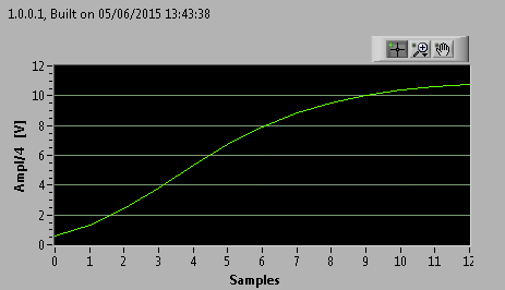
This is an example of what I get on my development PC (LV and runtime give similar results):
This is an example of what I get on the production of exe PC (13 iterations, bad luck
 ):
):It totally looks like the data acquisition task mentioned seizes one sample to an iteration of the loop.
I enclose a noodle dragged out of the main program. I'm about to test the version of this noodle on the production of PC in a few hours, but I would like to hear all the ideas that emerge.
Thanks in advance!
cubz wrote: from my experience, the continuous 'Samples' mode does not stop when the buffer is full. The loop of 4 seconds (with 10 k samples/s in the sample buffer 40 k)-that is to say samples how finished works IMO.
If the buffer is filled in continuous mode of the samples, you will get an error. I'm sure it's something you don't want. In this example, you have provided, you really should have finished samples and has said the acquisition of data to read samples of N. It is the only way to ensure you get all the data you want.
In regards to your differences between development and executable, the executable file tends to only not nearly as happening (Debug stuff for the most part), so it tends to run faster. If you're depending on a software clock, anything can happen (having a ton of little or no data). That is why we say you use the clock machine and get the number of samples that you actually want.


Maybe you are looking for
-
Safari is locked on my MacBook Pro. 268 3 d error
Safari iis locked up on my MacBook Pro. It shows the message * your Mac has been blocked * # 268 3 error call the 1-844-412-6929. Etc, etc, etc. How can I get rid of this. Safari does not. I would appreciate help. Thank you.
-
Hello, just turned on HP mini 110 1030NR running Windows XP Home edition of the husband. Purchased in 2009, very limited use, not programs never added. Nothing new at all in setting up the plant. The computer starts correctly, but the first moveme
-
relationship between this workstation and the controller main failled
I have this problem, one to help me pliz
-
Tyring to download Windows 7 upgrade advisor, it does not work on my PC
Download Windows 7 Upgrade Advisor, bit, it won't work
-
It seems that XPS Document Viewer is not backward compatible after installing the Vista SP2. When a document is signed digitally with Vista SP2, the signature cannot be seen with Windows XP, the viewer of XPS documents. First of all, let me say: If t