Trigger by using PCI-6233
What is the best way to trigger an entry to start of data acquisition when the test unit is in analog motion? I use a card of acquisition data PCI-6233. The input voltage is generated by a linear transducer.
Thank you
Gerry-
Your card doesn't support a trigger analog input. Your card must support a digital signal of 10 VDC, but if you are worried the voltage is high so that it triggers, then you can use a voltage divider to reduce the strain of your relaxation. You could try to get edge in case your switch is wired backwards.
If the signal you are measuring is a floating source and you use differential measurement, hold on to the positive terminal to your terminal block 1 Terminal and the negative terminal to Terminal 2 and use a wire between terminals 2 and 3. It is the best way to measure a floating source.
If the signal is floating and you're not really worried about the introduction of ground loops, you could plug it as unique reference ended. That is the positive wire going to Terminal 1 and the negative terminal goes on Terminal 3.
You will use these same configurations if the source is grounded. Again, differential is the best configuration to avoid Earth loops.
For your relaxation, you relate to the positive terminal of the source of 10 VDC to Terminal 13 and the negative terminal of the Terminal 14.
I hope this helps!
Thank you
Sean
Tags: NI Software
Similar Questions
-
Can I use with NI PCI-6233 of SCXI signal conditioning
The title says it all. I wonder if I can use my unit with the NI PCI-6233 industrial data acquisition card and if so what cable should I use between the chassi and map of SCXI signal conditioning?
Hello Tsthorsell,
This feature is not plausible. This can also be verified by simulating the chassis and unity, the 6233 OR cannot be selected as the transmitter/receiver.
Best regards
M Ali
Technical sales engineer
National Instruments
-
Can I use PCI-MIO-16-4 with windows 7
I'm still on windows XP, but will be upgrading to windows 7. Can I still use PCI-MIO-16-4.
I guess not. I don't see where he works with DAQmx and the NOR-DAQ (now called traditional DAQ) is not compatible with Windows 7.
-
How can I activate several tensions trigger on the PCI-6221 using NOR-DAQmx?
I use the card to make an acquisition of data simple PCI-6221. The idea is to allow three different analogue voltages trigger the State of data acquisition. I currently put code in place for a trigger voltage but I'm not sure what to do to add two additional trigger voltages. Any ideas?
Thank you.
Hi capncane,
The 6221 is not able to do an analog trigger so DAQmxCfgAnlgEdgeStartTrig will not work for your card. Is your relaxation a digital signal? If so what kind of logic level is? If it's TTL, you can use the PFI lines. If this isn't the case, you need to trigger as I mentioned in my previous post.
-
Calendar synchronized with Diuble pulse using PCI-6601
Hello
I'm trying to run a PIV of Labview 8.5.1 system using a PCI-6601 map at the exit of the signals for the laser and the camera.
This requires a line for the camera, one for the FPS (first removal of pulse) and one for the Q-switch.
The difficulty is in the need of a double pulse on the Q-switch for mode double frame PIV.
The distribution box that I use is not one NOR one and I don't have access to 3 outputs four against, otherwise, quite simply, I would use a BNC t with two pulses slightly staggered junction.
I have access to a BNC-2110 timing box, but I think it is not compatible with the PCI-6601 and have no funds to buy a BNC-2121 right now.
I managed to create a double pulse by using one of the counters with a finite number of impulses set to 2 and then stop the task, then run this in a timed loop.
However, it is then based on the software, which is not precise enough for the application, and I can't figure out how to get the timed loop to run from the time of 20 MHz of 6601 map base.
I could be missing something obvious here, or perhaps is more annoying? I'm fairly new to DAQmx.
Thanks in advance
Joe
Dominic makes a good point about the operating system, but really the best solution is to use the hardware timing when possible.
I have set up an example that shows how you can implement different sets of impulses finished using the calendar of the Commission. It requires the use of two meters, but then again a generation of impulses finished the fact (on the 6601).
Communities: Generate several Cycles pulse finished using two countersAlternatively, if you have another signal that you want to use to trigger each set of pulses (rather than to specify a rate so that they occur as in the example above), counters on a 6601 are redeclenchables then you can use the external signal to trigger the generation over time and time again without having to stop the task in the software.
Best regards
John
-
Control correctly 3 heartbeats at 3 meters of material using PCI-6601
Hello
It is a sequel to a previous post
http://forums.NI.com/NI/board/message?board.ID=40&message.ID=7914#M7914
as for control a PIV of LabVIEW rig using a PCI-6601.
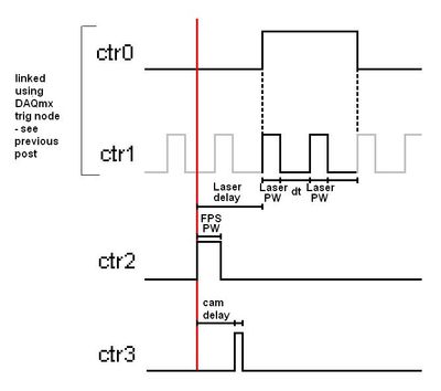
The task requires the production of pulses in three outings of the counter. The Q-switch laser, to a double pulse (which is resolved in the previous post), while the other two are simple impulses. It is important to be able to control with precision the difference in width and pulse between pulses.
As far as I understand, I need to configure timers to start and then run from the material without other software entry
I tried using the "initial deadline" option when creating counter channels, but it is very innaccurate (probably that uses the software?). Similarly, using the lag in call loops option does not produce a time delay (and requires the use of a meter as a synchronization source, leaving me without enough counters)
Below is a basic diagram time for a single iteration, keeping in mind that this must be repeated in the range of 100-1000 Hz, approximate pulse width (PW) would be 2 microseconds and delays in the region of 500 microseconds.
I need to be able to define
delay of Cam and laser delay with precision (and the pulse widths must be easy in theory)
Sorry if I forgot something important and thanks for your help
Kind regards
Joe
Hi again Joe,
We could just trigger all out 2 meter (pulse FPS which seems to start the acquisition as a whole).
CTR 2 would be a continuous pulse generation (at the rate we want to re - triggered the entire process).
CTR 3 would be a unique generation of impulses of retriggeralbe, with an initial delay.
CTR 0 and 1 are a bit difficult in the context of the rest of the application.
I think that the suggestion I posted in the previous thread should work fine by CTR 0 triggered with an initial delay.
Otherwise, we could do an output meter redeclenchables finished, but if I remember correctly there are specific behaviour with the initial delay of the finished products redeclenchables counter that could give us unexpected results (I would find the link but ni.com seems to be down at the moment).
I won't be back in the office until next week so I don't have any material to try this, but I think that should help you get started in the right direction at the moment. The desired behavior should be achievable, but it might take a programming smart everything for line lift correctly.
Using a trigger external or not should not affect the programming of the double line impulse which is the most difficult aspect of the application.
-John
-
Generation of pulses using PCI-1428 to CC1
My laboratory uses an external signal generator to generate a pulse to trigger a line scan camera and continuous acquisition of image acquisition card. The lab has just acquired a new camera and unfortunately I can not use the external trigger on the camera connection. I understand that PCI-1428 cannot external signal to a line of camera control. I tried to generate a pulse of MAX, but he won't let me have a pulse with less than 24 US pulse width.
So first, I was wondering if there is a way to generate a pulse with less than 24 US of MAX pulse width.
And if this is not possible, is there a way to generate a pulse of Labview similar to he'S generation.vi of pulse but he sent via the CC lines for the order? Also, how can I program it to make the generated pulse is sent as soon as the frame grabber receives / detects the start of the external signal?
Thanks for your help.

Don't know who did the file of the camera, but the 1428 can generate pulses with a period of 40ns on CC1 (a time base internal 50 MHz is used at the moment of high/low pulse). You can use NI Camera File Generator to modify existing camera files:
http://sine.NI.com/NIPs/CDs/view/p/lang/en/NID/14207
It has good documentation for how to configure the settings of the pulse. If you still have problems, you can view the camera file, let me know what you're trying to use the mode, and which calendar you want pulse and I was able to address the issue, but I recommend trying OR Camera File Generator first... make a backup of your file to camera to keep your original autour.
Hope that helps,
Brad
-
Outbreak of several digital lines of a single window using PCI 6353
Hello
I use a PCI 6353 to control a laser for a PIV system. The laser requires 4 pulses (F1, F2, T1, T2) on different channels. It would be easy using 4 counters on the Board, but I also need to trigger the camera. The card has a lot of output digital, so I thought I could use 2 meters and four digital outputs.
I thought that, by setting the pulse counter from 0 at a time duration between F1 and T1 and triggering a rising edge and T1 F1 a front down using output internal), I would be able to solve the problem. However, the system I cannot trigger the two lines of the same internal output. I don't know why. I have attached two vi, one for a single channel that works very well and the other with two channels. I am also attaching a diagram of approximate time of my proposed solution.
I am not absolutely put on this format, so if this is not possible and you have another solution, please let me know. Accuracy is the key here, the widths of pulse being about 1 microsecond and the intervals between F1 and Q1 being approximately 10 microseconds, so I think the hardware timing is essential. However, I'm not quite clear on interact it with the digital pulses and counters.
Kind regards
Joe
Hey Joe,
All the lines that you want to use for quick time ARE on the 6353 must be in the same spot. Unfortunately, you can't start or clock several lines independently.
That said, I think that the simplest solution would be to simply create a waveform suitable for generating all 6 signals with. You should be able to clock up to 10 MHz, which gives you 100 ns resolution. If you need 1 us resolution, then you could get by synchronizing the c to 1 Mhz. While you could technically use a combination of counters and to get what you need, it should not be necessary in your case. All you need is a single task with the waveform appropriate to generate your desired signals.
Best regards
-
Integrate the external trigger into camera (PCI-1424)
Hi all
I use a PCI 1424 acquisition card to take the image of a Kodak "camera".
Currently, I put the camera on a continuous mode - in which the camera give me frames one after one. I am able to 'snap' or 'capture' images of MAX with the help of the camera file. I can write a simple VI for 'break' a single image in LabVIEW.
Now, I want to go to the single camera viewing mode. In this mode, the unit will display a single image to a trigger signal (the rising edge of a singal TTL).
I wrote a short program for parallel port allows to send this signal triggered at the camera. The increase in power to the camera temporialy, I know that the camera captures an image.
However, the question is how can I nathalie caron this image?
What I do now, is to select 'snap' a picture to the MAX and allow a delay of 10 sec. After you click on the snap, I'll go to LabVIEW and send the trigger signal to the camera.
However, in MAX, I altenativley had a black and white image that is of the Court a false image.
does anyone know the reason?
and how do I integrate the VI trigger in the captuire VI image, so that I can finish the task of single capture inside a VI?
There is a sample VI "Grab.vi triggered" in which user can set waiting time and other properties for IMAQ1394, but I do not know how to PCI1424
Thank you very much.
Dear John,
I have attached this VI.
LabVIEW 7.1
Framegrabber: PCI 1424
Trigger the camera: after set us the camera in mode single shot (by rider material), I just need to send a signal of TTL and the camera will trigger in the front of this signal. So I schedule a pulse to the OID 0 pins at this TTL signal output.
-
Using PCI-8532 with NOR-DNET 1.6.6 / NOR-DNET 2.0.2
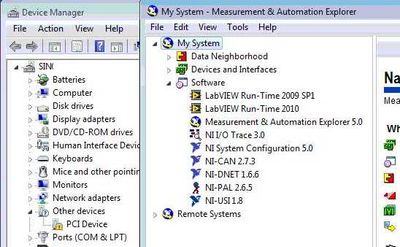
I have a PC with the following configuration test set-up:
- Card PCI-8532 DeviceNet
- Windows 7 Enterprise, SP 1
- LabVIEW 2010 Runtime
- NOR-DNET 1.6.6 with MAX 5.0
- No environment of LabVIEW Development
- PCI-8532 isn't available in MAX and Windows Device Manager indicates the card as "PCI Device" with an exclamation mark.
Here is a screenshot of Windows and MAX Device Manager:
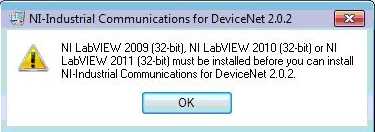
I can't install the NOR-Industrial communications for DeviceNet 2.0.2 on this computer because I get the following error:
Well, I have two questions
- How can I install and use the PCI-8532 and see with NOR-DNET 1.6.6? If this is not possible:
- How can I create an executable file on my system (portable) development with LabVIEW 2010 or 2011 LabVIEW and run this executable on the test set-up. I currently have on my development system:
- Professional 2010 LabVIEW and LabVIEW 2011
- NOR-DNET 1.6.6
- No hardware OR at all
- I have to install the NOR-Industrial Communications for DeviceNet 2.0.2 on my laptop (my development system)
- This will interfere with my current NOR-DNET 1.6.6 and then I select which driver to use at compile time
Thank you
Nick
Nick HY,
No, it is defenitely not a replacement yet and I will work with our Web Department who make clearer on our web page.
The development of the new API is pretty well done, but based on your feedback, we are planning to improve compatibility, so you can for example use the old APi 1.6.x and the new APi of 8532 on the same machine, so you can use the old and the new material on this same machine. Which would be important for you?
For the moment we intend not to allow only one type of material on the same machine to save you development time. Let me know what you think.
To clarify the situation today: The InCOM for Devicenet component is not part of LabVIEW. It's just a very simple means of communication with the I/o variables and blocks of function for the MS. The driver should install fine even without installed LV. The error message is quite a Bug on our side, and the solution would be to use the Builder installer LV to create a new installer that can install 2.0.x Incom Dnet driver without having installed Lv.
And today, you should be able to have the 1.6.x both pilot 2.0.x in parallel and use the API 1.6.x with old boards yonce and the variable approach of IO 2.0.x with your new Board of Directors.
I'll keep this post updated as soon as we have a stable Beta available I'll post something.
DirkW
-
Meter very low frequency using PCI-MIO-16-4
Hello
I am trying to use a card PCI-MIO-16-4 with BNC-2090 to CI FREQ. Because the sometimes less than 1 Hz frequency of our leaders, or even no time measurement taken, the vi program always shows "Error-200527" and tells me that the min frequency must be greater than 1,192 Hz. If this card cannot measure very low (even zero) frequency in time measurement taken? If it is possible, how? Could you show me some examples? Thank you very much.
Damien
What method of measure do you use to measure your rate? You are able to assign at least 0 (default) to 2 that would be the rounded version of 1,192. Alternatively, you can try to use one of the other methods to measure and see if that helps. All these values can be set with the channel to create VI.
-
The card using PCI-GPIB hangs the system (Windows 7)
Hello
I am running Labview 11.0 (32-bit) on Windows 7 (64-bit) computer and card PCI-GPIB to communicate with instruments.
Can I use GPIB to send commands to the device, but when I used "Measure and Automation" and analysis of the instruments he runs right first time, but if I scan again the system crashes completely (no reaction to any seizure).
Same thing happens if I use I/O Assistant VI, I can get a response from the instrument and on the second call, the system hangs. Yet, I can send as many orders without any problem, so the source is in the reading stage.
The PCI-GPIB card worked perfectly well for years on another computer running Windows XP.
Someone already had this problem and what can be the source of it?
I had a similar problem, but I just found out that the motherboard was not good...
Try in another computer... Optionally, you can uninstall and install back the NI 488 drivers. 2...
-Germain
-
Using PCI and GPIB-Enet drivers set
We need to use a PCI and Enet GPIB controller at the same time under Solaris 9.
Is this always the case that it not there no driver unified for the PCI GPIB card and the Ethernet GPIB for Solaris (Solaris 9) controller, as shown in your post on the forum of April 2004 (pfrogers and JoshuaP)?
If there is no unified driver, is it possible to install two drivers in different directories, and then compile a program that will access both devices having carefully he use different files for header C and libraries, according to what access controller? It seems to me, the answer will always be no, because your API GPIB function calls will have the same name between the two controllers, so there is no way to specify what (PCI or Enet version) function to call.
Thank you.
Hello
Thank you for your message. Yes, it's always the case that there is no unified driver for the PCI-GPIB card and controller ENET/GPIB for Solaris 9. You are also right in your assumption that you will not be able to compile a program that will allow you to access these two drivers in different directories. I apologize for the inconvinience this may cause you.
Have a great day!
Kind regards
Todd v.
-
Laptop crashes when you use PCI-6132 and a box of magma
Hello
I use a laptop with a magmabox (Cardbus connection) to accommodate a card DAQ of NOR-PCI-6132. When I'm data acquisition the laptop freezes sometimes and has to be restarted. Anyone who is familiar with such a problem?
I did not have this problem when the DAQ card is in an office with a regular PCI slot. So, I guess that the problem is related to the magmabox.
Nick Wagner
Hi Nick,
The problem could very well be linked to the magmabox, but before that can be determined, I need more information about your hardware. I already know about the PCI-6132, but I don't know anything about your laptop or magmabox cardbus connection. Can you tell me the manufacturer and the model number of your laptop and the magmabox so I can check their specifications? Thank you.
Best wishes
Wallace F.
-
I use the PCI-6723 card and I am trying to produce a model of waveform using the analog output channel. The wave consists of 5 different voltage levels. The main problem is that the first 4 voltage levels are supposed to have 926 microseconds time intervals and the time interval the last voltage level is supposed to be 1,296 milliseconds. In addition, the waveform must be triggered on the trailing edge of a sample clock of 200 Hz with a 0.1% Duty Cycle. Is it still possible? If so, any help would be greatly appreciated. Thanks in advance!
Here is what I currently have, but it does not fulfill my purpose.
 int32   written;
    float64 data[5] = {-0.23, 0.38, 1.12, 1.78, 0.10};  //volts
    //long  time[5] = {  926,  926,  926,  926, 1296};  //microseconds

    // DAQmx Configure Clock
    DAQmxErrChk (DAQmxCreateTask("",&taskHandleFRQ));
    DAQmxErrChk (DAQmxCreateCOPulseChanFreq(taskHandleFRQ,"Dev3/ctr0","",DAQmx_Val_Hz,DAQmx_Val_Low,0,200,0.001));
    DAQmxErrChk (DAQmxCfgImplicitTiming(taskHandleFRQ,DAQmx_Val_ContSamps,1));

    // DAQmx Start Code
    DAQmxErrChk (DAQmxStartTask(taskHandleFRQ));

    // DAQmx Configure Code
    DAQmxErrChk (DAQmxCreateTask("",&taskHandle));
    DAQmxErrChk (DAQmxCreateAOVoltageChan(taskHandle,"Dev3/ao0","",-10.0,10.0,DAQmx_Val_Volts,NULL));
    DAQmxErrChk (DAQmxCfgSampClkTiming(taskHandle,"/Dev3/Ctr0Out",1000.0,DAQmx_Val_Falling,DAQmx_Val_ContSamps,5));

    // DAQmx Write Code
    DAQmxErrChk (DAQmxWriteAnalogF64(taskHandle,5,0,10.0,DAQmx_Val_GroupByChannel,data,&written,NULL));

    // DAQmx Start Code
    DAQmxErrChk (DAQmxStartTask(taskHandle));
Bingo. This code seems to work much better. Looks like I had to reduce my number of samples per 1 to fit the waveform desired in 5 milliseconds of the sample clock delay.
However, if someone knows a better way to achieve these results, I am open to all ideas.
void CDevDlg::OnRdr1e1()
{
    float64     data[4000];
    float64     volt[5] = {-0.23, 0.38, 1.12, 1.78, 0.10};  //volts
    int x=0,d;

    for(int v=0; v<4; v++)
    {
        for(d=0; d<741; d++)
        {
            data[x++] = volt[v];
        }
    }
    for(d=0; d<1036; d++)
    {
        data[x++] = volt[4];
    }

    // DAQmx Configure Clock
    DAQmxErrChk (DAQmxCreateTask("",&taskHandleFRQ));
    DAQmxErrChk (DAQmxCreateCOPulseChanFreq(taskHandleFRQ,"Dev3/ctr0","",DAQmx_Val_Hz,DAQmx_Val_Low,0,200,0.001));
    DAQmxErrChk (DAQmxCfgImplicitTiming(taskHandleFRQ,DAQmx_Val_ContSamps,800000));

    // DAQmx Start Code
    DAQmxErrChk (DAQmxStartTask(taskHandleFRQ));

    // DAQmx Configure Code
    DAQmxErrChk (DAQmxCreateTask("",&taskHandle));
    DAQmxErrChk (DAQmxCreateAOVoltageChan(taskHandle,"Dev3/ao0","",-0.5,2.0,DAQmx_Val_Volts,NULL));
    DAQmxErrChk (DAQmxCfgSampClkTiming(taskHandle,"",800000,DAQmx_Val_Rising,DAQmx_Val_ContSamps,4000));
    DAQmxErrChk (DAQmxCfgDigEdgeStartTrig(taskHandle,"/Dev3/Ctr0Out",DAQmx_Val_Falling));

    // DAQmx Write Code
    DAQmxErrChk (DAQmxWriteAnalogF64(taskHandle,4000,1,10.0,DAQmx_Val_GroupByChannel,data,NULL,NULL));
}
Maybe you are looking for
-
My child is send and receive the iMessages someone that I do not agree. How can I block this person in a way that can not unlock my child? I'm not completely disable iMessage.
-
A new router through Talktalk and since then my printer Wireless does not connect. It shows on my chromebook as this has already been added as a printer of cloud, but blue light wireless flashes. Not had any problems before this that he was that we
-
Origin of the panel inside the Panel, not postioning on positioning screen
Is there an execution property for the form/Panel that you can use to check the origin of the group. When I say original, I am referring to the coordinates 0,0 used in the LEFT and TOP offsets, used by the controls. I found the FP. PanelBounds and
-
I was faced with a problem very irritating lately, when my computer is suddenly trolling when I do any sort of typing. I've seen other posts on this subject, but none of them seem to apply because they are all about the specific programs only - what
-
Updated 2015.3 AE and first does not
I've just updated (Windows 10).After effects does not start.First gives an error at the start screen and crashes.Accident similarly to the splash screen for Media Encoder.I already rebooted etc etc...PS and I are working properly.Looks like is a matt