Generation of pulses using PCI-1428 to CC1
My laboratory uses an external signal generator to generate a pulse to trigger a line scan camera and continuous acquisition of image acquisition card. The lab has just acquired a new camera and unfortunately I can not use the external trigger on the camera connection. I understand that PCI-1428 cannot external signal to a line of camera control. I tried to generate a pulse of MAX, but he won't let me have a pulse with less than 24 US pulse width.
So first, I was wondering if there is a way to generate a pulse with less than 24 US of MAX pulse width.
And if this is not possible, is there a way to generate a pulse of Labview similar to he'S generation.vi of pulse but he sent via the CC lines for the order? Also, how can I program it to make the generated pulse is sent as soon as the frame grabber receives / detects the start of the external signal?
Thanks for your help.
Don't know who did the file of the camera, but the 1428 can generate pulses with a period of 40ns on CC1 (a time base internal 50 MHz is used at the moment of high/low pulse). You can use NI Camera File Generator to modify existing camera files:
http://sine.NI.com/NIPs/CDs/view/p/lang/en/NID/14207
It has good documentation for how to configure the settings of the pulse. If you still have problems, you can view the camera file, let me know what you're trying to use the mode, and which calendar you want pulse and I was able to address the issue, but I recommend trying OR Camera File Generator first... make a backup of your file to camera to keep your original autour.
Hope that helps,
Brad
Tags: NI Hardware
Similar Questions
-
Calendar synchronized with Diuble pulse using PCI-6601
Hello
I'm trying to run a PIV of Labview 8.5.1 system using a PCI-6601 map at the exit of the signals for the laser and the camera.
This requires a line for the camera, one for the FPS (first removal of pulse) and one for the Q-switch.
The difficulty is in the need of a double pulse on the Q-switch for mode double frame PIV.
The distribution box that I use is not one NOR one and I don't have access to 3 outputs four against, otherwise, quite simply, I would use a BNC t with two pulses slightly staggered junction.
I have access to a BNC-2110 timing box, but I think it is not compatible with the PCI-6601 and have no funds to buy a BNC-2121 right now.
I managed to create a double pulse by using one of the counters with a finite number of impulses set to 2 and then stop the task, then run this in a timed loop.
However, it is then based on the software, which is not precise enough for the application, and I can't figure out how to get the timed loop to run from the time of 20 MHz of 6601 map base.
I could be missing something obvious here, or perhaps is more annoying? I'm fairly new to DAQmx.
Thanks in advance
Joe
Dominic makes a good point about the operating system, but really the best solution is to use the hardware timing when possible.
I have set up an example that shows how you can implement different sets of impulses finished using the calendar of the Commission. It requires the use of two meters, but then again a generation of impulses finished the fact (on the 6601).
Communities: Generate several Cycles pulse finished using two countersAlternatively, if you have another signal that you want to use to trigger each set of pulses (rather than to specify a rate so that they occur as in the example above), counters on a 6601 are redeclenchables then you can use the external signal to trigger the generation over time and time again without having to stop the task in the software.
Best regards
John
-
Generation of pulses using NOR-PXI-5421 FGen
Hello Sir/Madam,
Question:
We use the Funktiongenerator NOR-PXI-5421 and just want to generate a pulse, because it can be done in almost all cheap Funktiongenerator.
Unfortunately, I can't find a way to tell the Funktiongenerator to generate a pulse. I can generate Singals as I like, but don't know how to generate a single pulse.
Perhaps you have a program that gives me this opportunity.
Thank you for your support.
Hi Jens,
You can try to use the Council 5421 scripts. The following examples of LabVIEW: "Fgen Arb Script.vi" or 'Fgen switch between Waveforms.vi' use of script to generate signals, you can create a script that generates a single DC pulse of high level in the same way.
I hope this information helps you.
Best regards
Blase
-
Digital and analog generation and acquisition using USB-6251
Hi all
I have to actually synchronize a 6251, USB and USB 6366 Board. I have a vi, which is good that now I am able to use the 6366 as the master and as slave 6251, attached tie. The master generates a digital trigger for (generation synchronization) pulse and the acquisition of the signals on both cards, analog signal ramp and acquires signals. The slave acquires only a series of signals after outbreak.
I want to have the 6251 as master and as slave 6366. The vi attached the other way around as I mentioned above. When I try to use the 6251 as the master, I get an error asking me to specify the clock source (I did the material and some changes in the program as well, as export properly 6251 at 6366 clock).
Thank you
SANJU
Thanks for your reply jonathon,
But in your code below, I coudnt get the Outpput internal PCI-6251/ctrl0...
but I hardwaired the o/p (PFI 12) meter... .and generated a signal meter on this port, I used that as the clock...
Thank you
SANJU
-
Can I use PCI-MIO-16-4 with windows 7
I'm still on windows XP, but will be upgrading to windows 7. Can I still use PCI-MIO-16-4.
I guess not. I don't see where he works with DAQmx and the NOR-DAQ (now called traditional DAQ) is not compatible with Windows 7.
-
Generation of digital signals through external trigger pulse on PCI 6251
Sir I want by NI 6251 because I read it has the ability to generate and acquire digital signals on port 0. I want to know that can I generate external clock wave triggering (providing impulses to a line on the acquisition of data)?
Hi Ali211,
Yes, you can use a source of sample for the digital input/output clock external clock. You can connect the external clock source to one of the lines PFI (PFI0-PFI15) and specify the source clock sample like this outer line of PFI.
There are some shipping DAQmx examples that you can start with. Find the examples by clicking Help > find examples in LabVIEW.
DAQmx continually reading digital channel with External Clock
DAQmx channel External digital writing Clock
Hope this helps.
Chris G
-
Synchronization of the generation of pulses and digital dashboard with a PCI-6229
Hello
Your Board of the M series has only 2 meters - that's why you can not perform 3 tasks. Here's to
least another idea you might consider.
Review the task where you want to count the edges of a particular signal increase. You can probably
make line in wiring up a digital port 0 and making a DI task based on "change detection".
You can then simply keep track of how many samples have been taken that will give you the
as much as the edges with a meter spot.
-Kevin P
-
niHSDIO dynamic generation and Acquisition using LV configure Trigger VI
Hello!
My experience is limited within the environment of digital programming; Nevertheless, I have worked on this problem for a few days and would appreciate some comments if possible.
I am trying simply to generate and acquire a duty cycle of 50% of 8 MHz TTL pulse train on a PIN DIO of the PCI-6541 and acquire back from the signal on another axis of DIO. I have a connector corresponding to the embedded 6541 VHDCI connector which of course the generation and acquisition DIO welded pins to provide a loopback effect.
In short, I use the niHSDIO configure Trigger VI (instance--> start Trig: SW), niHSDIO send software Edge Trigger VI and write Named Waveform VI (instance--> data: 1 D U32) in the generation section. For the section of the acquisition, in short, I use the VI of waveform Fetch niHSDIO (instance--> single record: WDT).
I see results in the waveform acquired showing the generated and acquired digital TTL pulse on the respective DIO pins train, but I can't seem to get my 8 MHz frequency requirement. In addition, the lower part of the assignment of pin DIO, more frequency. Unfortunately, due to the configuration system required, I have confined myself to pin 12 DIO for the generation of digital pulses. Even with a 50 MHz clock frequency, I'm ~ 6 kHz of frequency acquired max. I looked at changing the parameters of the wave form VI named write, but it is not possible because the VI call a library function node. I also tried to generate a waveform of 8 MHz through a VI of generator of digital model, but I do not believe, you can trigger on generated waveforms? It seems that you must generate data using a simple loop to as a counter and sending the result to the waveform VI named write. Are there other ways I can simply generate and acquire a digital signal of TTL of 8 MHz (no external connection)?
In any case, any kind of feedback would be greatly appreciated.
Thanks in advance for your time.
Dan
Dan,
Sorry about the nomenclature. I usually use 0 x or 0 b for indication of radix, it is not necessarily a kind of standard, just what I used in my old days of the Assembly.
Looks like you have a knowledge about the data. Basically the material is just save in DRAM an array of words of 32 bits, with each bit corresponds to a data channel and each element being generated to the sampling clock rate you enter to your vi. Everything else is just easy data manipulation or usage. The interleaving method is just as I like to create a toggle model. You can easily do a loop with an inverter and feedback node or use on the construction in screws to signal generation. In addition, you can use the software digital waveform editor or control panel test to generate the county or toggle modes.
Give us an update when you enter the laboratory and let us know if you encounter any other disorder.
-
Control correctly 3 heartbeats at 3 meters of material using PCI-6601
Hello
It is a sequel to a previous post
http://forums.NI.com/NI/board/message?board.ID=40&message.ID=7914#M7914
as for control a PIV of LabVIEW rig using a PCI-6601.
The task requires the production of pulses in three outings of the counter. The Q-switch laser, to a double pulse (which is resolved in the previous post), while the other two are simple impulses. It is important to be able to control with precision the difference in width and pulse between pulses.
As far as I understand, I need to configure timers to start and then run from the material without other software entry
I tried using the "initial deadline" option when creating counter channels, but it is very innaccurate (probably that uses the software?). Similarly, using the lag in call loops option does not produce a time delay (and requires the use of a meter as a synchronization source, leaving me without enough counters)
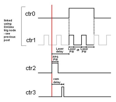
Below is a basic diagram time for a single iteration, keeping in mind that this must be repeated in the range of 100-1000 Hz, approximate pulse width (PW) would be 2 microseconds and delays in the region of 500 microseconds.
I need to be able to define
delay of Cam and laser delay with precision (and the pulse widths must be easy in theory)
Sorry if I forgot something important and thanks for your help
Kind regards
Joe
Hi again Joe,
We could just trigger all out 2 meter (pulse FPS which seems to start the acquisition as a whole).
CTR 2 would be a continuous pulse generation (at the rate we want to re - triggered the entire process).
CTR 3 would be a unique generation of impulses of retriggeralbe, with an initial delay.
CTR 0 and 1 are a bit difficult in the context of the rest of the application.
I think that the suggestion I posted in the previous thread should work fine by CTR 0 triggered with an initial delay.
Otherwise, we could do an output meter redeclenchables finished, but if I remember correctly there are specific behaviour with the initial delay of the finished products redeclenchables counter that could give us unexpected results (I would find the link but ni.com seems to be down at the moment).
I won't be back in the office until next week so I don't have any material to try this, but I think that should help you get started in the right direction at the moment. The desired behavior should be achievable, but it might take a programming smart everything for line lift correctly.
Using a trigger external or not should not affect the programming of the double line impulse which is the most difficult aspect of the application.
-John
-
Strange variation of duration for the generation of pulses
Based on the example vi 'Gen dig Pulse Train-finishes-Dig Start.vi' I created a configuration, as shown in the picture. The rising edge to initiate the impulse is given by a 100 Hz signal by a function generator attached to Ctr1.
How is there is a big gap in time measured to create the signal?
Is this normal?
I tried to synchronize a lamp with a spectrometer and a gap of 20 ms, it's too much.
PS: I use a PCI-6602 with a block of connection BNC-2121
-
Outbreak of several digital lines of a single window using PCI 6353
Hello
I use a PCI 6353 to control a laser for a PIV system. The laser requires 4 pulses (F1, F2, T1, T2) on different channels. It would be easy using 4 counters on the Board, but I also need to trigger the camera. The card has a lot of output digital, so I thought I could use 2 meters and four digital outputs.
I thought that, by setting the pulse counter from 0 at a time duration between F1 and T1 and triggering a rising edge and T1 F1 a front down using output internal), I would be able to solve the problem. However, the system I cannot trigger the two lines of the same internal output. I don't know why. I have attached two vi, one for a single channel that works very well and the other with two channels. I am also attaching a diagram of approximate time of my proposed solution.
I am not absolutely put on this format, so if this is not possible and you have another solution, please let me know. Accuracy is the key here, the widths of pulse being about 1 microsecond and the intervals between F1 and Q1 being approximately 10 microseconds, so I think the hardware timing is essential. However, I'm not quite clear on interact it with the digital pulses and counters.
Kind regards
Joe
Hey Joe,
All the lines that you want to use for quick time ARE on the 6353 must be in the same spot. Unfortunately, you can't start or clock several lines independently.
That said, I think that the simplest solution would be to simply create a waveform suitable for generating all 6 signals with. You should be able to clock up to 10 MHz, which gives you 100 ns resolution. If you need 1 us resolution, then you could get by synchronizing the c to 1 Mhz. While you could technically use a combination of counters and to get what you need, it should not be necessary in your case. All you need is a single task with the waveform appropriate to generate your desired signals.
Best regards
-
Pulse TTL-PCI-6503 write in a log .txt file
Hello, I need to connect the PCI-6503 data output to a log .txt file. This PCI-6503 map reads a pulse sent from another PCI-6503 located in another computer. I want to just save the .txt file if a pulse is received. I know how to create and write to the .txt file, but do not know how to write the DAQmx data in this file. Could someone help?
Thank you in advance!
Hi a2h,.
To only write when there is data emerging from the Daqmx read, you can use the table Emply?. VI to determine if there are real (like the pulse) from the unit and then data of yarn that a structure of case that will write to a text file in the case of false.
Peter W.
-
How to trigger the camera and light pulsed with PCIe-1427
Hello
We recently bought an acquisition card NI PCIe-1024 and the NI Vision Builder.
I am new to imaging applications and need support to get started.
Application:
We have a camera viewing a scene which is illuminated by a pulsed light source (e.g., a strobe).
We want to use the PCIe-1427 as the master for the outbreak of the camera and strobe light.
The first trigger (Ch 0) transmitting signals TTL to camera to 30 Hz (30 fps).
The second trigger (Ch 1) send bursts of pulses to the strobe light to e.g. 10 kHz. This trigger must only send impulses all other images, so that we can save alternating light and dark images in order to perform background subtraction.
I tried to set up the channels of the trigger and create virtual channels in the measurement and Applications Explorer, but apparently this is not possible.
Since it is an application critical time, I'd appreciate an example vi that sets up the channels two trigger and download managers in the camera to get started on this application. Thank you.
Software of NEITHER: LabVIEW version 10
Materials: Device for the Acquisition of Image (IMAQ) PCIe-1427 driver Version: NOR-IMAQ 4.4 OS: Windows 7
Thank you, Justin.
I'll copy this request to the machine Vision Group as you suggested. I looked at the link sent you me and made progress (limited). I can see on an oscilloscope trigger signals, and the camera acquires images. However, I only managed to do work for pulse trains continuous, not a shots or bursts of pulses.
No need to answer that. Thanks for your help.
Peter
-
generation of clock using mydaq
Hello world!
I just have a very BASIC question. I know that some of you may find it easy.
Again, I'm new in LabVIEW and I try to use a data acquisition equipment NOR myDAQ. In the application, that I'm doing, I need to get a pulse generating myDAQ signal and use it as input in my multiplexer. I searched for positions and I think that none were asking such a simple question.
If there is no solution for this, please link with me. Thank you very much!
Kind regards
Falsehope
FalseHope wrote:
I am afraid that I can not do. I'm only using the computer lab of the school and he removed the LabVIEW examples folder (perhaps to prevent students to access the examples during the reviews of practices). So yes... I am a student with limited access to LabVIEW.
But I talked to the it DEPARTMENT of our school and it allowed me to download the examples instead. However, I can't find the codes available.
Kind regards
Falsehope
IMHO, he is a stupid thing, a good teacher can create easily of exercises and tasks of review to "measure" the real knowledge of the students, even if they use the built-in LabVIEW examples. A school should help during the learning curve and not by disabling the examples incorporated, but giving creative tasks...
I've attached an example VI that will generate an output of 1 kHz by DIO-3 and DGND counter. (I tested with a myDAQ device, it works)
-
Using PCI-8532 with NOR-DNET 1.6.6 / NOR-DNET 2.0.2
I have a PC with the following configuration test set-up:
- Card PCI-8532 DeviceNet
- Windows 7 Enterprise, SP 1
- LabVIEW 2010 Runtime
- NOR-DNET 1.6.6 with MAX 5.0
- No environment of LabVIEW Development
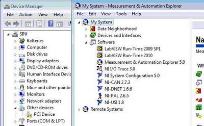
- PCI-8532 isn't available in MAX and Windows Device Manager indicates the card as "PCI Device" with an exclamation mark.
Here is a screenshot of Windows and MAX Device Manager:
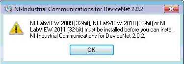
I can't install the NOR-Industrial communications for DeviceNet 2.0.2 on this computer because I get the following error:
Well, I have two questions
- How can I install and use the PCI-8532 and see with NOR-DNET 1.6.6? If this is not possible:
- How can I create an executable file on my system (portable) development with LabVIEW 2010 or 2011 LabVIEW and run this executable on the test set-up. I currently have on my development system:
- Professional 2010 LabVIEW and LabVIEW 2011
- NOR-DNET 1.6.6
- No hardware OR at all
- I have to install the NOR-Industrial Communications for DeviceNet 2.0.2 on my laptop (my development system)
- This will interfere with my current NOR-DNET 1.6.6 and then I select which driver to use at compile time
Thank you
Nick
Nick HY,
No, it is defenitely not a replacement yet and I will work with our Web Department who make clearer on our web page.
The development of the new API is pretty well done, but based on your feedback, we are planning to improve compatibility, so you can for example use the old APi 1.6.x and the new APi of 8532 on the same machine, so you can use the old and the new material on this same machine. Which would be important for you?
For the moment we intend not to allow only one type of material on the same machine to save you development time. Let me know what you think.
To clarify the situation today: The InCOM for Devicenet component is not part of LabVIEW. It's just a very simple means of communication with the I/o variables and blocks of function for the MS. The driver should install fine even without installed LV. The error message is quite a Bug on our side, and the solution would be to use the Builder installer LV to create a new installer that can install 2.0.x Incom Dnet driver without having installed Lv.
And today, you should be able to have the 1.6.x both pilot 2.0.x in parallel and use the API 1.6.x with old boards yonce and the variable approach of IO 2.0.x with your new Board of Directors.
I'll keep this post updated as soon as we have a stable Beta available I'll post something.
DirkW
Maybe you are looking for
-
Transfer Time Machine backup on the new disk, preparing already > 24 hours!
I followed the instructions on the web site (Time Machine: how to transfer backups from a current backup disk to a new backup drive - Apple Support -essentially a copy via the Finder) and after more than 24 hours the copy process is still "preparing
-
Satellite P10 804 upgrading wireless card
Hello Ive been trying to find a list of compatible wireless cards to upgrade my Satellite P10 804 but can't find. The wireless card is a Toshiba PA3171U-1MPC, but it does not have the standard 802.11 G and no WPA security. Anyone know of the good car
-
Portege R400-600 - the Infineon SW is old for MS Office 2007
The Infineon software that came with the laptop is old enough - and does not support the new office. Is it possible to get a free upgrade?
-
Re: Satellite L755 - Blu - ray player is not picked up after Win 8 upgrade
I have a Satellite L755-s1ep and I upgraded to Win8 and my blu - ray player does not work and I can't find drivers or a solution.
-
Windows vista will not let upgrade me to windows 7
had a new hard drive installed on my pc. recovered to the factory specifications and reinstalled PC windows7 home premium. had worse transtering the backup data. so I got the pc again, but this time it will not be upgraded because must be running V