two channels of analog output to 6259
I need two analog waves, my output 6259, I have generated the necessary signals but would help with seizure 2 signals simultaneously, how would I go about it?
The steps are quite the same, just that your 2D table consists of two different tables given 1 d.
Christian
Tags: NI Hardware
Similar Questions
-
acquire the voltage output of a channel of analog output current
I'm controlling a HV configuration rather sensitive analog output voltages. Is there an easy way to read the voltage level which is currently awarded by an analog output?
Hello
If you set your subVIs different voltages, you can be sure that the voltage you set in these screws are similar to tensions, you have to your output PIN. For example, you could write the value you give to the output in a variable and read this variable in you main VI.
Kind regards
Peter
-
How can I check if the counter entry is synchronized with the analog output?
Hello
I'm working on an application for counting photons. I use two channels of analog output on a PCI-6713 card to send a frame model to a set of XY scan mirrors. I then a photon count unit that emits a TTL signal when the photons are detected as a result of this raster analysis. I then use a surfboard USB-6211 to count the edges on this TTL signal.
I have problems that seem due to synchronization problems. I use the sample AO on the PCI-6713 card clock like the door of my meter on the map USB-6211. I use a trigger to start digital to analog output and a trigger of arms for the entrance to counter early. Is there a way to check that the analog output and counter entry of start of operations at the same time and are are synchronized? I basically want to monitor and compare the ao real sample of the PCI-6713 card clock door signal used by the jury of the USB-6211. I was able to export the sample AO clock and watch it on my oscilloscope, but not the signal from the door of the USB-6211.
Thanks for your help,
Brian
Update... It turns out that there is no problem of synchronization between my meter input and the analogue output. There was a difference of impedance when I connected my unit of counting photons to my USB-6211. This caused an error variable count rate. After accouting for this shift, the problem disappeared.
-
Control the analog output in *.vi
Hi you all,.
I have a PCI-6281 with a Bob SCB - 68 in any case, I use two channels of analog output to cross strains of certain instruments. Every time I restart the computer, I reset the tensions Explorer automization and measures. (I'm on measures and Explorer automization > devices and interfaces > NI PCI-6281 dev 1 > test panels... > analog output). Is there a way to have the VI set it each time I run it? THX
Watch the DAQmx Write.vi in the DAQmx palette. Also look in the viewfinder of the example (help-> find examples...) for the analog output DAQmx. There should be a lot of examples that you should be able to disassemble to simply adjust the tensions.
-
Read analog output channel value internally
According to this you can read the values of analog output of return without having to physically connect the wires.
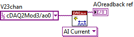
By using the technique described in the example given (DAQmx_Read_Output_Internal_Channels.vi) I'm reading a current area of OCCUPANCY on my compactDAQ cDAQ-9174 with a module of analog output current OR-9265.
The output channel is created in MAX and my vi can write values to him without problems
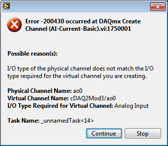
But when I try to create an analog input channel to read the output, an error occurs.
What I am doing wrong?
This is not supported by my hardware?
Or is the example given in the above incorrect link?
The example is 10 years old. Maybe, it does not work in LV2013.
Hi Jocker,
The link was not attached to your message, but I guess that's it: http://digital.ni.com/public.nsf/allkb/CB86B3B174763C3E86256FFD007A2511 as there the example of vi you mention.
The error you are getting is due to the use of the channel for analog output and trying to configure the task as a task of entry. You must use _aoX_vs_aognd as the channel of the task rather than on the output channel. This compares to the ground for the analog output values.
The NI 9265 is not on the list of the C Series modules that have internal channels:
So I guess that the module is not able to compare its output to ground. He would appear in the dropdown of the channel names if available.
Pete
Applications Engineer OR
-
Recommendations for hardware OR with a minimum 6-channel analog output
Hello world.
Currently I have the NOR-device, USB-6009. However, it offers only up to 2 analog output channels. I'll need to have at least 6 channels of analog output. Therefore, can anyone recommend me any device OR that matches my needs (preference is the USB series)?
Kind regards
Jonathan
Did you go to the page data acquisition . You can use the different selection tools to narrow down your choices. Given that you have provided only a single parameter (number of channels), it is difficult to recommend anything. Determine what else you need (sample rate, voltage range, etc.) and you can call your sales engineer OR local and get all the help you need.
-
measure with the two channels of the virtual bench simultaneously in labview, error 375903
Hi, I am trying two measurements simultaneously using two channels of analog input of the virtual bench. I chose the channel MSO 1 and 2 for the measures but I get error 375903 returned evewry time say the requested resource is reserved. I'm not under any other software which should use the virtual bench. The error occurs when I'm initializing the session, even before a measurement was made. Can someone tell me how to call each channel so that I don't get this conflict of resource reservation?
I have included the VI and a screenshot of the error.
Thank you!
NGKai wrote:
Hi, I am trying two measurements simultaneously using two channels of analog input of the virtual bench. I chose the channel MSO 1 and 2 for the measures but I get error 375903 returned evewry time say the requested resource is reserved. I'm not under any other software which should use the virtual bench. The error occurs when I'm initializing the session, even before a measurement was made. Can someone tell me how to call each channel so that I don't get this conflict of resource reservation?
ASM takes only supported a session unique instrument and your VI uses two. To use both channels, delete the second session MSO and specify channels in the MSO configure Analog Channel.vi
Here's an example that uses two channels brought:
VirtualBench: Bode Analyzer with the FGEN and MSO
-
Simulate the analog output of arbitrary waveforms
Simulate it Arbitrary Waveform VI Express can be used to generate analog signals to the physical channels in analog output mode systems such as the NI 9263? I am trying to use the VI arbitrary signal generator to produce a signal used to excite the magnetic coils.
Why don't you just try and see what happens? As far as I know, it should work.
-
I use the outgoing/incoming analog DDK with the DAQ 6341 SMU map.
The examples, for example aoex5, show a single timer (method outTimerHelper::loadUI), but the example shows the DMA loaded with same size of vector data.
There is a comment in the outTimerHelper:
 call rogramUpdateCount, which implies that memory sizes different pad per channel can be used.
(the comment is: switching between the sizes of the various buffers is not used)
Nobody knows what should be the format the DMA buffer for data from multiple channels with different frequencies?
For example, we want a0 with a sinusoid at 1 kHz and a1 with a sine wave of 1.5 Khz. What looks like the DMA buffer?
With the same frequency for each channel, the data are interleaved, for example (ao0 #0, ao1 #0; ao0 ao1 #1, #1,...), but when the frequencies for each channel is different, what the stamp looks like?
Hello Kenstern,
Data are always intertwined since each card has only a single timing for each subsystem engine.
To AO, you must specify the number of samples that will be released to the AO. You also specify the number of channels. Because he didn't is that a single engine timing for AO, each AO will be channel will be updated at the same time to update clock tick. Data will be interlaced exactly as shown in the example because each channel AO needs output at each tick of the clock to update. The data itself can change depending on the frequency you want to copy.
kenstern wrote:
For example, we want a0 with a sinusoid at 1 kHz and a1 with a sine wave of 1.5 Khz. What looks like the DMA buffer?
With the same frequency for each channel, the data are interleaved, for example (ao0 #0, ao1 #0; ao0 ao1 #1, #1,...), but when the frequencies for each channel is different, what the stamp looks like?
In your example, you must come with an update rate that works for the two waveforms (sine waves of 1 and 1.5 KHz). To get a good representation of a sine wave, you need to update more than 10 x faster than your fastest frequency... I would recommend x 100 if possible.
Update frequency: 150 KHz
Channels: 2
Then create you stamps that include complete cycles of each wave you want to produce based on the frequency of update. These buffers must also be of the same size.
Buffer 1: Contains data for the sine wave of 1 KHz, 300 points 2 cycles of sine wave
Buffer 2: Contains data for the sine wave of 1.5 KHz, 300 points, 3 cycles of sine wave
You can Interleave them as before. When the data are performed through the ADC, they are out different sine waves, even if the AO channels are updated at the same speed.
-
How to control the two analog outputs at a time
I'm new to LabVIEW and have some problems in DAQmx with control outputs analog multiple.
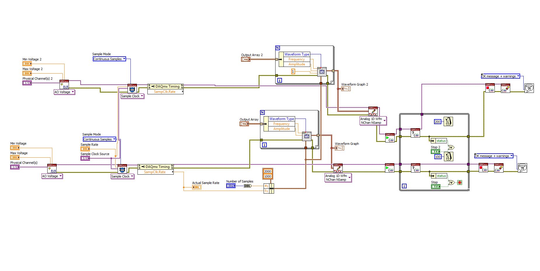
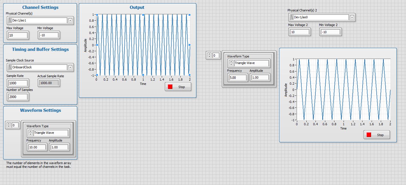
I want to set up a platform using BNC-2110 and PCIe6363 to control two rotating mirrors. The problem that I can only give an output (AO0 or AO1) at a time and I really have no idea how revise my LabVIEW diagram to control two outputs at the same time I met. I tried to change the outputs and it keeps a mirror turning instead of the old. Could someone help me with my problem and I would really appreciate. This is my blocked diagram and front.
Hi zrmaker,
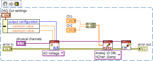
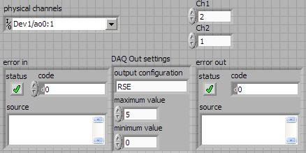
As mentioned by RavensFan, you should not create 2 analog outputs different tasks if you use AO0 AO1. To your façade > physical control or the channels > select the drop-down list of the control channel physical (s) > Browse > hold down the CTRL + select the AO0 and AO1 > Select OK. Once this is done, you will see that your control or the physical channels has the following input values: "Dev1 / ao0:1" which means that you will access to AO0 AO1.
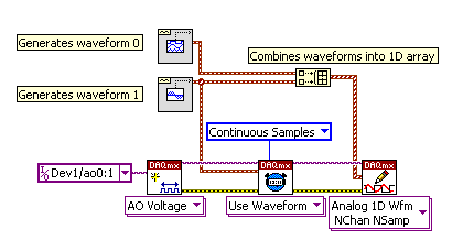
In regards to writing DAQmx, simply select Analog > multiple channels > samples multiple > 1 waveform (you should get the following: 1 d Analog Waveform NChan NSamp). Once done, you can just use table build to combine 2 different waveforms and plug in this table to DAQmx writing output. The first index will be the output for AO0 value and the other will be for AO1.
You can check this link on how to read or write from several channels: http://digital.ni.com/public.nsf/allkb/0C1ADEF06A54AB2D862575040066FD51
Additional reference:
http://www.NI.com/white-paper/2835/en/Hope that helps.
Warm greetings,
Lennard.C
-
Several simultaneous analog output channels
I use DAQmx-NOR-USB.
I want to simultaneously generate two analog output signals, i.e. change the two outputs at the same time.
Simple example:
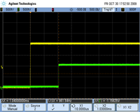
What is happening is that instead of two outputs simultaneous modification, there is 1mS delay:
I want to generate premium output, using two channels, but the delayed response is not acceptable.
Any suggestions?
Hi Seth B,.
Yes, it works!
A note: to make visible this property, I had to turn on "display all the attributes" in the menu "Select filter" (right click on the node property).
Thank you.
-
Error-200524 when you try two analog output voltage signals
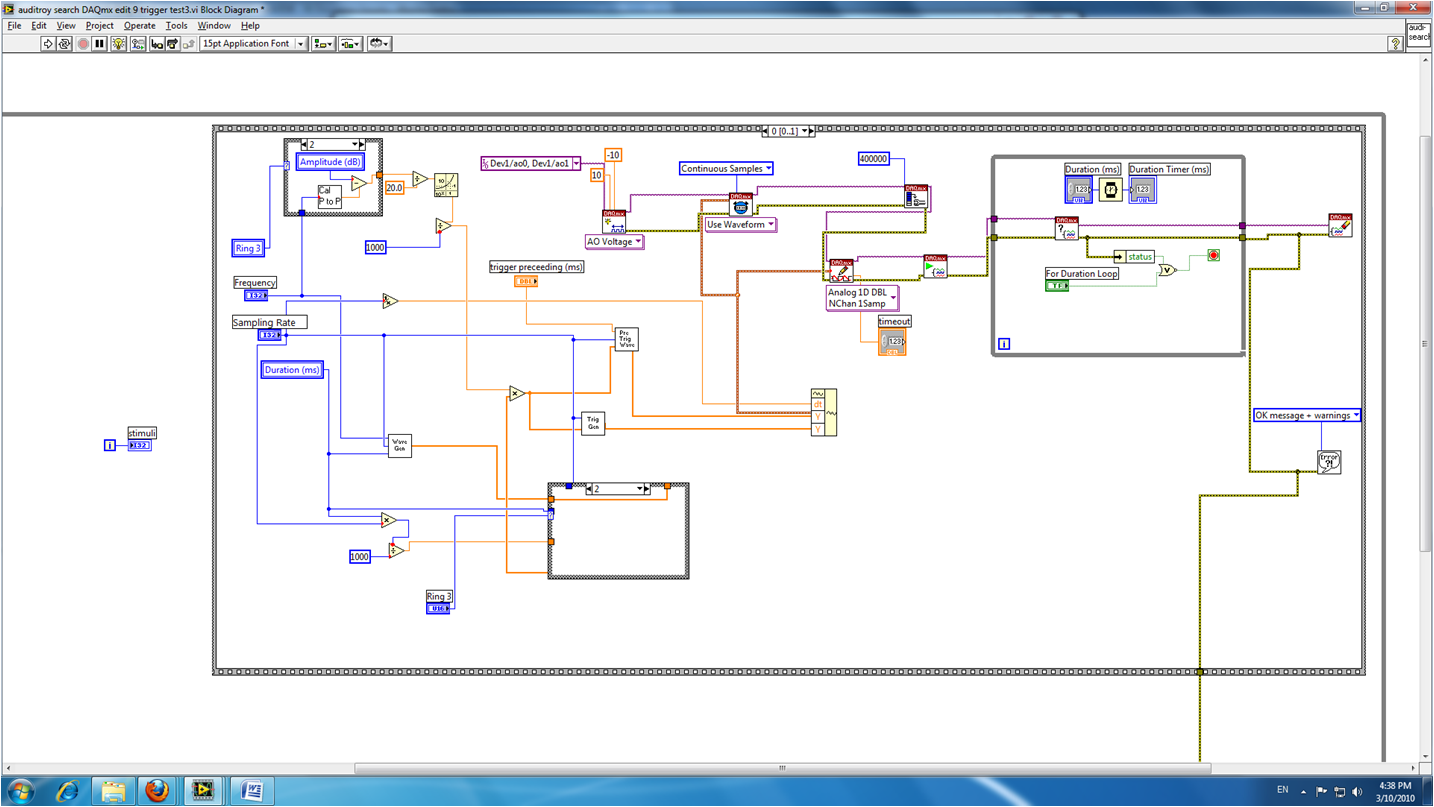
I am train to the output of two signals to analog voltage simultaneously using Labview 8.2.1. One is a waveform to produce sound, and the other is a trigger on another computer (using labview 6.1). I've been doing error-200524 write DAQmx. Here is a screenshot of my VI:
The error message says:
"Measurements: writing cannot be performed because the number of data channels does not match number of channels in the task."
When writing, provide data for all channels in the task. You can also change the task so that it contains the same number of channels as the written data. "How can I solve this problem? Thank you.
Show you only a waveform in the block diagram.
Here is a picture that shows what I told you to in my previous post.
The waveform connected at element 0 of the 'picture to build' will be emitted on channel 0. The waveform that is connected to the item 1 of the 'picture to build' will be emitted on channel 1. The instance of 'DAQmx writing' is 'Analog 1 D Wfm NChan NSamp.
Hope that is more clear!
d
-
variable phase shift between two analog output signals
Hey! I would drive two different piezo elements with an sine - / square signals and have a phase shifted output signals. After some trail and error, I was able to get a second analog output on my card PCI-6221 (using LabView 8.2) also allowed me to have different amplitudes for both signals. However, I could not output signal having a frequency different and most importantly to my request to have one of the signals variably shifted phase.
Thanks for the very useful suggestion. I have attached the file .vi installation I've run so far.
Hello!
A way to generate waveforms is using the analog waveform Toolbox. I created an example VI that is attached and that shows you a way to use the base generating function VI. I saved for LabVIEW 8.2.
I hope this helps!
-
How to change the gain of an analog output
I want to have a resolution of at least 500 v microphone. I thought that you could do this in two ways: one, to determine the maximum and minimum values, and two, to change the gain of the channel. I use a PCI MIO 16th 4, also known as the name of PCI 6040E and a CBS 68.
The NO 6040E manual family I read than analog output bit resolution is 12 bits. Usually a range of 0 - 10V or - 5V - + 5V, which gives about 2.44mV resolution. I thought that by changing the minimum and maximum output values I could therefore change the range and therefore to change the resolution. I want at least a 500microV (0.0005V) resolution. By changing the range 0 - 1V, I should get around 244.14 microV resolution.
The thing is that when I run my simple program, it displays the voltage I want, but it only increments around every 5 iterations of said 500microV, which is around the default resolution of 2.44mV, which indicates that the resolution has not changed (I use an osciloscope to measure physical strength).
My other option to change the gain should how to proceed, if possible. But I don't know where and how change that, and he does not appear in the DAQmx channel properties. Any ideas on how to do this, or perhaps another solution to my problem?
P.S. That's a linear ramp drive a piezo and take pictures while doing so, just in case you were wondering why I wanted to solve this problem.
Thank you for any help in advance!
You have not read the card correctly. The analog output is a range of 0-10 or + /-10.
-
Analog output of signal generation custom
Hello
I have a VI that generates a signal from the values in an excel worksheet. I'm trying this waveform through an acquisition of output data. I use a box NI USB-6211.
I copied the exit code for the acquisition of data from other VI that generates a sinusoidal signal coming from an excel worksheet. This program works very well. (attached for reference - Analog Output VI + sinusoidal waveform)
I have two problems at the moment. First of all, I get error-200560 about waiting until the function, attached.
Second output amounts only to about 5.5 v instead of 9V specified in the data.
My VI generate several types of waveform according to selected tests, but I'm trying to get an output DAQ working with the first test, named "disconnection of the battery" work first before implementing it in the other tests so please ignore others for now. To run this battery select VI disconnect under tests select then direct to the attached excel (BD values under 10V) file.
I hope that I myself have pretty much explained, otherwise please ask for more! I'm new to LabVIEW so your help would be very appreciated.
Thank you very much
Parker
aeParker wrote:
I've made a few improvements to the VI but I always feel the DAQ 5 Cap output, 5V.
Dear Parker,
I guess that this statement is based on the values in the chart show, AO 0. However, this is not (necessarily) the voltage produced by AO 0, but rather the tension being sampled by AI0. If you look at the DAQmx create channel for the AI voltage channel, you will see that you have left entries Maximum and Minimum Value unwired, which means that they take their values default to + 5v and - 5v. This may explain the behavior of cutting that you observe. Try the + 10 and -10 wiring and see if that solves this problem.
Bob Schor
Maybe you are looking for
-
Why a new MacBook have a load cycle count of 18
I just bought a brand new MacBook(early 2016) last week and immediately noticed that the number of cycle load was 18 years old. Is this normal or have I been given a return or a refurb? Thank you!
-
I just bought a used A1283. I took it to Best Buy to see if they could make me the administrator. They said that having seen lines vertically on 'their' screen and on mine as well. I never noticed at home only matter of freezing. They said that t
-
I have the disk microsoft works 9, can u tell me what is it for
I need to know what this disc
-
Said file is empty, but I copied the search inside.
Original title: FOLDER EMPTY DOUBT . Dr. Vikram here. I want to know that how can I solve this problem. I have partitioned my disk c D and E drives. My tam srol e reader shows that this disc contains files and folders, but when I click above and go t
-
Some time before the Board of Directors works not in a pleasant way... The user experience was very bad, something happened... I think it's good, running now... Moderators or administrators of this forum, the arrived, the answer is that the problem b