USB6008 line multiple outputs with DAQmx
Hello
I am trying to connect and control only the direction of a DC 12V the gearmotor using a critical bridge in H Velocty microcontroller requiring a digital input of 3 lines of our NI USB 6008. I was able to use the wizard DAQ to power the motor using 3 functions assistant separated for the 1 task controlling the output of high/low of each line separately, but for this, I have manually to each line output. i.e. 3 Boolean switches should be selected the correct way to move the motor one way or the other.
What I want to do is to use a control Boolean to train the engine turns clockwise or counterclockwise, but can't convert the Boolean control in the form of data that requires the DAQ Assistant. I have to take my entrance and then build the table of 1 x 3 necessary to drive the engine? But then how I let the DAQ know I want that each value in the array to control a different line digital acquisition of data output?
Thank you very much for your help!
Hi Leanne,
Try this. If you have any questions, give a complaint. Also, please look at the examples DAQmx LabVIEW... under 'Help', click on 'Find examples'.
Diane
Tags: NI Software
Similar Questions
-
Synchronization of the inputs and outputs with different sampling frequencies
I'm relatively new to LabView. I have a NOR-myDAQ, and I am trying to accomplish the following:
Square wave output 10 kHz, duty cycle 50%.
Input sampling frequency of 200 kHz, synchronized with the output that I get 20 analog input samples by square wave, and I know what samples align with the high and low output of my square wave.
So far, I used a counter to create the square wave of 10 kHz, display on a digital output line. I tried to pull the document according to (http://www.ni.com/white-paper/4322/en), but I'm not sure how sample at a different rate than my clock pulse. It seems that this example is intended rather to taste one entry by analog clock pulse. There may be a way to create a faster clock (200 kHz) in the software and use that to synchronize the analog input collection as well as a slower 10 kHz output generation square wave?
I eventually have to use the analog inputs to obtain data and an analog output to write the data channel, so I need the impetus of the square wave at the exit on a digital PIN.
How could anyone do this in LabView?
Hi Eric,.
All subsystems (, AO, CTR) derive from the STC3 clocks so they don't drift, but in order to align your sample clock HAVE with pulse train that you generate on the counter, you'll want to trigger a task out of the other. I would like to start by a few examples taken from the example Finder > Input and Output material > DAQmx. You can trigger GOT off the train of impulses, start by Gen digital Pulse Train-keep -you probably already use a VI like this to generate 10 k pulse train. AI, start with an example like Acq Cont & chart voltage-Ext Clk - Dig Start.vi-you'll want to use the internal clock so just remove the control of the "Source of the clock" and it uses the internal clock. From there, simply set the "Source of the command" either be the PFI line generates the meter, or ' /
/Ctr0InternalOutput '-assuming that you are using the counter 0. You'll want to make sure that the start of the task HAVE faced the task of counter I is ready to trigger off the first impulse. They should be aligned at this point. For debugging, you can use DAQmx export Signal to export the sample clock - you can then brought the train line and the PFI pulse to make sure that they are aligned.
Hope this helps,
Andrew S
-
Save multiple pictures with a dialogue box
Hello
I try to add a feature to a program of mine to record multiple images with a single click, but I get these ridiculous errors saying "file not found" to "Open/create/replace the file" function, which is set to create. Of course, the file is not found, I'm trying to create it!
Can someone look at my code and tell me what is the problem? Thank you!
Hey manufacturer.
I took a glance at your VI and it seems to me that the problem is in the Express VI to file dialog box, you choose a location to save the files, but this situation is never created. So if I want to save my images in TestFolder, it seems that your intended functionality is for images to be stored in a subfolder called 'Images' (or whatever the user enters a name in the file dialog box) so that the final result are images being recorded TestFolder/Images.
If this is the case, you can simply add a node function to create a folder in your block diagram (look in the programming > e/s from file > Adv IO file for this). You can wire directly from the output of selected path in the dialog box file to the path of the node Create Folder entry. I recommend you to place this node in line with your existing code in order to ensure that the creation of files ends before you try to save files in this location.
If, instead, you want the user to select an existing folder and save images directly into that, simply have the click of the user the "Current folder" button in the dialog box of the file, rather than enter a new name and click Save.
I hope that helps and let us know if you have any other questions.
-
Apple Dock of lightning - line level output?
I have a question that maybe with that you audiophiles out there can help. Descriptions and comments from the dock connector 30 pins for the pre at first touch screen iPod claimed (correctly I think) that the mini stereo 3.5 mm output port of these docks early provided output audio line level, offering the best quality audio when connecting to the RCA inputs of the channel to audio amplifiers domestic. I am trying to determine if the pier lightning currently available for iPods and iPhones to end model offers the same line-level output signal from its 3.5 mm plug. I'm having a hard time getting a definitive answer. My research here on the web and the responses from Apple store geniuses have contradictory opinions. Specifically, I want to be able to use the lightning dock to connect a 5th Gen iPod or iPhone 6 to my stereo. Thank you
It is line level, not affected by the volume of the phone controls.
-
I use the outgoing/incoming analog DDK with the DAQ 6341 SMU map.
The examples, for example aoex5, show a single timer (method outTimerHelper::loadUI), but the example shows the DMA loaded with same size of vector data.
There is a comment in the outTimerHelper:
 call rogramUpdateCount, which implies that memory sizes different pad per channel can be used.
(the comment is: switching between the sizes of the various buffers is not used)
Nobody knows what should be the format the DMA buffer for data from multiple channels with different frequencies?
For example, we want a0 with a sinusoid at 1 kHz and a1 with a sine wave of 1.5 Khz. What looks like the DMA buffer?
With the same frequency for each channel, the data are interleaved, for example (ao0 #0, ao1 #0; ao0 ao1 #1, #1,...), but when the frequencies for each channel is different, what the stamp looks like?
Hello Kenstern,
Data are always intertwined since each card has only a single timing for each subsystem engine.
To AO, you must specify the number of samples that will be released to the AO. You also specify the number of channels. Because he didn't is that a single engine timing for AO, each AO will be channel will be updated at the same time to update clock tick. Data will be interlaced exactly as shown in the example because each channel AO needs output at each tick of the clock to update. The data itself can change depending on the frequency you want to copy.
kenstern wrote:
For example, we want a0 with a sinusoid at 1 kHz and a1 with a sine wave of 1.5 Khz. What looks like the DMA buffer?
With the same frequency for each channel, the data are interleaved, for example (ao0 #0, ao1 #0; ao0 ao1 #1, #1,...), but when the frequencies for each channel is different, what the stamp looks like?
In your example, you must come with an update rate that works for the two waveforms (sine waves of 1 and 1.5 KHz). To get a good representation of a sine wave, you need to update more than 10 x faster than your fastest frequency... I would recommend x 100 if possible.
Update frequency: 150 KHz
Channels: 2
Then create you stamps that include complete cycles of each wave you want to produce based on the frequency of update. These buffers must also be of the same size.
Buffer 1: Contains data for the sine wave of 1 KHz, 300 points 2 cycles of sine wave
Buffer 2: Contains data for the sine wave of 1.5 KHz, 300 points, 3 cycles of sine wave
You can Interleave them as before. When the data are performed through the ADC, they are out different sine waves, even if the AO channels are updated at the same speed.
-
Analog output with counter Falling Edge
Hi all
Here's the iamge which describes what wishes to accomplish. I would like to trigger that the AO output with the edge of the fall of the meter.
I have set the clock for my AO as the counter.
The analogue output should be raised whenever the Digital signal meter falls
SAMPLE_SIZE = 80
SAMPLING_RATE = 40 #Samples are written every 25 milliseconds
TIME = float ((SAMPLE_SIZE) / (SAMPLING_RATE))CREATE TASKS
CREATE CHANNELS OF AO
CONFIGURE THE TIMING CHANNELS
DAQmxCfgSampClkTiming (taskHandleAO, "PFI12", SAMPLING_RATE, DAQmx_Val_Falling, DAQmx_Val_FiniteSamps, SAMPLE_SIZE)CREATE TASKS
CREATE A CHAIN COUNTER
# Time high-low + time equals 25 milliseconds and is proportional to the frequency of sampling
DAQmxCreateCOPulseChanTime(taskHandleD,"DAQ/ctr0","",DAQmx_Val_Seconds,DAQmx_Val_Low,0.00,0.005,0.020)# The values of voltage DAQmx writing
DAQmxWriteAnalogF64(taskHandleAO,SAMPLE_SIZE,0,10.0,DAQmx_Val_GroupByChannel,Voltage,None,None)# DAQmx AO task start
DAQmxStartTask (taskHandleAO)# Counter DAQmx Start task
DAQmxStartTask (taskHandleD)#TIME is equal to the total time for the writing samples
DAQmxWaitUntilTaskDone (taskHandleD, 2 * TIMES)I get an error every time that I run the task:
DAQError: Over Acquisition or generation has been stopped until the required number of samples were acquired or generated.

 function DAQmxStopTask
That's because my AO task is stopped for some reason any.
Is there an obvious problem with the code. Can it be structured differently?
best regards,
Ravi
I do all my programming in LabVIEW, so I'm pretty limited to help with programming syntax text. That being said, here's what I * think * I see:
Your AO task issues a call to DAQmxCfgSampClkTiming, but is not your task of counter. This probably leaves you with a meter spot which creates only a single impulse, which causes only a single AO D/A conversion. In LabVIEW when I need a pulse train, I would call a similar function of the synchronization with the clock mode is defined as 'implied '.
Hope this helps you get started, I don't know enough to give you the specific syntax in the text.
-Kevin P
-
With a sampling of the data with DAQMX, error-200279 occurs when making 2d array dbl
Hello
I did a system of simple analog voltage with DAQMX data acquisition.
It is made for reading of capacitance, where output capacitance value out of a circuit in the periodic voltage signal.
What I want is to get data from four capacitors simultaneously through four channels, using samples n n (dbl 2d).
The structure of my VI is almost similar with examples of continuous sampling of voltage in LabView, with the exception of a few other calculations in the loop.
And for the synchronization of the trigger, I've corrected the edge of release with the external signal from the capacitance reading circuit.
Version no. 1 has a channel for data input voltage. Version n ° 2 has four channels for the input data.
While ver.1 can get accurate reading of four capacitors circuit data each (a single channel at a time),.
ver.2 acquires four channels of data, with a single thin data channel, all the others were wrong.
I saw a 200279 error occur in the DAQMX read part 2d dbl, so I tried increasing the buffers by changing the sampling frequency or the number of samples, but it wasn't everything.
I rose for most of the forums with the 200279 error, but the solution would not work on mine.
Anyone can find the problem? I will attach my screws it may include a bit of Korean language, but most of them are in English, shouldn't be too hard to recognize. Sorry for the inconvenience.
Oh I forgot, my DAQ is NI USB-6259, and it works in Win XP sp3 and LabView 8.6.
Thank you.
Hello Azurenight,
The 6259 is a DAQ card of the M Series Multiplexed, which means that it is not possible to sample each signal at the same instant, rather the channels are all sent through the ADC even and must be sampled in order. More information on this can be found here:
LabVIEW Help: Multiplexing compared with simultaneous sampling
http://zone.NI.com/reference/en-XX/help/370466W-01/mxcncpts/multisimulsamp/
It may still be possible to get the data you need with the card you have - could you give more information about the maximum eligible period between samples on different channels?
If you require * real * simultaneous sampling, you will probably need different hardware.
Kind regards
-
SCXI-1160 with 'DAQmx switches Open Relays.vi' list of syntax of relay.
Hello
I re - write a request for a RT PXI controller that handles of many SCXI-1160 relay cards. We want to abandon traditional DAQ to DAQmx. I don't have the controller with me and I would like to know the syntax to use in the list of relays for the 'DAQmx switches Open Relays.vi". I want to use this VI as a command "several relays. I did a lot of research without success.
I need the syntax that take into account several chassis, several cards, relay and individual relay range.
Any help?
Thanks in advance.
Michel
Hello Michel,
Sorry for this confusion.
You can find some general examples for switches of programming under help > find examples in LabVIEW. I would go to the output material & > DAQmx > switches and check out some examples below to see if any programs already exist for your goals.
As for your specific question, at the beginning of each program, you must DAQmx switch topology Set and Reset. This allows the users to define the topology of the switch for each individual switch card in a chassis. A good community it shows a simple, you will find a complete example of using these two screws, we discussed here.
Finally, the SCXI-1160 is an electromechanical lock change, so in the case of a power outtage, the switch will retain its State. However, switching on, all default relay to their States normally connected.
Thank you!
Lisa
-
Hello
I am currently working on a Senior design project where I have to measure rpm, torque, pressure and temperature. I use strain gauges, pressure sensor and a Hall effect sensor, thermocouples for these readings. A myDAQ collects readings rpm and pressure while a cDAQ collects couple and readings of the temperature with NI 9211 and NI 9237 modules. I have created LabVIEW screws for each sensor and they work. The problem I have is when I try to create a VI with DAQmx who reads all the values of these sensors simultaneously. The VI I joined randomly displays one of the measures while other measures remain empty. How can I change my VI so I can show all my readings at the same time?
Yes. Create multiple tasks, where all the strings that are common to a specific device are grouped in the same task. Then go and run these tasks in parallel. Do you need a precise synchronization between the tracks in the different devices? If this isn't the case, then the method should work perfectly. If you need a precise timing, things would get more complicated, but might not be impossible.
-
Repeat the Scans with DAQmx read/write
Hello:
I use DAQmx vi to generate signals on channels ao0/1 a reading of the signals of the channels ai0/1 a card NI USB DAQ of 6251. I do this by using the read and write of vi and a trigger vi. This vi will run successfully for a single analysis. Now, I need to be able to perform multiple scans with the same settings but separated by 5 seconds or more. When I click on Scan, the vi analysis. However, when I click scan again once it does nothing and I don't know how to scan again.
The vi VU RAMP MOD (not included) is simply used to generate the shape of the signal.
Thank you!
-
How to set up multiple monitors with desktop
How can I set up multiple monitors with desktop computer? (DVI output)
http://Gizmodo.com/5141386/win-7-tip-adding-extra-monitors-is-so-easy-a-Caveman-could-do-it
-
Multiple selection with binding variable error
Hello world
I tried to put in place an array of adf multiple selection with another table, by following the tutorial (http://www.oracle.com/technetwork/developer-tools/adf/learnmore/75-multi-parent-row-detail-views-328078.pdf), page 3.
I created all things and first of all I had an exception error, which I fixed, but now, whenever I try to select multiple lines, it won't update the table of the adf.
In this example, I choose a service line and it shows the emplooyes, but every time I try to choose another line by ctrl clicking on it, the employees table be updated.
Since I tryied to follow the tutorial, I'll put the code for the bean, I created for this purpose (it's a little different than the code given by the tutorial, but only because I had to get rid of the exception error)
I use jdeveloper Studio Edition Version 12.1.2.0.0.
Here is my code for the bean.java:
Select listen port defined for the departments table. The selected line keys are read in the reference table.
For each line, the Department ID value is read and added to a string buffer that generates a comma-delimited
List of the departmentIds. In the end, this string is passed as an argument to the link of action ExecuteWithParams
{} public void onDepartmentTableSelect (SelectionEvent selectionEvent)
variable to hold the string containing the selected set value line departmentId
StringBuffer departmentIds = new StringBuffer();
Go to the main table to read selected line keys
RicheTableau rt = selectionEvent.getSource ((richeTableau));
RKS RowKeySet = rt.getSelectedRowKeys ();
Iterator selectedRowsIterator = rks.iterator ();
memorize the current line to place it back in the end key
CurrentRowKey () rt.getRowKey = (list);
for each selected master line, determine the departmentId
int size = 0;
{while (selectedRowsIterator.hasNext ())}
size ++;
The rowKey () selectedRowsIterator.next = (list);
each value is terminated by a comma
If (departmentIds.length () > 0) {}
departmentIds.append(",");
}
take the current line
rt.setRowKey (rowKey);
JUCtrlHierNodeBinding wrappedRow = rt.getRowData ((JUCtrlHierNodeBinding));
Line rw = wrappedRow.getRow ();
/*
Number departmentId = (number) rw.getAttribute ("DepartmentId");
*/
int departmentIdInt = rw.getAttribute ("DepartmentId") (Integer);
oracle.jbo.domain.Number departmentId = new oracle.jbo.domain.Number (departmentIdInt);
departmentIds.append (departmentId.stringValue ());
}
back the foreign currency on the line
rt.setRowKey (currentRowKey);
Run the query on the detail table
BindingContext bctx = BindingContext.getCurrent ();
BindingContainer links = bctx.getCurrentBindingsEntry ();
OperationBinding executeWithParams = bindings.getOperationBinding("ExecuteWithParams");
executeWithParams.getParamsMap () .put ("departmentIds", departmentIds.toString ());
executeWithParams.execute ();
refresh the detail table
AdfFacesContext adfFacesContext = AdfFacesContext.getCurrentInstance ();
adfFacesContext.addPartialTarget (employeeTable);
}
}
If someone has an idea of why it isn't updated table, please answer. Any idea can help.
Thanks in advance.
Greetings,
Frederico Barracha.
Finally, I found the problem...
The problem was that I had to remove a line in the properties of my table, the property services: selectedrowkeys, because he only spent the last selected row.
Yet, I apreciate the help and I had to replace a code in the bean.java, in reason of the exception error and you had to do. Maybe I did a configuration in the wrong way and he would not.
Thanks for the help.
Kind regards
Frederico.
-
Connection to a TV with HDMI output with a Dual-Link DVI adapter
I have two monitors connected to my MacPro late 2013, an HDMI port and the other on the Minidisplay port (with a Mini DisplayPort to DVI adapter). Then I have a third monitor used for dubbing tracks, (22 in.) connected to an another mini display port with a Mini DisplayPort to Dual-Link DVI. Now, I don't want to connect to the Dual-Link DVI adapter a led TV 40 "in replacement of the monitor 22 '', so that I can make the tracks of dubbing in a better way. But the led TV has a HDMI port. The question is: can I connect the TV led to the Dual-Link DVI adapter, simply using an adapter DVI to HDMI? It work?
Not used that exact configuration but should work.
See here to ensure that you do not overload a single BUS:
Use multiple screens with your Mac Pro (end 2013) - Apple Support
Al
-
Multiple accounts with the same email
I have an account I can not connect to after my daughter it has disconnected. I tried to reset the password, but I get an email on my account to other girls: S (same email)
I guess I have 3 accounts with the same email, but only the latter can created recover!
Not even my main Skype has a chance
I'm not 100% sure but it is most likely that I used the same email to whoever I have to reset - what can I do?
In fact, this morning I managed to log on to the account of an iPad without frills but the pc refuses to sign ^ ^ ^? "Skype cannot connect" - what is happening?
I also discovered that I could connect via a browser, but not via the Skype program... So I uninstalled and installed again and it's working now...
I've now changed the email so I have 3 accounts with the same email address as Skype seems not to be able to manage multiple accounts with the same email! -
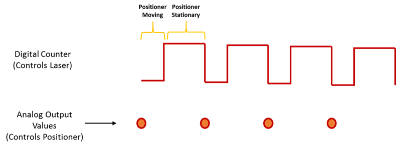
Synchronization of analog and digital output with the external sample clock
Hello
First of all sorry for my English, I will try to explain what I want to do.
I want my PCIe-6321 to send two custom signals (modification sawtooths) on a mirror controller. I would also like to generate output with my card at the beginning of each tooth of saw. Everything must be synchronized with an external k-clock signal of 100 kHz. The idea is that whenever the PCI receives a trigger to external clock, it sends two analog output voltages and when he received 1024 clock ticks it will also send a pic of triggering TTL. What I do is first prepare the map and after that in a loop sending and modifing the output values of the two signals and at the same time send a digital signal Boolean in each arch, so when's done it 1024 iterations of the loop I send an event to the digital port. Attached you can see.
The problem is that I don't know how to synchronize both. Can I use the sample clock just to the analog output? I can use sample for the two outputs clock, or do I need to use the output of the meter? If don't know how to use it here.
If I do nothing else bad/wrong, I would be grateful for feedback.
Thanks in advance,
PabloI don't know how but I find the solution. I'm generating more than a positive value (as I was triggered maybe very fast the oscilloscope has been absent there). If I put the sample clock of digital output to use the sampling/ao/Dev1 clock that it doesn't, but if I put to use the same source as the OD (terminal where my external clock is connected), but the trigger to start the DO to be Dev1/ao/StartTrigger this works. I don't really know why, but it does.
Thank you for your patience and your help. I put here the final code.
Maybe you are looking for
-
iCloud showing my name with my son ID
Hello I just got my wires to connect to his iPad using his email ID of iTunes. When it connects it happens with MY name at the top & his email to iTunes under. Why this is happening and how I can change it's his name on his iPad? Thank you for all su
-
Even thought is selected the option ' when Firefox starts to show my windows and tabs from last time "I always have the default page of Firefox.
-
How can I connect my DVD player to my new Imac with a bolt of lightning for a HDMI cable
I use the latest version of the software of El Capitan. I tried several times to use the Imac as a screen to watch my DVD without success. Can you advise what I'm doing wrong?
-
Smart search in Safari does not
My smart search to safari doesn't seem to work for the moment. It will not list the sites visited or even go to them when I enter in the search field and seems to jam as well. I erased from history, empty Web site data and even checked for extensions
-
Media Player won't play content protected after the restoration of PC
Media Player support? Media usage rights acquisition. I can't plays music, that I bought in the past. I also don't remember the user name and password with the fact that he said that I signed. In fact, I don't remember signing up! I have a password /