Using DAQ Assistant to read voltage of 9205
I am new Nock in it and I tried to read the voltage level of 9205 relating to 9172. I use it in XP mode virtual because windows 7 does not have labview 8,9. I installed the drivers for data acquisition.
When I check the meter in automation and Explorer, it works very well which means it reads im DC voltage supply. When I created a VI facilitate data acquisition, I chose the right channel, the entry as analog voltage, the numeirc indicator shows it is-10 to 10. I noticed he did the same thing, even once the USB is disconnected, which means that the function helps daq was not save the data of the 9205.
Can someone help me?
Hi aaclabview,
The way in which you have added the device to MAX makes the device act as a simulated instrument. Simulated instruments only generate sine wave data to test a piece of code without using any material. A simulated device has the icon yellow as shown in the screenshot you provided and are completely dissociated from any material, so add or remove the usb device has no effect.
The problem with the help of Windows XP mode as mentioned in the above KB is the USB transfer must be enabled for the measurement and Automation Explorer inside the Virtual Machine detect the device. Using the unit in this way is not supported or recommended by National Instruments and can lead to instability and the latency of the errors in the acquisition of data even if a connection is established.
It is a more sure bet to try and install LabVIEW and hardware drivers DAQ as described above on the real Windows 7 machine to try and run inside the XP mode.
Tags: NI Software
Similar Questions
-
Using DAQ Assistant with a system remotely
I'm new to LabVIEW and National Instruments hardware and I am trying to use an instrument with LabVIEW using the DAQ Assistant. I use a PC with Windows Vista and I am connected via a network to a PXI-8108 controller in a PXI-1050 chasiss chassis. The instrument is just a thermocouple which I use to become familiar with everything. The thermocouple is connected and the connection SCB-68 block which is connected to a PXI-6221 multifunction data acquisition in the chassis. I am able to create a task in MAX under remote system and everything seems to work. What I want to do is to use this instrument in LabVIEW, and it seems that for this I need to use the DAQ Assistant, but when I do it says no supported device is found. I wonder if there is a way to get LabVIEW lean on the remote system to see the acquisition of data and the thermocouple.
All advice is appreciated.
Thank you
Hi all
Ben is correct. RDA is no longer supported in DAQmx. We have another way to use DAQmx with a remote system. It is use DAQmx with an OPC server or simply by shared network variables. There is a section of the base of knowledge here that should help you get started. You should also take a look at the developer section area here. The basic idea is that you can use a variable shared within labVIEW that is bound to a variable shared on your networked machine. In this way, you can write and read values from a task DAQmx. Look at the instructions in the above two items and let me know if you have any questions.
Kind regards
Paul C.
-
Control relay with Boolean switch using DAQ assistant 9481 - problems
Sorry for what may be a stupid question but I'm stuck in quicksand.
I use a relay module 9481 and have two external relays connected lines 0 and 1.
When I create a digital output 0 line by line, I can run the test inside the express and activate the relay and turn off without problem.
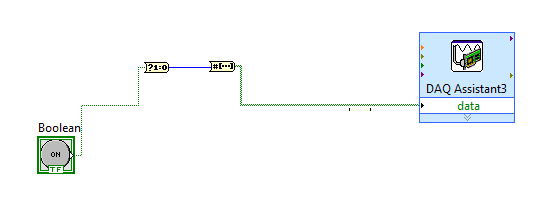
The generated block DAQ expressed expects a Boolean input of 1 d. (See attached photo).
I want to connect a Boolean switch relay line disk 0. You can connect live not because the switch is Boolean and the input is Boolean 1 d - I'm a conversation in the pict.
All plumbing lines display results, the relay never active.
Any bunch would be greatly appreciated! Thank you
Mr._Mechanical,
Welcome to the Forums of switch OR this forum is generally intended for products OR-SWITCH [such as the NI PXI-25xx & NI SCXI-11xx], I think I know the answer to your question.
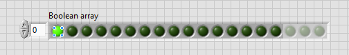
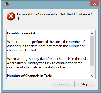
I think the reason why it's a failure is the conversion you make generates a table of 16 Boolean [as the 'boolean to (0,1)' function creates a data I16 type] with your data more false data points 15.
When you try to control the relay, he sees 16 datapoints are you Commander to a single port [channel] and so error out.
My suggestion would be to use normal DAQmx digital output screw [with, he set up as ' Digital > single channel > single sample > Boolean (1 line) "] rather than the DAQ assistant.
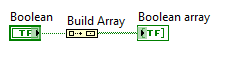
If you use the daq assistant, simply by using the function 'Building the table' will transform your simple Boolean data point in a Boolean array containing a single element.
While the DAQ assistant is very easy to use, I recommend that you use the DAQ assistant, because this reduces the features and increases the execution time.
-
Outbreak of DAQmx N-sample and the Acquisition using DAQ Assistant
Hello!
I'm still fairly new to LabVIEW and I am working on all the points of connection. I would like to acquire a finite number of samples of analog data from a CompactDAQ system when a Boolean event of internal software (like a button of VI). I followed the examples to implement the acquisition with the DAQ Assistant, which works very well. I don't understand how I can use a software trigger, but I don't see how hardware triggers are configured in the trigger tab in the DAQ Assistant.
I don't know that this should be very simple; Maybe I'm just ignorant of the configuration used for this sort of thing. Also, I could find soon I need to go beyond the DAQ Assistant for some of what I want to do, so any pointers to good references or tutorials on programming DAQmx are welcome.
Thank you!
Ryan
You can simply put the acquisition within a value of the Boolean control change event.
-
Disadvantages of using DAQ Assistant
I need 2 analog inputs continuously at 5-10 kHz from the sample and then use a combination of producer consumer and State Machine for the processing of data in real-time.
In most parts of the example I've seen, people always use Subvi of data acquisition groups. Even though I know how to set up getting data using the Subvi, I like to use Express VI DAQ Assistant to perform data acquisition.
Known disadvantages of the use of VI express in my case (see 1st line)?
With the help of an express VI will slow down time of execution and, therefore, your time of iteration of loop due to the fresh general partner. If you are concerned about the timing of your program, then you should strongly consider using the DAQmx API screws.
-
PID control using DAQ assistant
Hi, I'm generating sine wave using acquirng and function generator cela DAQassitant in my computer using USB6211 DAQ and labview. I want to manipulate this singal granted using the labview PID command and use the result of PID to generate an analogue of singal feedback (similar to that of entry). But when I run the code, it gives me an error that the buffer size is less. How can I increase the buffer size so that I can generate the singal output continuously. I have attached the file .vi
Thanks a ton.
Krishna
Hello Krishna,
get rid of the DAQAssistents and use the plain DAQmx features!
It is never a good idea to use the son of DDT in combination with points of constraint: what kind of data does it not provide your DAQAssistent and expect your PID?
-
DAQ Assistant: Reading of the samples that are no longer available
I'm trying to use the DAQ Assistant to read some data, but I get "error 200279 occurred at DAQmc Read (analog 1-d Wfm NChan NSamp) .vi:2.» The error message suggests to increase the size of the buffer, most frequently read data or by specifying a fixed number of samples to read instead of reading all the available samples. My sync settings are as follows: continuous samples for the Mode of Acquisition, 1 K samples to read, 1 K Sample Rate (Hz). I'm curious to know what would be the best settings for this. If I set the mode to 1 sample (on request), would simply take a sample each time the loop works? Help, please.
Thank you
Brian
Brian,
Please post on the Forums of NOR. Adnan a reason on why you get this error. If you use the sample on request, you will get only a value returned for each iteration of the loop. If you only need to try from time to time and there is no need to be very consistent, then this might work for your applications, but it depends on what type of application you have. How fast do you need taste?
-
Using the DAQ Assistant. can I create a VI that measures continuously during a fixed time?
I use LabView to an NI USB-6009 enclosure, with two accelerometers like my analog input. When you use DAQ Assistant to build my VI I have not seen an option to measure continuously for a set amount of time. I need the test to run for two seconds and then stop.
Is there anyway to specify the exact duration of each test?
It's about as simple as you can get. Set the number of samples to be twice the sampling frequency (or whatever the multiplier that you want). That's it - a simple DAQ Assistant and nothing else on the block diagram. If you need it to be variable, just wire a control of the number of input samples.
-
DAQ Assistant does not export the values on the scale
Hello all-
Potentially stupid question but here goes: I'm using the DAQ Assistant to read in 4 analog input voltages, continuous sampling acquires data at 10 Hz 1 point, using LabView 12 on a machine with an acquisition of data USB-6341 simulated device (because my office is more comfortable than the lab!). I want to change the first two signals of voltage to temperature and humidity, respectively. I used the «create a new...» "in the 'Custom Scaling' drop-down in the"Voltage configuration"tab for each of these channels, named gave the slope and the intercept at the origin for the respective linear scales and click OK."
When I test the code - and yet once again, I'm not on a machine with a 'real' DAQ system, I use a simulated device, and it seems that NEITHER MAX generates a sine wave of long period with little noise on top for this - I do not get the results on the scale of my 'signal', I get the raw tension. (If you run my code, I will join, the Relative humidity must be between 0 and 100 and temperature-40 to 60, is not 0 to 5, for example.)
So, what happens? Is there some flag or setting that I missed? The scaling only works on voltage data 'real' of a 'real' instrument DAQ, instead of a simulation (which is why I mentioned twice!)? I have to do something in NI MAX as well as Labview?
Thanks for any help you can give.
John Easton
Simulations devices will not respond to custom scale. They are just supposed to allow you to configure your device without errors when you do not have the unit on-site.
"NOR-DAQmx simulated devices create a noisy sine wave to all the entered analog." Simulated data other set-up is not available at this time. »
http://www.NI.com/white-paper/3698/en
They generate a sine with an amplitude equal to half of your specified input range. If you want to work with simulated data that would be more realistic for your application, you could write a VI to generate the data and have a business structure to manage both "simulations" and "real", then you could switch back depending on whether you have access to the material.
I just checked this with a PCI-6254 I install and simulated a PCI-6254.
-
Connection diagram missing in DAQ Assistant generate the signalling block
This is my first post so please excuse the quality of my description.
When I double click on the block of data acquisition - Assistant, there is no tab connection diagram I can access to see how things are wired to the top. I have a NI USB-6211 connected by USB and it is used to control many different sensors and a power supply. Currently, he works for everything and is hard wired correctly, but only blocks DAQ Assistant has a connection diagram available, the other are not. One who has a connection diagram is used to measure a voltage. Others who do not are used to generate a signal. I would really like to be able to see patterns of connection for each block.
-Any help would be appreciated
-Thank you
You can always do like those who never use the DAQ Assistant and read the manual. Right click on the device in MAX and selecting "stitching of the device" works too.
-
Units of the number of samples and rates for the DAQ Assistant units
Hello
I use the DAQ assistant for analog voltage of an input OR data acquisition card. What is the difference between the rate and the number of samples in the DAQ assistant and what are the units of the two?
Thank you.
The number of samples is how many discrete to measures. Rate (per second) is how fast to acquire the specified number of samples.
If number of samples is 100 and the rate is 1000 samples per second, then the acquisition would take 0.1 second (100 / 1000).
-AK2DM
-
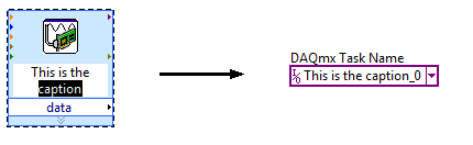
Task of naming of the DAQ Assistant
I not bad by using DAQ Assistant to create a task to do what I want, but I can't understand how to give a meaningful name to the task. The name of the task seems to be assigned arbitrarily to something like "Assistant_1 DAQ", which is not very useful for me.
Please advise on how, in the "convert to NOR-DAQmxTask", procedure I can assign a different name to the task. If not, is it possible to rename an existing task?
Hi wildcatherder,
There is already a way to set the name of the task in the present case, but it is not quite obvious and has a little whim. If you change the legend of VI DAQ Assistant express before selecting "Convert to the NOR-DAQmx task", he uses the legend that you specified as the name of the task in Max... and then he adds "_0" at the end:
If you have a suggestion to improve this feature, perhaps you could post it to the Exchange of ideas, information Acquisition?
Brad
-
DAQ Assistant don't update the buffer size to change the frequency
Hi all
I use DAQ Assistant inside a loop to write a signal in a module output best 9262 OR a cDAQ-9174. I generate the signal with the express vi simulate Signal or with a simple loop using indexing. The problem is that when I change the frequency, using the same sampling frequency, I have a different number of samples to write the cDAQ does not seem to update the size of the buffer, so no my signal gets written in. The result is the first sine wave is nicely written, but each after that gradually get cut off on the edges. I traced imput signal that I generate, so I know that it is generated with the right size and frequency of departure, what ever it is, still works, it is those more later in the loop who have the wrong size aparently buffer. I tried to reset the cDAQ by adding a different DAQ Assistant at the end of the outer loop with the stop bit the true value, it makes me just the error "resource not available.
Any ideas?
I'm using LabVIEW Base development system new V12.0 32 bit.
Thank you
Matt
Idea:
Get rid of the DAQ assistant and use the DAQmx API. The DAQ Assistant is there to support the limited functionality and base up a dirty experience and running quickly. The report of the API offers more funcionallity and DAQmx property nodes allow greater flexibility. DAQ Assistant is just too limited for your needs. (you can't paint a masterpiece with crayons)
-
Recovery of the DAQ Assistant data acquired
Hello
I'm currently dealing with a continuous data using NOR cDAQ-9174 proposed acquisition and recording of analog input signals of a built-in three-measuring probe.
I built a simple vi using DAQ Assistant to acquire data and write to an output .txt - rather than .tdms using Signal Express.
On a day 10 cycle of data acquisition computer was mistakenly turned off - leaving the empty output .txt file. LabView recovered the VI cut and I wonder if there is a way I can access the data that has been saved by the DAQ Assistant which can be saved in temporary files etc..
I have no idea where that might be, since you cannot delve deeper down into the 'levels' of DAQ assistant as you would a sub - vi.
Just as a note aside to apologize my stupidity - I realize that all the data at the end of the writing task is stupid and completely avoidable... but I worked for a date limit.
Thanks in advance for any help you can provide.
Dan
The most likely answer is not, unfortunately. It looks like you were a table of data at every point of the construction and then measure he writes at the end. In this case, unless you have explicitly recorded data in a temporary file, it is located right in volatile memory, waiting for you to do something with it.
I realize that this isn't what you want to hear, as it comes to the time of submission of draft / year...
If you post your VI (preferably version LV2012 or below), I can have a look to see if there is anything obvious.
-
DAQ Assist reading bad voltage
Hello
I use the DAQ Assistant VI to read a voltage analog input of a card of National Instruments PCI-6221. I read the AI0 pin voltage. I provide voltage directly on this pin of a continuous feed, but the measurement of voltage obtained from the DAQ Assistant is incorrect: it seems to be reduced by a factor of about 1/3. For example, if I have 4 volt power to pin AI0, DQA help bed 1.43 Volts. I used a multimeter to confirm that the voltage on the PIN AI0 is actually 4 Volts and I know that the problem is with my LabVIEW program and not my diet.
Here are the steps that lead to my problem:
1. in the block diagram, I insert a block DAQ Assistant.
2. in the Properies of the DAQ Assistant, I select an analog input-> voltage
3. select channel ai0
4. I click "test" to test the channel
5. the tension is indicated as being 1.43 Volts, although 4 Volts is provided to pin (this is confirmed by a multimeter).
6. to ensureI click OK to complete the configuration of the DAQ Assistant. I run the program and draw blood. The graph also 1.43 Volts.
Does anyone have an idea why this can be produced. I have spent a good 4 hours trying to diagnose this and haven't found anything.
Thank you
Alnaif adnane
It's normal. Do a search for the topic "ghost".
Maybe you are looking for
-
Problems with iTunes library shared between 2 computers
I have a rather unique situation where I have a single iTunes library that is shared by both computers. It has worked well for years, until lately. Here is my configuration: Mac iMac server software. All my music is on a USB drive 3 TB (named 'music'
-
AutoComplete history shows only the favicon: URL is not displayed
FFox 26 on Win7 Pro (Dell)All of a sudden (with new FFox?), we do not see the URL displayed in the history of the auto-coimplete. We get a drop down menu, but only the sites favicon is displayed: space to the right of the favorite icon where you shou
-
Best approach and Apps to manage Pix taken on the iPhone and sync.
Can someone direct me to articles or the spirit to give me a quick post re: a great way to manage my pix that I take on my iPhone 6 then organize into folders easily and have the synchronization of files to my other mobile devices and Apple computers
-
Photosmart D110: Photosmart D110 don't wake up
My HP printer will not wake up to print from my computer. If I restart the printer, I can print from my laptop. I can get one or two impressions, but if I wait a while he won't wake the printer to print. The printer is connected to my wifi. Can I pri
-
Profile of transfer of Q5 Q5 to Q10 blackBerry
Hello I have problems of transfer of my profile to my current profile of a Q5 to a new Q10. Both devices have the latest version of the software, but he says it's incompatible software device annd so is not possible because the software in the Q5 see