VHDCI to VHDCI DAQ cable
Hi all
I need to connect our DAQ SMU-6368 maps to a personalized e-card.
Due to the dimensional constraints, we need to use VHDCI connectors to the custom Board.
Thre is a data cable for it?
We have seen that the SHC68-68EPM cable start with VHDI of data acquisition and end with a SCSI 68 pin on the other end.
We need a straight through cable in which both ends are VHDCI.
For boards of HS-DIO is available the NI SHC68-C68-D4 cable that meets our needs but, as I understand it, it is made specifically for HS-DIO and is not suitable for the use of data acquisition.
It is available on a good cable VHDCI-VHDCI DAQ of NOR?
Thanks for your response
Hi Luigi,
You can also consider this one.
I hope that helps!
Bye,.
Licia
Tags: NI Hardware
Similar Questions
-
Meilhaus 3106 MAX/DAQ Assistant questions
Hello
While I'm sure that you all have grown tired of my usual throat-clearing, I'm a relatively inexperienced developer, so apologies in advance if this question is incomplete or missing otherwise.
I recently got a Meilhaus electronic RedLab 3106 DAQ. Box manual is at: http://www.meilhaus.org/downloadserver/redlab/manual/RedLab%203106_en.pdf
Attempt to use this device after completing installation 'Quick Start', I discovered that the data acquisition was not read by MAX (v5.0). In addition, by attempting to use the DAQ Assistant, in LabVIEW 2011 for this box DAQ (which I did successfully on this machine with a DAQ USB of NOR-6008), I discovered that the device is not listed with the text "no taken physical channel supported" that appears when the registration of the channel would be generally.
Normally, I try just a reinstall of the drivers/software 3106 package, but the strange thing is that Windows (XP - SP3) gives me the bubble 'New hardware found' when the USB fuelling the DAQ cable is connected to the computer. In addition, the acquisition of data can be read by a program that came with the acquisition of data called "InstaCal", including an order to make the power led on flashing box. Finally, a universal library, which also comes with the DAQ hardware has itself installed successfully in LabVIEW under "User Libraries". Given this feature, I am convinced that it is simply not possible to use the DAQ Assistant in LabVIEW for this particular data acquisition or that there is something in LabVIEW/MAX in need of fixing.
Someone knows a problem similar to this with the 3rd party hardware (ideally, Meilhaus) and software of NOR? If so, how do fix you it?
Kind regards
MG Wilkinson
Material acquisition of third-party data is not supposed to be detected by MAX or used with the DAQ Assistant. Thus, simply use the functions you provided.
-
Divergence mapping SH68-68-EP.
I have a DAQ cable type SH68-68-EP, manufacturing P/N 184749 B - 02, catalogue number 184749-02, which has 68 pins at each end connectors. I cut this cable in two to make two DAQ cables customized with the 68 on one end and a connector on the other. I use the file SH68-68 - EP.png for the color of the wire to the PIN mapping. I noticed an anomaly - the file said that 40 pin must be connected to a yellow/green wire, but it is indeed connected to a brown/green wire.
This would not notice if you have opened the cable to reach the individual wires.
Kind regards
Neville
Neville,
You are right. I checked the internal documentation and the 40 pin must be connected to the brown-green wire. There is an error in the file SH68-68 - EP.png. Thanks for the comments.
Concerning
-
USB-6225 DAQmx measurement problems when using a voltagesplitter
Hi guys

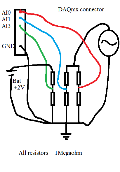
I had a serious problem regarding the use of DAQmx USB-6225. Please look at my diagram below:
When I measure the waveform sine on AI0, everything is OK. Even with a very sampling rate high as 80kS.
When I measure the waveform sine on AI1, everything is OK. Even with a very sampling rate high as 80kS.
When I measure the battery voltage on AI2 CC, everything is OK. Even with a very sampling rate high as 80kS.
Now comes the problem:
If I measure all three analog inputs or the two and two together, I get a very different result when I measured one and a single channel. If I add more channels (i.e AI3 and AI4) on my USB-6225 DAQmx, without connect anything to them, I can see the sinuses even as I do with AI0 AI1, but with less amplitude.
When I measure the voltage as well as AI0 and/or AI1, the domain controller becomes sinus armor as well. If I connect the + 2 V DC directly to data acquisition without resistance, I see a line perfectly DC on my chart, but with the sinus AI3 and AI4 top.
If I use an oscilloscope and measured directly on the same wire that goes to my data acquisition and the resistorcoupling, I can see small pulses of the samplingfrequency and the signal seems quite noisy.
That's my big problem:
Everything works perfectly if I use R<100Kohm. any="" value="" below="" 100k="" is="" ok.="" this="" coupling="" on="" the="" schematic="" is="" just="" a="" test.="" the="" trouble="" comes="" when="" i="" need="" to="" measure="" a="" circuitboard="" that="" draws="" energy="" from="" a="" capacitors="" in="" the="" circuit.="" if="" i="" use="" any="" resistors="" below="" 1megaohm,="" it="" draws="" energy="" from="" the="" circuitboard="" and="" the="" test="" is="" not="">
Anyone with some experience around this problem? The impedance of the analog input on my USB-6225 DAQmx is 10Gigaohm so it should not really been an issue.
Here is what I tried:
With the help of a D - sub cable with shield. I tried to use with no shield shield closed, I have both ends and closed, the shield only on my DAQ.
I checked my code and also just used the DAQ assistant.
I checked all parts off my setup for groundcircuits and I twisted each cable from any power supply, the signalgenerators, the DAQ cables.
I have connected my DAQ to mainsground (in the wallcontact 230V and Yes, we use 230V in Norway). Also any other equipment.
I connected without mainsground. Also any other equipment.
I tried cables as short as possible.
I tried to use the differential, CSR (Respect to GND), NRSE (Respect to the sense of IT). Nothing has worked.
I tried to use as sample rate and samples possible. (It helped a little when the DC measurement and AN analog input. If I tried all three, he has yet again).
All this comes to mind that the USB-6225 DAQmx cannot manage measuring more than resistors with values around 1Megaohm and above.
The answers will be rewarded with congratulations and a sincierly 'Thank You '.
Hi guys again!
Bother replying this thread

I'm a guy. I don't read manuals! But now that I did... And. There are 4 pages describing my problem and what to do about it. So problem solved
I have experience ghostvoltage of the other channels due to the high - impedance of the source. I created a follower of tension with an op-amp and the problem disappeared! Thank you ni.com/info/f/. Do you have answers for everthing is there to inquire. Except why I ran out of beer. mmm beer!
-
How can I check each pin of the connector VHDCI SMU-6548?
I need to use the VHDCI interface on the slot 3 i.e. NI SMU-6548 NI SMU-1062 q for testing purposes. I need raise or lower the individual lines of the 68 lines available. I use the VISA to do?
If no VISA, how are NI - HSDIO which are available with the help of LabView 2009 to do? MAX test Panel specifies the channel 0-15 and 16-31. How these channels is linked to 68 lines?
-
display only documents I found of the 655 X 654 X. Need to know to 6536. THX
Hello
Please click on the following link and download the latest Help file for the 6536:
http://digital.NI.com/manuals.nsf/WebSearch/DDAE1CEC74DFA3C48625750B007A1A53
In the included help file, click the 'Connection signals' page in the content for the pinout.
Thank you
Keith Shapiro
National Instruments R & D
-
What is the difference between the external SCSI cables and cables data acquisition
Hi all, I would like to make a simple extension using an external SCSI cable and a NOR 184749/SH 6868. In other words, it would be: female HD68 bolt of the cable ends OR coupled to an external SCSI HD 68 male with a VHDCI 68 male cable. What are the differences between the external SCSI cables and cables as the (M) 6868EP of the CHS data acquisition. Other than the sex of the end of HD68 is usually on one. How is the posting hit buy using an external SCSI cable for an extension to tell a BNC-2090?
Yes, I realize that NEITHER wants us to buy their cable, but in these economic times difficult, to do use all available resources, so I have to try,.
Thank you
joelowwatt
Hello
As long as you have compatible connectors, SCSI cables will work DAQ of basic functions. They have the advantage of NO cables is that we can meet our DAQ hardware. So, we can create pairs twisted differential pairs to HAVE, using the ground for shielding terminals and generally specialize the cable to minimize noise and crosstalk. Because the SCSI cables are not specialized, you are likely to see the most noise and, if you go the sampling rates more Rapids, crosstalk. If you are in a laboratory or factory with a good amount of noise EMF that your readings are not quite as clean, or if you have fluorescent lights you might see 60 Hz noise you might not see otherwise.
If you want more details on the specifications of the SH68-68-EPM cable, I recommend these two articles. The first example of the twisted pair and the principles of the SH cable shielding and the second gives the most precise specifications that you can compare with when looking for a SCSI cable.
3GRD4C33 Knowledge Base: mapping list of the sons of SHC68-68-EPM & SH68-68-EPM cable
1TGEHPDM knowledge base: detailed specifications for the SH68-68-EP cable
Kind regards
-
Replacement cables SHC68-68-EPM?
I have a PXI-6363. The recommended cable is the SHC68-68-EPM cable. I have one of these practices, but need 2. I found a couple of unused cables carrying around (NI SHC68-68 - RMIO & SHC68 - 68 - RDIO). Can I use one of these as a substitute for a cable EPM?
I am not convinced that you can simply replace them and if they don't work it wouldn't be ideal. On the one hand, the SHC68-68-EPM cable specifies that it ends by a shift of VHDCI 68 pin, while others are just VHDCI, but I was not able to find information about the difference. In addition, they list compatibility for X and M series for RMIO or RDIO cable. While they are all 68 pin cables there are huge differences in grouping and shielding wire, and they are all optimized for different features/data acquisition cards. I found the mappings of wire for the EPM and RMIO which illustrates this.
Wire mapping list to the SHC68-68-EPM cable
http://digital.NI.com/public.nsf/allkb/DE2D842E545DE64B86256F78006EAB1A
RMIO cable Wire Mapping
http://digital.natinst.com/public.nsf/ $CXIV/ATTACH-AEEE-88AQJT/$FILE/SHC68-68-RMIO.png
-
The MID-7604 puts a lot of noise, where can I get cables isolated for it?
I use a motor driver stepper MID-7604. I want to reduce the ground loop noise in the system that I'm able on my PXI-5152 (through a series of sensors, etc.) using an optical isolator or transformer for cable VHDCI 68 pin that connects the engine to the computer. Such a thing exist, or are there other methods to mitigate the noise? I'd rather have the computer connected to the same circuit and the MID-7604 / I don't really want to buy a gigantic isolation transformer/surge protector to plug into the MID-7604.
bravedonxiote,
PXI to the ground connection should be fine, so everything is referenced to the Earth.
And Yes, grounding of the table is a good idea as well.
-
I need Custom make a cable for connector PCI-6281 (M series). One end of the cable has a connector, 68 pin VHDCI; the other end is just free. I bought one of National Instruments SHC68-NT-S cable, such as recommended on the web site for custom connections.
I just realized that the twisted cable pair follow assignment of the pins of the connector! There are a few analog inputs (e.g. AI0 and AI8, etc.) which are twisted together rather than be twisted with their GND terminals.
I know it takes a larger cable and a little manual labor to make correctly matched but there at - it such a cable available?
I look forward to your responses.
Frank
Hello, Frank.
Unfortunately it is not a cable with this description because each cable is twisted with the corresponding PIN just next door. As you probably already have it, you can check this link for the labelling of all what you son for not confuse:
-
Number of channels high: multiple markets good Renault vs expensive DAQ unique?
I need 4 analog outputs but the resolution is not critical, the USB-6008 low-cost housing will suffice. Is there a reason to buy a more expensive DAQ (like the USB-6351) with many channels against multiple cheap 6008?
Appears to be a bad practice, but I don't see why...
I did the systems in two ways.
Pros to DAQ more expensive: the single connection, only device to implement to the MAX and like johnsold said, usually get you better resolution, precision and timing out of it. On the other hand, of course, cost... but also the physical size.
With several small Renault, in the production of benchtop equipment, this means more USB ports on the side, or the use of a USB hub. More ports means more cables and anything else for the manufacture of screws with. USB hubs may cause problems on some computers, and usually the first thing I get when troubleshooting.
Backwards, you save a lot of $ buy two or three 6008 150/ea vs a bigger 6343 to 1500/ea.
If you use a USB hub, you can get something like this Startech unit. They have a value of the price difference in quality el-cheapo consumer centers. Good thing that one is if you have decent 12v in your system power supply, you can feed the hub immediately that and use a USB port as a supply of 5V/500mA for relays/LEDs/etc your DAQ (s) hunt.
-
SH68-c68-S cables and SHC68-c68-S are interchangeable?
The SH68-C68-S cable is specified for the UMI-7764 interfaces and the SHC68-C68-S is specified for the UMI-7774, but these cables are both compatible with the UMI-7774?
Thank you.
Hello
Although the cables do not seem to be very similar, it is not recommended to use these interchangeable cables. The main difference is in the internal wiring. The SH68 cable is also used for the DAQ cards and have a common ground, which can create problems with the maps of cable movement. The following knowledge base articles provide more information and specifications.
[1] What cable does with my gear OR Motion?
can [2] I use a cable movement with a M Series DAQ card?
Kind regards
Huntington
-
Hello. I just reinstall Labview 8.2 and I do not see simulation devices in Max MAX is 4.2. All I can see cable RTSI. I used to have simulation devices, but I also installed LAbview 2010 before eval. After the complete reinstalled I can't get it back. I tried several times. When I install new DAQmx (I think than 9.1), it installs simulation devices, but then I lose my vi.lib DAQ - mx directory (don't know why).
Based on the info from NI Labview 7.4 and above should have simulation devices. Any suggestions?
I use Win 7 64 bit.
Thank you
Thank you. I think that we get no warning because 8.2 supported by Vista, and that's probably just enough good pass install Win7.
-
inductive proximity sensor with DAQ
Hello world
I'm planing to connect my inductive proximity sensor with DAQ of NOR-9215 but won't be sure this thing work perofectly. Also I do not know how to connect my sensor with the BNC Terminal.
The sensor that I use is Automation direct AM9-05-1A with a voltage of 10 to 30 VDC and output voltage of 0-5 VDC range.
I want DAQ to monitor my output signal of the sensor.
It seems that you have two choices.
1. cut the connector from the sensor and cable drivers appropriate for a piece of coaxial cable with a BNC connector plug (and separately to the power supply).
or
2. get a socket that fits the plug sensor cable and its terminals to wire to a coaxial with BNC Plug cable and power supply.
Lynn
-
DAQ 6014 connection with sensor
I have a PCI DAQ 6014, a connection block 68 pins, a DAQAccessory. I want to take the signal from the sensor to the PCI 6014 Iconnected sensor output on the terminal block, then block thisconnection via a cable connected to the 6014 correct? signalfrom voltage sensor, the output pins two-wire in any block of connection. I put in ACH0 and AIGND possible? I don't understand to do data acquisition accessory. its function is like. I don't may not need to use it in this case is not. I thank he replied.
Hi saker.
The standard way to connect your system will be: connect your PCI on your computer, use the cable to connect the PCI card with the accessory and finally your sensor to the accessory.
If your sensor is a two-wire sensor, there are two ways to connect to the map, the CSR and the differential mode, you can find instructions and descriptions on this type of connections on page 2-5 of the manual you can find here. In page 2-21 of the same manual, you will find connection CSR instructions both in differential mode.
So, if you accessory is the SCB-68 box, you might find the pins of device mapped in figure 2 on page 3 of the user manual. This means that the pins in your card will match the pins in your Terminal.
Hope this information helps.
Kind regards
Maybe you are looking for
-
I need information about Satellite C850
Why can't I find information on 'satellite C850 - B717, B718, B719, B720.This Toshiba site, what is the problem?, I found information for other C850 models, but not for the one I mentioned.
-
I have a M7-1015dx that has a backlit keyboard, but there is no light coming for the touchpad, this model has the light for the touchpad? If this model is supposed to have a light around the touchpad can you please make me no way to turn it on? Thank
-
An analysis of the USP flash drive is essential to insert into the computer.
I need to scan my Flash USB drive when inserted into my computer. I have Windows XP Home Edition and Microsoft Essentials as my virus prevention program.
-
OK, so I just noticed that the pilot attention sign / troubleshoot sign. Internet works fine, I use the same laptop to download the image. Anyone know why this is happening?
-
Cisco ACS. Two-factor authentication.
Hello. We intend to use the connection diagram: cisco asa + cisco acs 5.4 + rsa securid.We use two groups on Cisco ACS. Group "A" must use two-factor authentication, and the 'B' group don't.How to create this rule?