6536 VHDCI connector pinout
display only documents I found of the 655 X 654 X. Need to know to 6536. THX
Hello
Please click on the following link and download the latest Help file for the 6536:
http://digital.NI.com/manuals.nsf/WebSearch/DDAE1CEC74DFA3C48625750B007A1A53
In the included help file, click the 'Connection signals' page in the content for the pinout.
Thank you
Keith Shapiro
National Instruments R & D
Tags: NI Hardware
Similar Questions
-
HP Z620: Front panel connector pinout
Kindly help me on what is the pinout of front panel to motherboard HP Z60 connectors? Nothing is indicated on the map.
Here is the motherboard front pinouts. This is a view of the motherboard. PIN 6 is the key, a missing brooch, which helps determine the orientation of the connector.
The Z420, Z620, Z820 and all have the same front panel connector pinout.
-Terminals 2 and 4 are for the power light. HP systems have back to back LED connected between these pins. A white LED lights up in red and a normal functioning (and flashes error codes) when there are errors.
-Connect a switch momentary between pins 7 and 8 will turn on the computer and off.
-The sensor pins are for a thermal sensor in cable from the front panel. If it's sensor is not installed, the system fans will probably ramp at full speed and very noisy.
-Speaker Out is the internal speaker.
-
Equium 80 - 132 has PSA87E - the LCD connector pinout
Can someone help me or direct me to a site (if not here :)) where I can find the pinout of the connector from the motherboard to the LCD from a satellite
with
model name: EA80-132
Model No.PSA87E - 0030069KHello
I tried to find all the manuals but unfortunately without success. If you search for the connector on the motherboard where you can plug the display cable, it should be placed somewhere in the middle. When the keyboard is removed check connector in the upper mid position (tails).
Sorry, but I wasn't able to find any nice document with screenshot. In any case I hope that you will be able to find the right connector.
-
HP Pavilion p6 - 2220t: motherboard layout and before panel connector pinout
Hello
I need the layout of the motherboard for the TX of H-Cupertino3-H61-ua (Cupertino3).
This page:
http://support.HP.com/us-en/document/c03329092
available and the legend are missing. I need to know the pinout of the connector cover (power, hard drive, etc.).
In all cases, a link to a detailed repair and maintenance manual would be a great help.
Aloha!
It would be of no use?
-
Z800 P5 (front) connector pinout needed
Hello
Anyone happen to know the pinout of the P5 connector on the motherboard? Is the one who has the power button, HDD LED etc. and it is the only one not vented in the maintenance manual.
I do a bit of a project long term to fit a card mother z800 in a case HPTX and this information is crucial. Have owners here traced the sons of this connector in the front?
All the information are welcome.
Kind regards
-Andy
Well it turns out that the pinout for P5 on the Z800 seems to be the same as on some of the earlier advice. The pinout documented in this post on the forum works for me, at least for the switch/power LED LED/HDD:
I actually now had all of the operational Board in a case of HPTX form using a standard power supply standard and HSF on the Xeon factor. I intend to make a full report soon on my website for the benefit of anyone else who wants to play with this powerful card.
-
The front panel ThinkCentre M81 connector pinout
I have a ThinkCentre M81. I am currently trying to put the guts of it in another case, so that I can add some more to it. I checked all the guides I can find on Lenovo's Support site and they show only the location of the connector and how repalce the façade.
I try to connect the connections for the front panel ATX standard for my motherboard M81, which I'm having trouble with, reason for the connector of the Panel before Lenovo comes to be a big connector.
I wonder if this information is a resource that I missed somewhere, or if I have to trace the wires.
It is not your model, but maybe they are similar:
-
HP Z620: Problem of auxiliary graphic workstation HP Z620 pci-e power connectors
I want to fit my new GPU Z620 workstation card. I see that there are two auxiliary pci - e power connectors on the plastic support. I intend to use these two to put my new graphics card but I see potential problems.
The problem is that in these two connectors pinout is not really to PCI-e spec. There are five female terminals to each 6 connector routes. The three terminals in the top row are crushed and two terminals downstairs is 12V. 6 cavity is empty in both connectors. As far as I know the PCI-e power connectors should have 12V power supplied to cavity n ° 4 and n ° 6 of cavity. What I have to manually change these two connectors pinout and move terminal 12V from cavity to cavity no.6 no.5 or there may be a few HP adapter that could solve this problem?Only HP knows what HP has designed (and why) and as such, it cannot be assumed simply that a connector on a system is consistent with the 'standards' and not a "psudo owner" Connector (as seems to be the case with your PEG connector that is missing pin #3).
Normally, a PEG 2 connector x 3 can provide 75W and as such, each 12V pin provides 1/3 of the power budget. This means that the HP "psydo owner" PEG connector, for lack of a better term, may not be able to supply 50W (if each ping is kept for the same current capabilities used in the standard 2 x 3 plug PEG).
Then, this suggests the Z620 can only support a 175W graphics cards (with 75W of PCIe + 50W of each of the two 2 x 3 PEG connectors). Note that the standard allows graphics cards to 225W pulling 75W of the slot PCIe and 75W of each PEG 2 connector x 3!
Thus, quantify this is to watch the quickspec for your Z620 and see what graphics cards are certified for use with your system. Then to know what cards are certified for your system, you can check what PEG connectors as appropriate are provided on these certified cards and also check what is their energy consumption. I would guess that all graphics cards that require more juice 175W has not been certified by HP...
Since you say your card draws 165W, this budget of power seems OK during examination of the foregoing. So it should just be a matter of connect the two connectors of the PEG 2 x 3 and all should be well.
However, it you want a card more powerful, purely based on the fact that a standard 2 x 4 connector PEG can power 150W using three-pin 12V, this would indicate that each pin can supply 50W. Assuming that the pins used in a conector of PEG 2 x 3 and 2 x 4 are the same, a 2 x 3 with only two pins 12V power connector could in theory provide 100W each. So you could in theory use a 275W card into the PCIe slot with your 2 psudo owner HP PEG connectors. BUT it means something to the pins themselves and that your HP power is up to the task (and can actually provide the necessary 275W power).
And I would say that if you wanted a graphics 225W which is supported by standards, likley it would be a simple mod to the rider 12V among the pins for the vacancy that is normally used by the 3 pin (12V). I'd be surprised if the block POWER HP of power and wiring could not handle the necessary extra 50W. But maybe it's a little too much for some who enjoy the guarantee.
In any case, without owning a Z620, I would be comfortable in saying that you have no problem with this graphics card 165W and these exclusive hybrid psudo 2 x 3 PEG connectors as is

(Heck, I don't got no problem with a 35W graphics card in a slot PCIe capable of 25W of my Dell T610 server that only supports the graphs via the inetgrated adapter)...
But really, who knows why only two used HP pin 12V in their PEG connectors, maybe they used the best quality PINE and they were not sufficient for the cards, they chose to certify. Maybe save 2 cents for a less pin was a driving force... HP only knows what HP...
-
Hi all
I need to connect our DAQ SMU-6368 maps to a personalized e-card.
Due to the dimensional constraints, we need to use VHDCI connectors to the custom Board.
Thre is a data cable for it?
We have seen that the SHC68-68EPM cable start with VHDI of data acquisition and end with a SCSI 68 pin on the other end.
We need a straight through cable in which both ends are VHDCI.
For boards of HS-DIO is available the NI SHC68-C68-D4 cable that meets our needs but, as I understand it, it is made specifically for HS-DIO and is not suitable for the use of data acquisition.
It is available on a good cable VHDCI-VHDCI DAQ of NOR?
Thanks for your response
Hi Luigi,
You can also consider this one.
I hope that helps!
Bye,.
Licia
-
EqualLogic PS series console RJ45 cable pinout
Hello world
I have an Equallogic storage array to use for the test which I believe is a ps100e, with two controllers blue sata ports having back series RJ45. Nothing I've used so far has had any kind of traffic from them, then someone can help me with a pinout of the console cable that was included with the devices? (I got was the machine itself). I saw a few summaries puts online buy them, but I'm a bit of a hurry and don't have much of a budget, so I was hoping to do so they are considered non-standard.
Thank you!
Here is the pinout settings and baud. Make sure that this flowcontrol is disabled on the serial port.
We find this info on the site Web of Equallogic.
The title of the solution
Cable to the serial Console, identifying Type I, II controllers, the RJ-45 connector pinout
Details of the solution
Type 1:
FRU PN IS 95-0444. Cable 'dongle' will have a white label with 51-0003-02 marked top. It is 10 inches long, black, with DB - 9 (M) money and a micro DB-9 at the other end.
You can order the dongle as a Molex 83421-9052 reference number to search on google. You will also need to a modem cable Null to go with it, if you don't have one, easy to find, even the most Radio Shack has them.
Type 2:
FRU PN 95-0517. Cable will have a white label with 51-0008 marked top. It is 10 feet long, black with the RJ-45 at the other end and a DB-9 (F)
Here is the pinout of the connector RJ-45 series of EqualLogic Type-2 (SATA 2 command Module):
1 - DTR (out)
2 - CTS (en)
3 - chassis Gnd
4 - RxD (in)
5 - TxD (out)
6 Sig Gnd
7 - RTS (out)
8 - DSR (en)
In the current firmware versions we do not deliberately set, or answer, the control signals (DTR, CTS, DSR, RTS), then you must either configure the device you connect so that it ignores them, or provide telesignalisations the according to the needs.
The series settings are: 9600 baud, 8 bits, 1 stop bit, no parity, no flow control.
-
Does anyone have the list of pins to make a Seraglio of cable to connect a pc to the switch LINKSYS SPS224G4?
Thank you!
Hello
The SPS224 console cable must be the same as the older the SRW series switch
OK, I took out my multimeter and checked the list of pins on my cable from the console that I use to connect to my SRW2008P.
My cable SRW2008P console on the two DB9 female connectors pinout is 1 to 1.
In other words easily DB9 female-female cable available with the following pinout.
1-------------1
2-------------2
3-------------3
4-------------4
5-------------5
6-------------6
7-------------7
8-------------8
9-------------9
Best regards, Dave
-
Type R61 14.1 "1400 x 900 screen corruption 7738-CTO - please help troubleshoot
Hello
I picked up a CTO 7738 used on ebay. Since this is a CTO, here are a few characteristics:
T7300
3 GB
Intel GMA X 3100
14.1 "1400 x 900
Webcam
Bluetooth
FireWire
fingerprint reader
Intel 4965AGN wireless
He arrived in a State of good but not a Virgin. I ran memtest86 +, physical fitness test, for Hitachi hard disk and PC Doctor tests all passed. I have not found any dead pixels. Convinced that he was in good condition, I did the following:
- Cleaned and plastic keyboard with isopropyl alcohol soaked cotton cloth.
- Clean screen with microfibre cloth moistened with wally world without glare cleaner, lens 'formula without alcohol.
- Exchanged in a Thinkpad (Atheros) 11 a/b/g WiFi card to a Type 8932 15.4 "R61. Follow the procedure described in the hardware Maintenance Manual, which is to remove the keyboard and palm rest. I unplug the Palm, just tilted up so could remove the keyboard (I unplug). Used a pattern bracelet while had open machine.
- Dust sucked off the fan using the brush on top of fan and fixing of radiator plastic (high speed) on the vents.
- Dust sucked out of various other interior spaces using the fixing of radiator plastic.
Everything seemed fine after that.
Then, I installed Windows XP 32-bit, Norton Internet Security 2009, Internet EXPLORER 8 and Firefox. No problems.
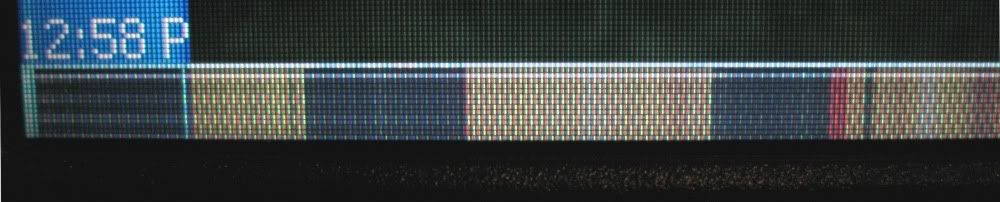
A few hours later, I installed upgrading XP SP3, that I had downloaded a year ago. At some point not long after installing SP3, I noticed the taskbar looked weird:

And pixels background 20 or so have been ruined since then. They do not always look the same:

Running Memtest86 +.

White screen (PC Doctor)

Black screen (PC Doctor)

Flashing the BIOS
The model changes over time when you're sitting just slowed under XP or Configuration of the BIOS. But I can't do the pattern change in:
- Change the angle of the screen, almost closed flat.
- Bending / pushing the slick LCD (with keyboard moved out of the way).
- By pushing on the LCD ribbon cable connector.
- Push the connector on the keyboard.
- Move the keyboard around (Flex ribbon cable).
- Based on the bezel of the screen.
- Pressing the back of the housing of the display, it deforming slightly.
- Pressing radiator covering the North Bridge.
Here's a closeup of the bottom left of the teletubbie XP screen (with the taskbar vertical on the left). The only line of pixel bright in the upper part of the band of corrupt Exchange when I drag windows autour - it seems to mirror the row from the top of the screen. The rest of the band seems that vaguely related to what is on the screen (see black spots under some elements of the taskbar in the first picture), but does not change when I drag windows autour.
Google turned up this post about a similar problem. I tried:
- Removed and replaced the LCD Ribbon connector cable (twice).
- Keyboard not plugged and re plugged.
- Flashed the BIOS to 2.14 old then back to 2.26 last.
None of these answers seem to change anything.
Everything else on the machine works. Video DVI to external monitor is fine. The Atheros WiFi card that I swapped in the works. I have re-ran Memtest86 + and PC Doctor tests and they all still pass (except video interactive!)
Some ideas of possible causes:
- Cable sheet pinched LCD? On this machine, the metal bracket that holds the card connector mother LCD ribbon cable on the framework has a step down where it will fit on the card WiFi support. The step to support causes at the edge of the LCD tablecloth to bend down. When I tightened the screw left WiFi card, which doubles as the LCD ribbon cable support live right, I wonder if I pinched the tablecloth? Or maybe squeezing the keyboard pinch the ribbon cable?
- Watered LCD screen? I did clean up around the edges of the screen. Maybe some cleaning fluids worked his way behind the bezel of the screen and the devastation?
- Dust, something shorting? Aspire inside caused some dust to move around, perhaps in unfortunate locations?
- Shock damage? If UPS moved the ThinkPad (shipped in its original box) on its way to me?
- XP SP3 killed my ThinkPad? (!)
- Pre-existing condition? Seller says that everything worked well they could say.
- Something else?
Would really appreciate troubleshooting tips to those of you with experience with this kind of problems.
I want to fix the problem myself if possible (the system is out of warranty). I'll spend the money if I have to, but do not want to replace the screen only to find that the problem is something else.
Sorry for the length of this post, wanted to give details that could suggest a cause. And if all goes well a fix!
Thank you
Frank
I disassembled the strainer and I tried to unplug / re - connect cable from the LCD screen. Neither that, nor prick on the LCD cable has changed the symptoms. So I replaced the screen LCD, and that fixed the problem.
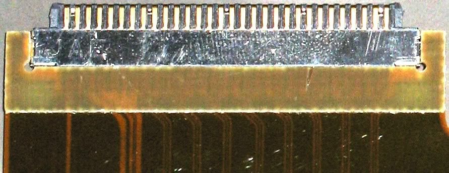
FYI, here is a picture of a little shabby close-up of the cable at the end of the LCD:
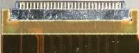
(click on the photo for an overview)
There are about 30 pins on the connector. The cable carries the video signal from the motherboard to the LCD screen using the standard FPD-Link of signage. (Inconveniently, there is no standard connector pinout, so the wiring of the cable depends on the exact LCD used.)
National Semiconductor has a nice page on the history of FPD-link, with comparisons/DVI. They say that "a single pixel 6-bit application using a...» Couples 3 data and clock requires the FPD-Link interface. "Looking closely at the R61 LCD cable, includes 8 triple track on the right side, more 1 triplet of largest trace on their left, 1 more track. I wrote the LCD (Samsung) manufacturer and asked a pinout of the connector, because I'm curious. But at this point, I'm guessing that each triplet trace is a thread to the front + wire + wire back half.
Bottom line point, I wanted to do, it is that the video signal is transmitted on a few threads of complex form cable, series. A problem with one or more of these wires should translate into visible corruption everywhere in the LCD screen. It is not like a single wire maps somewhere given the physical LCD.
So in case anyone having problems like I did, with video works well on a monitor external and everything looking good everywhere, but in a small area of the screen of the ThinkPad, you can be almost certain that the problem is the LCD itself.
-
niHSDIO dynamic generation and Acquisition using LV configure Trigger VI
Hello!
My experience is limited within the environment of digital programming; Nevertheless, I have worked on this problem for a few days and would appreciate some comments if possible.
I am trying simply to generate and acquire a duty cycle of 50% of 8 MHz TTL pulse train on a PIN DIO of the PCI-6541 and acquire back from the signal on another axis of DIO. I have a connector corresponding to the embedded 6541 VHDCI connector which of course the generation and acquisition DIO welded pins to provide a loopback effect.
In short, I use the niHSDIO configure Trigger VI (instance--> start Trig: SW), niHSDIO send software Edge Trigger VI and write Named Waveform VI (instance--> data: 1 D U32) in the generation section. For the section of the acquisition, in short, I use the VI of waveform Fetch niHSDIO (instance--> single record: WDT).
I see results in the waveform acquired showing the generated and acquired digital TTL pulse on the respective DIO pins train, but I can't seem to get my 8 MHz frequency requirement. In addition, the lower part of the assignment of pin DIO, more frequency. Unfortunately, due to the configuration system required, I have confined myself to pin 12 DIO for the generation of digital pulses. Even with a 50 MHz clock frequency, I'm ~ 6 kHz of frequency acquired max. I looked at changing the parameters of the wave form VI named write, but it is not possible because the VI call a library function node. I also tried to generate a waveform of 8 MHz through a VI of generator of digital model, but I do not believe, you can trigger on generated waveforms? It seems that you must generate data using a simple loop to as a counter and sending the result to the waveform VI named write. Are there other ways I can simply generate and acquire a digital signal of TTL of 8 MHz (no external connection)?
In any case, any kind of feedback would be greatly appreciated.
Thanks in advance for your time.
Dan
Dan,
Sorry about the nomenclature. I usually use 0 x or 0 b for indication of radix, it is not necessarily a kind of standard, just what I used in my old days of the Assembly.
Looks like you have a knowledge about the data. Basically the material is just save in DRAM an array of words of 32 bits, with each bit corresponds to a data channel and each element being generated to the sampling clock rate you enter to your vi. Everything else is just easy data manipulation or usage. The interleaving method is just as I like to create a toggle model. You can easily do a loop with an inverter and feedback node or use on the construction in screws to signal generation. In addition, you can use the software digital waveform editor or control panel test to generate the county or toggle modes.
Give us an update when you enter the laboratory and let us know if you encounter any other disorder.
-
LV FPGA workflow nested CLIP w / NI SMU-6591R
Hello
I develop an application on a NI-SMU-6591R Board. My installation also includes a SMU-1085 w chassis / controller 8135.
Goal: set up a VHDL project prior to the Commission of 6591R. Given that the application requires access to 2 ports Mini SAS HD and the VHDCI connector on the front of the 6591R (physical front) a CLIP nested is the only option here, isn't it?
I am quite new to the LV FPGA framework. In order to understand the flow of the whole project, I would like to launch a trivial VHDL design on the 6591R: a D-FlipFlop edge triggered w / Syncronous reset. I have attached the the D - FF and the wrapper of CLIP VHDL code.
I would like that (1) a little (LV::boolean/VHDL::std_logic) to pass the port D of the D - FF VI (name FDF/D) and (2) drive the LEDs of the Board of Directors according to the signals of outputs (FDF/Q and FDF/QB). Also, I want to read (3) the same outputs (FDF/Q and FDF/QB) back to the VI flying two Boolean flags.
Following the white paper OR, I have:
- Managed to create a XML interface of the import VIDEO Wizard, import the 2 files VHDL (D - FF and its packaging).
- Selected the ELEMENT created in the IP-level component properties window. The LV_DATA_IN (host2fpga) and LV_DATA_OUT (fpga2host) I/O appear in the project tree, under the CLIP icon.
- Created a new VI under the FPGA device with an infinite while loop. Inside the loop, I dropped the LV_DATA_IN and the LV_DATA_OUT e/s and connected with a control (to LV_DATA_IN) and two indicators (of LV_DATA_OUT).
First of all, why in a simulated execution mode, the behavior of the indicators is totally random? They are not connected to one of the connectors 6591R...
Linking the FPGA VI, he reacts to any change in the control LV_DATA_IN button... Why?
The design works as expected in Vivado both in behavioral simulations and post-synthese.
Before asking here, I tried to understand it on my own. I have read all the documentation that I found on campus (I got access to LV Core1, Core2, Core3 and FPGA course material) and on the internet.
What is still missing me?
TY for your kind help!
-
In the help file for the SMU-6537, there is an illustration of "Front Panel and connector pinout" and a table.
The illustration shows pin GND 8.
However, the table below shows pin 8 as a RESERVED pin, * not * a GND.
I design a Board to interface with the 6537. I massage pin 8, or let it float?
Hey Tom,
PIN 8 in the illustration should tell RESERVED and not mass, and therefore you must not connect. We will update the image in the next revision of the help file. So to answer your direct question, leave floating 8 pin (do not connect to it). Let us know if you have any questions or concerns. Thank you and have a nice day.
Kind regards
DJ L.
-
I need the list of pins for various connectors case-Strip pin, especially J24 but other multispindle those too.
Manual of Tyan S2915 Board for is a different version than that of poor quality that they OEM would be at HP for the 9400 and HP Tech Ref for the 9400 only provides pinouts for connectors well defined including pinout lie anywhere.
The connector of the Panel before xw9400 J34 (there is no J24) pinout, the mother, is map:
There are 2 key positions (lack of spindle) on pins 10 and 15. Use these empty pins to help identify the signals.
The pinout is very similar to other former workstations HP. A few tips:
-Pins 1 and 3 are for the harddrive activity led.
-Terminals 2 and 4 are for the power light. HP systems have back to back LED connected between these pins. A green is on and functioning normal and red lights (and flashes error codes) when there are errors.
-Connect a momentary between pins 5 and 6 switch will turn on the computer and off.
-Connection of a momemtary between pins 7 and 8 switch will force a system reset.
-PIN 9 is designated as + 5V, but it is powered by a 100 ohm pullup resistor to + 5V, so it will not provide a lot of power. FOR INFO.
-SPKR + and SPKR - are for the internal speaker.
Most of the other connectors xw9400 follow standards of industry, i.e. the IDE drive and floppy connectors.
Is there anything else you want to know?


Maybe you are looking for
-
I have about 11g of photos on my Macbook Air. They in office / my documents/photos. Finder shows also 15g of photos in my Iphoto library. Are they duplicates? Delete a game?
-
Why is this connection is Untrusted (error code: sec_error_unknown_issuer)?
I'm now getting this connection is unreliable on everything that I try to open. This site says to open the folder profile and stem from boredom. Where is the profile on a MacBook Pro folder?Mac OS X 10.6.8 It is my third day to try to resolve this pr
-
I have a GUI vi, which is a strange phenomenon that I have not met before. On a view tab that is located has a few picture controls the different display. PNG images, based on the parameters of program execution. In these photos, the controls are use
-
My Media Player is running in slow motion, how do I speed it up?
My Media Player is running in slow motion, how do I speed it up?
-
Self-recovery of the names of the song for her album/does not work
Hi, people, thank you for reading. I use WMP12 on Win7 64 bit. I'm ripping my CD to MP3 collection, while I'm doing another work. In 'Library' dialog 'Options' tab, I "Retrieve additional information from the internet" checked in the section 'Automat