Virtual simulation NI 9866
Trying to simulate the LIN 9866 module OR a compaqDAQ NI 9188...
In MAX, I am able to add a virtual cDAQ chassis, but for modules to add no NI 9866
I'm pretty up to date, MAX 15.0.0f, DAQmx 15.1.1 w/Labview 2015 64bits, XNET 15.0
I hope it is something simple, like I need to have a physical first?
jsietz,
You are not able to simulate the 9866 in MAX, that's why you were able to simulate the cDAQ but not to see the option of 9866 module. Is there a particular reason why you were wanting to simulate rather than use material?
Tags: NI Hardware
Similar Questions
-
I use PXI - 1042 s with PXI-8196 embedded, each with several PXI modules installed controllers. (PXI-2530, PXI-4070 PXI-6509 etc..)
Is it possible to connect somehow to a laptop that has LabVIEW installed, such that I can develop applications (on the laptop) to control PXI modules?
When applications are completed and compiled in executable files, they will be installed on the PXI controllers.
I don't want to do, is to install LabVIEW on each PXI controllers I have to develop applications.
Kind regards.
You can develop your application... virtually simulating PXI modules - sounds interesting, but how to do this? (Or is it a matter for another post?
To simulate the device go to MAX > right-click devices and Interfaces > NOR-DAQmx simulated device > select your device and enter ok.
... but if you were to buy a PXI MXI-Express kit you can remotely control the PXI chassis - I think that's what I was looking for. But wouldn't this "work around" the on-board controller and have the executable running on the laptop instead? Looking at the link you posted, it is worth further investigation
It will bypass the controller for development purposes, but when you have generated your executable you can just charge on the PXI controller and it will run without the need of the laptop.
Kind regards
-
ACI Cisco Simulator in a virtual machine?
I understand (http://www.cisco.com/c/en/us/products/collateral/cloud-systems-managemen... ) that this need for Simulator machine physical but all the world got it running on a virtual machine?
I use aci-Simulator - s dk9.1.1.1 .iso
I'm running it on 6.0 ESX and VM configuration is as below.
100 GB SSD
10 NW cards,
16 GB memory
8 cores
Even if get you this to install, it won't rise properly. The software is written in order to check the ID of physical product of the machine on which it is installed. If that does not match an expected value, the APIC fails to start properly - DME services begin voluntarily. You must purchase an APIC-SIM-S and install it on that. In manufacturing the APIC-SIM-S hardware is programmed with the right PID.
Mike
-
Behavior of virtual keyboard - Simulator version 0.9.1
I have problems with the virtual keyboard. Sometimes it grows my application upwards, sometimes it covers only half of my application, but I don't know what will be the actual behavior of the device.
Can someone please clarify whether the keyboard will indeed push to the top of your application? Otherwise, I'll have to build something that moves "the fold" top text boxes
Thank you
Try it in the Simulator current 0.9.3.
-
Simulating multiple virtual channels per physical channel
I have make steps high speed with several channels simultaneously and am wishing to be able to store the raw data and the version to the unique scale of the data both in tdms files. However, I am wanting to be able to apply properties for the versions on the scale and not scaling separately, mainly to keep the data clean and usable, as well as to ensure that in 6 months when we look at the old data to establish anything confused reports. I know that several virtual channels may be established by a physical channel, but then they must be played in order. Is it possible to simulate this process, or give an another stream of distinct to write to the tdms file properties?
First of all, media DAQmx LabVIEW 8.2 9.0 and later, so you should be able to use the new feature. That being said, for your application, it wouldn't work that well, since you are eager to keep the original DAQ signal so a new signal scale. This function stores the data as you would see in DAQmx Read. Information of scaling you apply can be performed by using a custom in DAQmx scale, but you 'lose' the original file (RAW). However, if you store the scale factor in the properties (as explained below), you could get back to the original data at a later stage (by dividing by the appropriate scale factor). If you buy 2.5 MECH data. / s, you can consider this solution in the interest of performance.
That being said, if you need signals separated for raw and scale, this feature might not do what you are wanting.
Therefore, in answer to your question immediately, if you want these signals to be in the same file, PDM, it's quite possible. Here are comments by looking at your VI to this effect:
1. on the PDM write call and son in a 'group name' such as 'Gross' or 'ladder '. Which splits the data properly to make it obvious what is what.
2. If you want additional information must be stored with the Group (as the scale factor), wire in your group name in the PDM Set properties VI you have and set the 'names' and 'property values' properly.
3 certainly, wire in the same refnum TDMS to all functions of PDM.
Let me know if you have other questions about it.
-
FSX Simulator, Cockpit View/Virtual cockpit)
Hi, can you tel me how to select cockpit 0.30 zoom zoom to make smaller? the flight deck boats than 30 zoom in the screen, I tried to make it smaller on the setteings with no luck, you can help.thank you.
MichaelHi michael1941,
Welcome to the Microsoft Answers community.
Given that your problem is related to the FSX Simulator I suggest you post your question in the forum provided below link.
http://forums.gamesforwindows.com/
Hope this information is useful.
Let me know if it worked.
Thank you, and in what concerns:
Umesh P - Microsoft Support
Visit our http://social.answers.microsoft.com/Forums/en-US/answersfeedback/threads/ Microsoft answers feedback Forum and let us know what you think.
-
Automation explore virtual SMU-1082
I have just ordered a PXI system of NOR and want to start programming while I wait for delivery. I thought that I could create virtual devices SMU to do this, but I could be wrong in my understanding of the MAX program. While I have used LabVIEW for almost a decade, I never needed to use "measurement and Automation Explorer."
When I chose "create new" under "devices and interface" "Simules NOR-DAQmx..." ", I couldn't find the SMU-1082 chassis or the module(PXIe-8840) of base I will use. Am I going about this all wrong?
Thank you for your help,
Ron
Hi Ron,
Unfortuantely, you will not be able to simulate a chassis SMU or controller in MAX. The SMU chassis will automatically identify in MAX when you plug on your computer, while some of our former PXI chassis will have to manually identify. If you want to simulate a chassis, you can simulate a PXI chassis and put your modules SMU simulated in it.
The good news is that you don't need to simulate a chassis in order to simulate a card. To simulate the 4304 to the MAX:
- Click devices and Interfaces
- Select create new...
- Select the simulated device NOR-DAQmx or modular Instrument
- You can search for 4304 and select the module.
I will note, the SMU-4304 is first supported in our driver NOR-DAQmx 15.1.1. If you have an older version of DAQmx installed, the device does not appear as an option in MAX.
-
Hello
I'm learning about labview data acquisition. So, I made a base for digital vi, with a virtual digital input device. For some reason any I can not output anything other then zero, but when I run the daq assistant (when you install assistant daq) Boolean values between 0 and 1. But, in my VI I can't get any other input then set to zero.
I enclose my VI.
Thank you
You should associate your stop button at the entrance to Stop on the DAQ Assistant. You are openening and close the task each time when you do not do this. According to me, which is also reset the activation/deactivation of the simulated device.

-
I had problems with a more complex circuit that I played with, and I've narrowed the problem down to handling of Multisim diodes during the simulation.
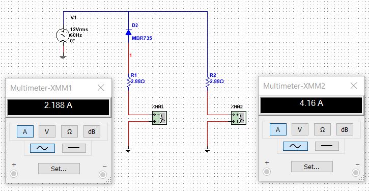
The circuit below shows two branches that have identical resistances but there is a diode in series with it if she performs only other each half cycle. It is a rectifier and theory tells us to wait for the RMS current through resistance to 70.7% of the current flowing through a resistance that does not have the diode in series (for an ideal diode). For R2 below I (R2) = 12/2.88 = 4 .16A and this is properly determined by XMM2 multimeter. The current in the branch of the diode must be 4.16 * 0.707 = 2.94 A but as you can see XMM1 multimeter is far away. I changed the led a virtual model and the current has dropped to 2.14 A...
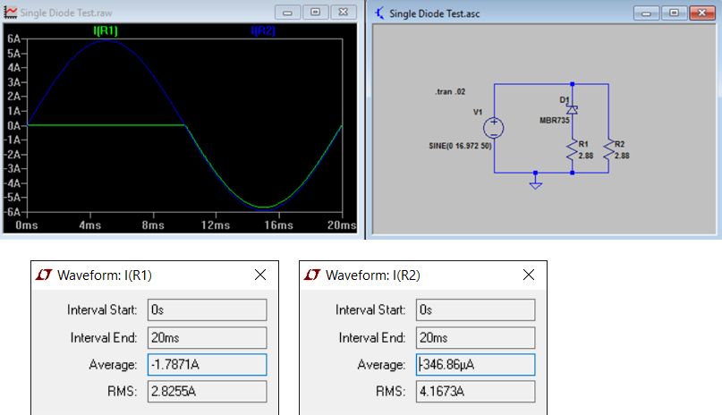
I checked this with the same values of resistance and the diode model using LTSpice and I get the correct results with this program (which allows Fior diode charactersists)...
I have attached two files (Multisim 14 and LTSpice) simulaiton for reference.
So what is happening here?
Hi Myamigo
Thanks for that information, I think that the issue here is with the multimeter and not with the circuit. I used a current probe and got A 2.8 on this line. I enclose a picture showing this.
I think that this may be due to a configuration on this unit or it can also be a CAR, but I need to conduct additional research on this to see if it is a wrongful conduct of Multisim multimeter.
-
Problem of Simulation multivibrator
Hello
I'm trying to simulate a simple multivibrator which I intend to use it to generate a square wave. I use this circuit:

I think that there is no problem with this circuit. Almost everywhere, I found this structure.
In virtually, the tour starts to work because of differences in the elements. Circuit was symmetrical, he started working in the simulation. To work around this problem, I tried to:
* Initailze one of the capacitor
Change of values of transistors Bf
* Take one of them as 2N2222A and other BC107
* Connect a picewise voltage source linear to transmit a transistor turned out (such as the creation of a) of pulse
But none of them worked.
Some of them seems to be working. But the output signal is very different from the square wave.
 (Similar to a square wave noise
  )
)How can I solve this problem?
Thank you very much
Try this in Multisim 10. Your collector resistances are far too high in the resistance. You must also select 'Set zero' for the initial conditions and integration "Gear" in the options analysis. You can add your own PB and LED.
-
How to set up a "dummy" or "virtual" port
Hi, I'm relatively new to Labview programming. I work with the NI USB-6212. I was wondering if it is possible to create a "dummy" or "virtual" port, so I can finally create a port for example line output. port0/line16. Basically I want some bits to go to this line and the "status quo".
Any suggestion would be appreciated.
Thank you
VK
There are several ways to address the issue and how you will use this 'virtual' Port is one of the choice between the methods.
The easiest way is to create a USB-6212 simulation:
Interfaces and select Max devices
Right click > create new > DAQmx simulated device or modular instrument
Expand + M series: DAQ and select NI USB 6212.
You'll be able to create scales channels etc. that are appropriate for a tasks OR USB 6212 assistant DAQmx will treat it as if it was true, and you can try the task and, LabVIEW code call a task on a simulated device will work just fine.
The down side is when you actually get material its often difficult to retarget the tasks for using the real device (no option to send the task... no option to replace the device with...) Do not hesitate at the idea of Kudos. If you need to change the task or swap device names and which is not infallible.
Another option that I use for my development (and, I code by intention... very rarely have any material or simulated in my cube)
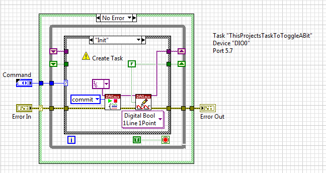
must care not the configuration of the task until I integrate with hardware. Allows to set the example that I have in my current project:
With the exception of the name of the task that this exact code is part of the project I opened today. This AE wraps completely all I want to do with this task. Now, I have the code to fall in my application and can create the easilly task on the target computer. Notice of Here.vi? I'll just go through the hierarchy of the project and find all instances. Create the task and TEST IT on the live system. When all instances of here.vi went my code is error free and integrated with the hardware running.
[edit] it is what happens with a break in three hours while you answer. Tim beats you to it
-
set up a placeholder or virtual DAQmx SCXI task?
is it possible to implement a task DAQmx SCXI without having any SCXI hardware? I don't have access to the material and I was wondering if I could create a "virtual task' for my SCXI program before gettting the material?
Thank you!
Yes. Go to measure Automation Explorer. Devices and Interfaces, do a right click, create new ones... You can then select Virtual Instrument or NOR-DAQmx simulated device.
-
Trace of the end effector of a manipulator Robot in Simulator 3D display
Hi all
I am currently working on a project to control robot on LabVIEW Robotics Module 2013.
In project, I need to show 3D track of the Effector(or an arbitrary point of the last link) in the display of the Simulator.
So so we can easily see the error of monitoring (the diffrerance between the desired trajectory and actual path) on the façade of the Simulator.
I also added a picture of my primitive system to clarify what I needed.
Thank you.
Your photo, it seems that you already have a 3D scene called Simulator display. Is this VI an example that was provided to you? Or have you written this VI?
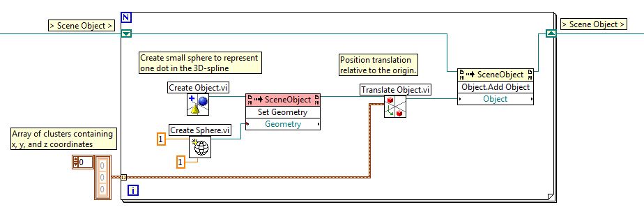
This isn't something I've done before, but assuming that the item titled display Simulator is a 3D scene or a 3D image, you could follow the path of the Effector keeping the Effector 3D locations in a wide range of groups, each with an x, y and z location. 3D scenes/images are used to represent physical objects in a virtual environment, so each location to which you want to trace would become an object. Below is an excerpt where I created a for loop that will create small spheres for each point that is stored in an array of clusters. These spheres are created, moved to the right and then added to the existing 3D scene location.
Your application may be different from what I proposed, but you should start by looking at the example of solar system set out below. This example shows how objects are created, added to scenes and interacts with.
Community: solar system with 3D picture control
-
Hello
My question should be simple enough, but I have not found the answer.
I have a NOR-6509 card and it should be possible, according to the different tutorial nor helper I've read, to simulate the device using MAX, without being connected to my laptop. The thing that would be very useful to develop portable applications c# on my computer when traveling away from the office.
"Now with NOR-DAQmx 7.4 or higher, using simulated devices, you can develop, run, and troubleshoot data acquisition applications without going through the applicable material installed [...] A simulated NEITHER-DAQmx device is a replica of a device created by using the option OR-DAQmx Device simulated in the menu create new from MAX to a function or program without equipment. A device OR-DAQmx simulated behavior similar to a real device. Its driver is loaded, and use programs are fully verified... »
The fact is that I can't do work at the same time, my request - for example, the application of WriteDigPort.exe provided with examples of dotnet 2.0 - and a device of NOR-6509 simulated by a task generated to simulate an output port Dev1/port 0 for example. I have a conflict error.
I don't really see not how to simply check that my request goes to the value '1', for example, every bit of my virtual Dev1/port port 0 MAX and seeing the lights 'virtual '?
Ditto for reading: how e chech with a simultaed device that my request is properly read a port that I set to a specific value?
Thanks much for the reply!
Hello
You can read output simulated. The simulated device aims to offer the possibility to start the program without hardware; also with a simulation device, you can check if the syntax of your program is correct and check if the data you write meets the specifications for your motherboard.
You might find some useful information here:
http://zone.NI.com/DevZone/CDA/tut/p/ID/3698#toc3
Kind regards
-
Hello!
I'm working on a LabVIEW code that uses 5 cards OR (6503,6023,6023,6503,6704). I want to simulate these cards. So I created or daqmx simulated maps. When I run the labview program, I get the error-10401 when I try to use DIOconfig.vi. For more information, I use the traditional daq 7.4.2 driver.
Is it possible to call virtual devices?
Thank you.
Thanks for your response! I have another question. I work with hardware daq - mx. Is it possible to write digital ouptuts and then play just using Labview?
I work with LabVIEW 8.2. First, I create a channel and start a task. Then I execute a loop in which I write and read continuously the same port. But I never see this change...

Maybe you are looking for
-
My mouse not to recognize the links or display behaviors of mouse on the top of a Web page. Why?
My mouse is no longer active on the upper sections of any of the Web pages. Hyperlinks are not recognized, mouseover behaviors do not occur and even the scroll bar will not work as long as I have the page up to a certain point and then drag it to the
-
Hello I would like to add a wireless card to my P2800, Win 2000 family Edition. I decided to go through Netgear PC Card wireless 32-bit CardBus Dual Band WAG511 - 108 MB/sec. What do you think? Do I have a problem with it on my pc? Thanks a lot for y
-
Satellite L350-problems with msn
Is anyone having problems with their msn on this computer cos my guard disconnecting me everytime I turn on my webcam?
-
Hello! I have an application that runs on an RT target that must carry out periodic checks on the devices should be plugged on the target subnet. It is possible to perform a ping to an RT target? Thanks in advance for any suggestion, Marco
-
Issue of the user of LabVIEW interface
Hi guys: I have two question about LV user interface design: Referring to the generation of the LV application: 1 How do I hide the runing mode menu bar 2 How do I change the title, I mean, usually the title of the application window is "xxx.vi", I c