wave sinusoidal mesuare
Plese help me!
I'm reading the value of the RMS of a sine wave input Myrio (AI0 and AI1 - Conector C), but I can't. I need only read this value and convert it to power at the end of my Masters. I do the integration of a Flight Simulator (X-plane) with Myrio and a hydraulic platform. Follow my code.
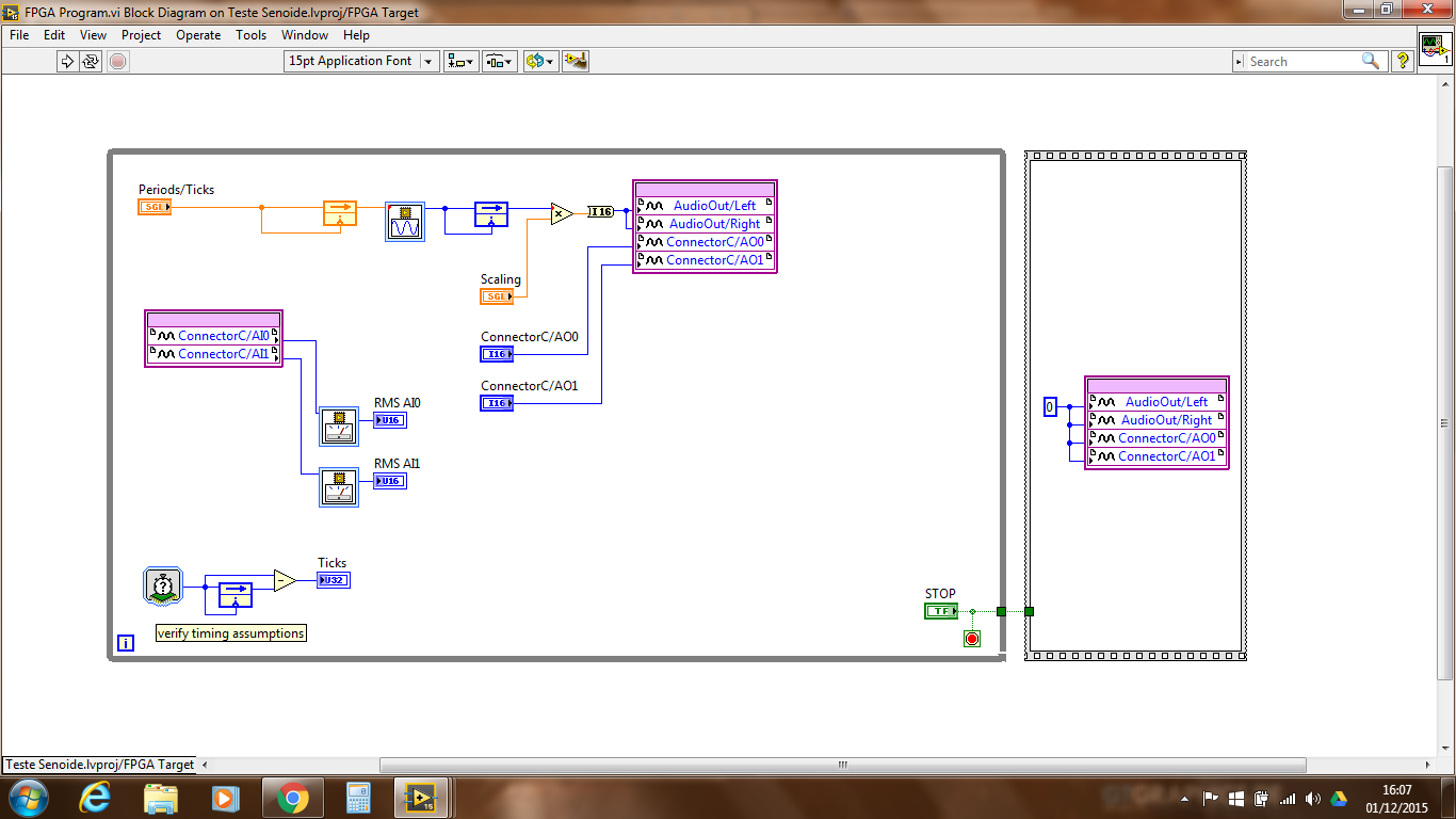
in order to use the molding based RMS, you must define the RMS function parameters to match your use of sample time case rate and measure to coincide with a whole number of periodic cycles or set the option "apply the hanning window" on the express VI.
Is that what you underlyuing periodic signal? How often?
Use the timer function to loop to the rhythm of your loop and use this frequency in the configuration of RMS.
calculate the time to an integer number of cycles of your friequency and use it in the configuraiton of RMS.
Remember, you get only one value of RMS measurement by period using the NI RMS function.
very often, we check the FPGA math using the same algorithm with known in labview for high level data sets. Maybe you can try also.
Tags: NI Products
Similar Questions
-
FPGA wave sinusoidal generation discontinuity
Hi all
I have a question about the generation of sinusoidal waveform FPGA: the generated waveform has unknown non-periodic discontinuity. I want to know where it was generated and how to solve it.
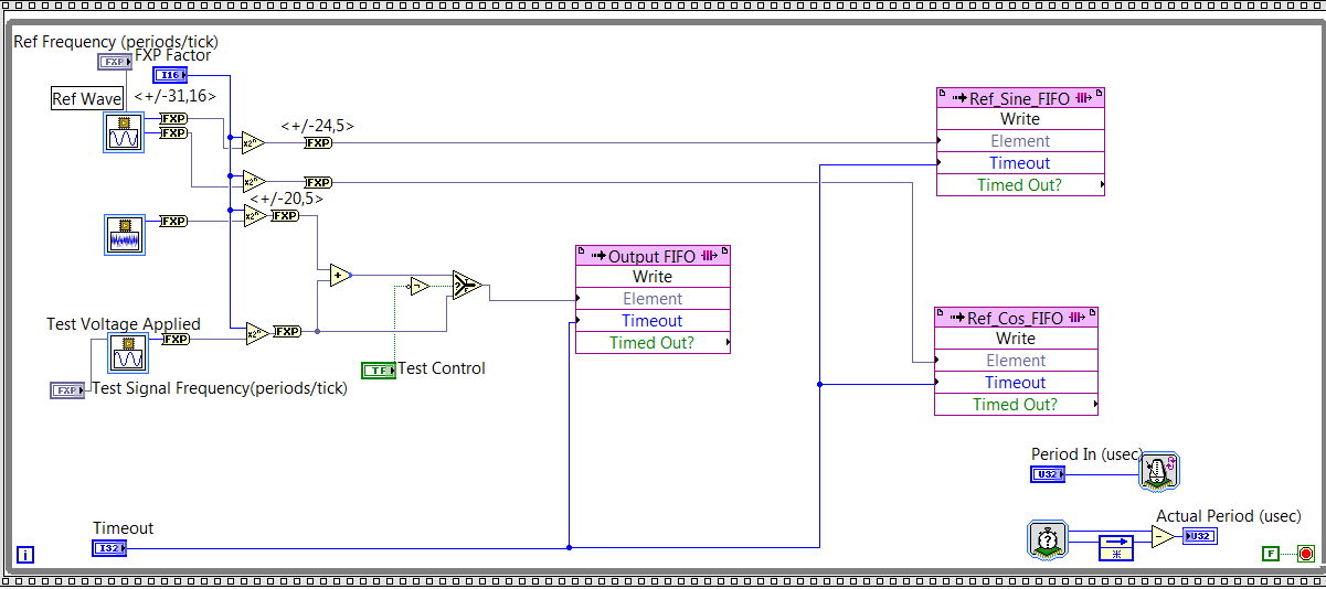
As you can see on my FPGA code below, I generated reference signal - a wave of fishing and a cos wave by using the function of 'generation of the sine wave. Then I write the data to their corresponding FIFO and the sampling rate is controlled by "Period In (usec)" and it is set at 20. Thus, the sampling rate is 50KS/s.
Fig. 1. Code generation of FPGA sin wave
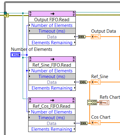
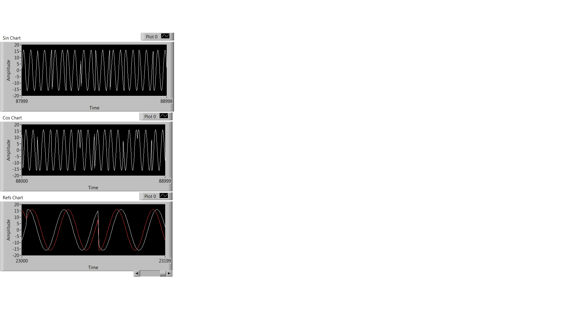
At the level of the RT, I observe the data through the code illustrated in Fig. 2, and what I observe is Fig. 3. Three graphics from top to bottem are: result of the sine, cosine wave result, sin / cos wave shown using the same chart.
Fig. 2 RT level Code
Fig. 3 Sin / Cos waves are the result
Everyone has the same problem ever or any input on what has caused this?
Thank you!
Kind regards
Doris
Hello
Thanks for responding! I think I solved this problem. What's happened is that the execution time for the rest of my code of RT level is longer than the duration for the FIFO to be filled, so the code FPGA that writes data in the FIFO to wait to get code RT to finish. FIFO data are not time continues because of this reason.
Kind regards
Doris
-
Hello world
I tried to generate a signal in the FPGA (with determined amplitude, frequency...) and draw using graphic waveform (also in the FPGA part), but when I put work continually, I get a signal of amplitude 0 during all the time. What's not?
Thank you!
You cannot use the chart on the FPGA. If you want to view the data, it must be done by the host.
The FPGA code is compiled into a bitfile without controls. The controls on the main VI represent the interface of the host and does not (really) to visualize the behavior of the runtime.
It may be useful
Christian
-
Audio spectrum Center wave + more round wave
Hi, first time poster
I'm looking to create a wave of an audio file of a voice and it must look like the clip of Arctic Monkeys (I want to Know?)
The shape of my waves is too strong at the moment and I would like to know if it is possible to focus the highest point of the wave, whenever something is said in the audio clip?
The shape of my waves is too strong
audio waveform has a few design limitations. You can increase the display samples, but it won't be like the clip
I would like to know if it is possible to focus the highest point of the wave, whenever something is said in the audio clip?
You can conform the highest point of the wave of other values via a linear expression. Maybe this will help: Re: Logo bouncing in sync with music
the clip: as you can see the line is very symmetrical and beautiful. Obviously, this is not related to the waveform of the real sound, but a representation which was made manually to keep the aesthetics of the line. If you want to look the same as the clip, here are the different suggestions. digging around for some more information it has been suggested that this type of wave sinusoidal animation was done in software called 3d Maya: https://www.reddit.com/r/animation/comments/350717/looking_for_tutorials_on_how_to_make_th e_audio /
You can get close to this type of look by using the wave effect on a path.

There are still some problems. the line is not this name vertically, it shrinks down. not the same effect.
Another is to try adding a zig zag shape effect - now the line is fine, but the line does not similarly decaying distort. It takes a work more

There is also the possibility that this was done manually through to manipulate a form of path suddenly and using transformations to scale it symmetrically. It's the clip

It could also perhaps be handled more easily through a script or a set of expressions specifically written for this type of wave decaying sinusoidal animation.
-
How to continually take and record waveforms with neither 5102
a machine generates waves sinusoidal time randomly. I want to permanently take and record waveforms in 10s by NI 5102.
How to do?
Thank you very much!!
Thanks for the review! but this isn't a supported NEITHER.
I record signals by this method.
and the promble news is that different sampling frequency, the different wavelength. for example, when I put the sampling frequency is 4 k, the wavelength is 12 seconds if the sampling frequency is 10 k, the wavelength is 8 seconds the signal under test 1 k, the time constant is 10000.
now, I save waveform to 10 sec. What is the best relationship between sampling frequency and the time constant?
-
How to set the simulated on material values simulated?
I simulate the material using the Software NI MAX.
I would like to access the material simulated using the interface in ANSI C.
But I want to get the values.How it is possible to adjust the simulated values?
You can not. The only value of simulation is the wave sinusoidal, as explained in the help.
-
Align the two signals and measure the Phase Shift
Hello
I do an experiment in which I use the NI USB-6221 DAQ card. The jury is able to make 250 k samples/second. I want to measure two voltages in a circuit and find the phase shift between them at frequencies between 1 and 10000. First I ouputted a wave sinusoidal frequency variable through the Commission and applied to a test circuit. Then I used the Board to measure the two tensions consecutively (thus reducing the maximum sampling frequency at 125 k). I used the signals align VI and measured the two phases and then calculates the phase shift (VI attached in Phase 1). It worked well for the test circuit I built in which the phase shift went way logarithmique.20 degrees ~84.5 degrees and then stabilized. At frequencies above 5 000 Hz phase shift must have remained constant, but it varies more or less 1 degree. When the phase shift is 84.5 degrees, present a degree of variability is not particularly explicit. When I asked my program on the circuit that I really wanted to measure, the phase shift went from-. 5 degrees up to about 1.2 degrees. The change in the values of phase shift at high frequencies (> 3000) was environ.2 degrees. Given the small phase shift, this variation is unacceptable. Now I tried to use a sequence to each blood individually (increase the maximum sampling frequency to 250 k) and then align the two signals and measure the phase of each shift. When I use align it and re - sample Express VI to realign the two signals, I get the message "error 20333 analysis: cannot align two waveforms with dt even if their samples are not clocked in phase." Is it possible to align two signals I describe here? I enclose the new VI as Phase 2
Matthew,
I think I have an idea for at least part of the problem.
I took your program data and deleted stuff DAQ. I have converted the Signal on the chart control and looked then what was going on with the signal analysis.
The output of the Waveforms.vi line has two waveforms, like the entry. However, arrays of Y in the two waveforms are empty! It does not generate an error. After some head scratching, reading the help files and try things out, that's what I think is happening: the time t0 two input signals are 1,031 seconds apart. Since the wavefoms contains 1,000 seconds of data, there is no overlap and may not align them.
I changed the t0 on two waveforms are the same, and it lines up. The number of items in the tables is reduced by one. Then I increased the t0 of 0.1 seconds on the first element. The output had both greater than the entry by dt t0 t0 and the size of the arrays was 224998. Reversing the t0 two elements shifts the phase in the opposite direction.
What that tells me, is that you can not reliably align two waveforms which do not overlap.
I suggest that you go to 2-channel data acquisition and that it accept the reduced sample rate. You won't get the resolution you want, but you should be able to tell if something important happens.
You may be able to improve the equivalent resolution by taking multiple steps with a slight phase shift. This is similar to the way that old oscilloscopes of sampling (analog) worked. Take a series of measures with the signal you are currently using. The make enough average to minimize changes due to noise. Then pass the phase of the signal of excitement to an amount that is smaller than the resolution of phase of sampling rate and repeat the measurements. Recall that I calculated that for a 5 kHz signal sampled at 125kHz, you get a sample every 14.4 degrees. If shift you the phase of 1 degree (to the point/mathematical simulation), you get a different set of samples for excitement. They are always separated by 14.4 degrees. Take another series of measures. Transfer phase another degree and repeat. As long as your sampling clocks are stable enough so that frequency does not drift significantly (and it shouldn't with your equipment), you should be able to get near resolution of what you need. The trade-off is that you need to perform more measurements and may need to keep track of the phase shifts between the various measures.
Lynn
-
Why labview programmers use 10.1 the default frequency instead of a same 10.0 Hz?
It was an issue that was raised during the lab class and no one has an answer for. Any ideas?
I call it the wagon wheel effect.
In the old westerns, whenever a wagon with a Ferris wheel to rays rode by the camera, sometimes the wheel would look like it rolls slowly forward, sometimes slowly propagated backwards, sometimes it would look as if it was stopped.
It is a function of the frame rate of the camera over the period of the cycle of the spokes of the wheel. If we spoke (or more) offers exactly the right distance between a frame of the movie and the next, it would look like the wheel had not moved at all. If he moved a little further than the distance from rotation of we talked, it would look like it rolls slowly forward. If the cart is a little slower, then it would move only less than the distance of a spoke and he would look like the wheel rolls backward.
Same thing with having a periodic waveform (every bump of the sine wave is a spoke of the wheel) and a number of acquisition of samples and data rate equal to a whole number of this period (essentially the frame rate of the camera.) Wagon wheel always rolls forward. The sine wave is still oscillating. But according to the rate of acquisition compared to the wave sinusoidal frequency gives a different appearance to the appearance of this sine wave on the chart.
Experiment and give it a 9.9 Hz sinusoid, you will see that it seems to move backward.
So I think (and this is only a guess) is that whoever designed the express VI gave it a default value of 10.1 Hz to visually simulate on the graph of the sine wave motion.
It doesn't really matter what they chose by default as it is to you that the programmer LabVIEW to change this default setting (whether in the express VI or the wiring in a value) to something that makes sense for your application.
-
generation of sinusoidal wave with smu
Is it possible to generate, for example, one 3 a 50 Hz sine wave with SMU 4138 or 4139?
THX
The DCPower API provides no screws to use blocks of power or SME like FGENs. However, it is possible to program the jury at the exit of the standard functions by translating the desired frequency and amplitude to a sequence of continuous output with delays of source is defined so that the output function the user selects is output on the terminals of the device.
The attached program allows you to use a NI 414 x, NI 4135/4136/4137/4138/4139 as a FGEN. As it is, the program is limited to a maximum output frequency of 5 kHz.
I have attached a version of the code for the current output and a version for output voltage waveforms.
-
Problem of analog sinusoidal input USB-6009
Hello
I am a newbie to Labview. I'm using Labview 2009 and USB-6009. I tried to use USB-6009 to display the input sinewave of function generator signal. First of all, the perfect sinusoidal looking at the frequency of 1 kHz, but when I changed the frequency of 10 kHz, the sinusoid turned into a triangle wave. When I test the input signal, I put the 48 kHz sampling and Terminal configuration is CSR. Is there a problem with USB-6009?
You really need to spend some time to study sampling and Nyquist theorem-not LabVIEW. To faithfully reproduce the shape of the sine wave, you must go to a sampling rate 10 times higher than your input frequency. With the 6009, i.e. limit the entry less than 5 kHz.
-
generate a square on the analog output wave
I use a PXI-6229 DAQ card and I need to generate a square on ao0 wave. I'm programming in c# and have found an example of the expedition, which generates a sine wave. I need to be able to modify the function generator that was provided with the example of the expedition to produce a square wave 7.2 kHz with duty cycle of 50% and 2 v peak-to-peak. I enclose the code generator to function.
Thank you
After a lot of trial and error and adapt the example to generate a sinusoidal signal, I have the solution to generate a square signal of analog output. I enclose the code.
-
Measurement of deformation of the sine wave
Hi people.
I'm trying to measure the deformation of the signal coming from a range. Its a sine wave typical that distorts the increase of entry (see attachments). I was initially just to subtract a known since the signal signal to give the difference. The fault point by point is great for this. I also try to figure out the slope over time and rapid changes of the slope would indicate the point. However, point-by-point calculation of the slope gives too much error. Is it possible to generate accurate slopes or y at - it a function that determines if a signal is not sinusoidal?
Thank you
Select this option.
For a quick visual check, you can use vi tone detection and the export of the residual signal, maybe the effective value of the residues is a nice value (THDN)
Measures of deformation of a periodic signal (in general) often made in the frequency domain and called harmonic distortion. Also, there are screws that can already do it for you. (SINAD). The level of DHT is usually used. See signal processing - wfrm measure
Your traces resemble a calibration of accelerometer ball steel 1 g for me.

-
[FPGA] Problem with the sinusoidal signal generator
Hello!
At first I want to apologize for my English is not my mother tongue.
Hardware and software I use is:
LabVIEW 8.5
NEITHER RIO 2.4.1
NEITHER cRIO-9014 (controller in time real CompactRIO)
NEITHER cRIO-9104 (chassis and FPGA)
NEITHER 9264 (16 channels, +-10V, 16-bit voltage analogue output Module)
I made a very simple FPGA VI: a while loop, generator of sinusoidal signal and a FPGA of e/s node in the loop. I've specified the Gnerator settings by following the path:
Frequency = 50 Hz
Amplitude = 1
Phase shift = 0.00
Size of the table look-up = 1024
= 16-bit amplitude resolutionFPGA clock frequency (40 MHz)
But the wave of "sine" I got is not what I wanted to get. First of all, its amplitude is 1 V. shouldn't it be coded on 16 bits? If I wanted to get 1V I should have specified Amplitude as a 3277. In addition, 'sine' is not very detailed, it's look like "steps", as many samples vere missing. What I did wrong? I checked the samples and tutorials, I did everything the same way. A I forgot something or not has not specify other parameters?
Thanks a lot for your help!
OK, I solved a problem. It's embarrassing to admit, but maybe this will help someone else
 I blame my inexperience
The main solution to the problem was changing calibration of calibrated RAW Mode. After that, everythoing works as expected. I had a problem with a sample because I was using a multiplier to control the generated sine wave amplitude. But... She was set to 1 in the sinusoidal signal generator. That was the reason for waveform Gradin. Please, don't laugh too much

In any case, thank you for an answer! It is now resolved
-
How to take a derivative of a sine wave?
I know this is probably very simple and I'm sure that I'm doing something stupid, but please could someone help me... I'm just trying to draw the derivative of a sine wave on the same graph as the original sine wave. There seems to be working (it shows a cosine wave), but the magnitude is far away. Please could someone just point to me why the amplitude is off... the original sine wave going between 1 and -1, but the derivative is between 60 and -60
Just speculating, but...
- The derivative of a sinusoid of 10 Hz should have an amplitude of ±60 remarks (2 * pi * 10).
- The VI of sinusoidal waveform has a default frequency of 10 Hz.
Coincidence?
Best regards
-
FPGA square wave generator diverts loop calendar
Description of the problem:
I have a simple while loop with a structure of matter inside. In one case, I have the
Generator FPGA Sinewave sending the data of output to AO0, otherwise, I have
the square wave FPGA sending output to AO0 generator. The sine and square
waves are set to run at 10 kHzI also have a shift register that changes the State of DIO0 each loop through.
In this way, I can look DIO0 on my scope and say how fast the loop runs.When I choose the sine wave generator, the output on AO0 is what I expect. That
is I have a sinusoidal signal at 10 kHz and the loop speed is approximately 1 US. Everything is good.Then I move to the square wave. I get a signal square 10 kHz, which is good. But
My loop speed was slowed down to 50 US (it follows the square wave
exactly) is: once the loop defines the FS square wave and the
the next time through the loop, it defines the square wave to-FS.My problem is that when I generate a square wave, I expect the speed of loop
to stay fast he does it for the sine wave. You can see what my loop speed
slows to 50 (a square wave of 10 kHz) and then all my calculations that must
go in parallel with the square wave will also be slowed.Please help me with my understanding of the use of the square wave FPGA sub - VI
Thank you
RichSoftware of NEITHER: LabVIEW FPGA Module version 2013 SP1
OR hardware: USB-7855R R Series deviceIf you dig into the express VI, it will loop an SSTL until there is a change in value. The sine wave has no need to do so because the value changes constantly.
If you can, I recommend doing your loop a SSTL and configure the express screw accordingly. This will work as long as the rest of your code in the loop can be run in a single clock cycle.


Maybe you are looking for
-
Satellite M30X-165: new HARD drive does not work
Hi, I want to replace the old hard drive, HITACHI 80 GB in my Satellite M30X 165. I bought SEAGATE Momentus 5400.3 120GB but it seems that it may not be recognized by the BIOS. Anyone know what to do or what types of discs can be used in this noteboo
-
Satellite P200D Memory Upgrade
If I buy the Toshiba Ginga USB 16 GB stick it to increase the memory on my laptop I have spin short so that wouldn't be a good this what else I can do, you can propably guess I don't know anything about the technical side of pc
-
I have a Y480 and I would like to add an mSATA SSD. According to the 128 GB of Crucial m4 mSATA reader is not compatible with the Y480: http://www.crucial.com/store/partspecs.aspx?IModule=CT128M4SSD3 I also watched the 80 GB drive mSATA Intel: http:/
-
Configure the session error # BFFF800B
I have a camera of Dalsa CR-GM00-H6400 model. It's a GigE camera. I have configured and used other Dalsa cameras on this system, but this camera gives me a session configuration error as soon as I click on it. Dalsa Viewer works very well. The ca
-
Several producers an consumers
Hello, I am developing an application where they are drawn at different speeds and different processes, but I want to store it in a file, to store this data I can, if I have several producers and a consumer?