Wave sinusoidal fpga
Hello world
I tried to generate a signal in the FPGA (with determined amplitude, frequency...) and draw using graphic waveform (also in the FPGA part), but when I put work continually, I get a signal of amplitude 0 during all the time. What's not?
Thank you!
You cannot use the chart on the FPGA. If you want to view the data, it must be done by the host.
The FPGA code is compiled into a bitfile without controls. The controls on the main VI represent the interface of the host and does not (really) to visualize the behavior of the runtime.
It may be useful
Christian
Tags: NI Software
Similar Questions
-
FPGA wave sinusoidal generation discontinuity
Hi all
I have a question about the generation of sinusoidal waveform FPGA: the generated waveform has unknown non-periodic discontinuity. I want to know where it was generated and how to solve it.
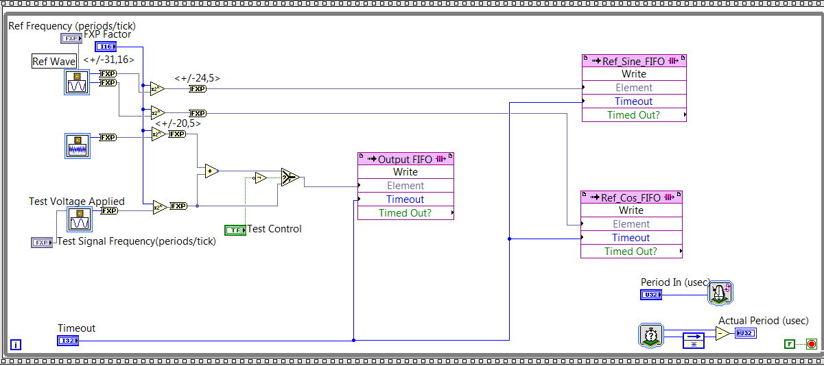
As you can see on my FPGA code below, I generated reference signal - a wave of fishing and a cos wave by using the function of 'generation of the sine wave. Then I write the data to their corresponding FIFO and the sampling rate is controlled by "Period In (usec)" and it is set at 20. Thus, the sampling rate is 50KS/s.
Fig. 1. Code generation of FPGA sin wave
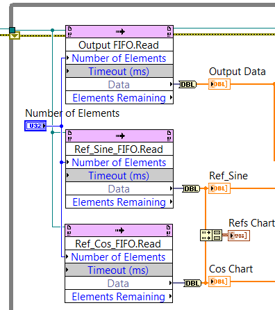
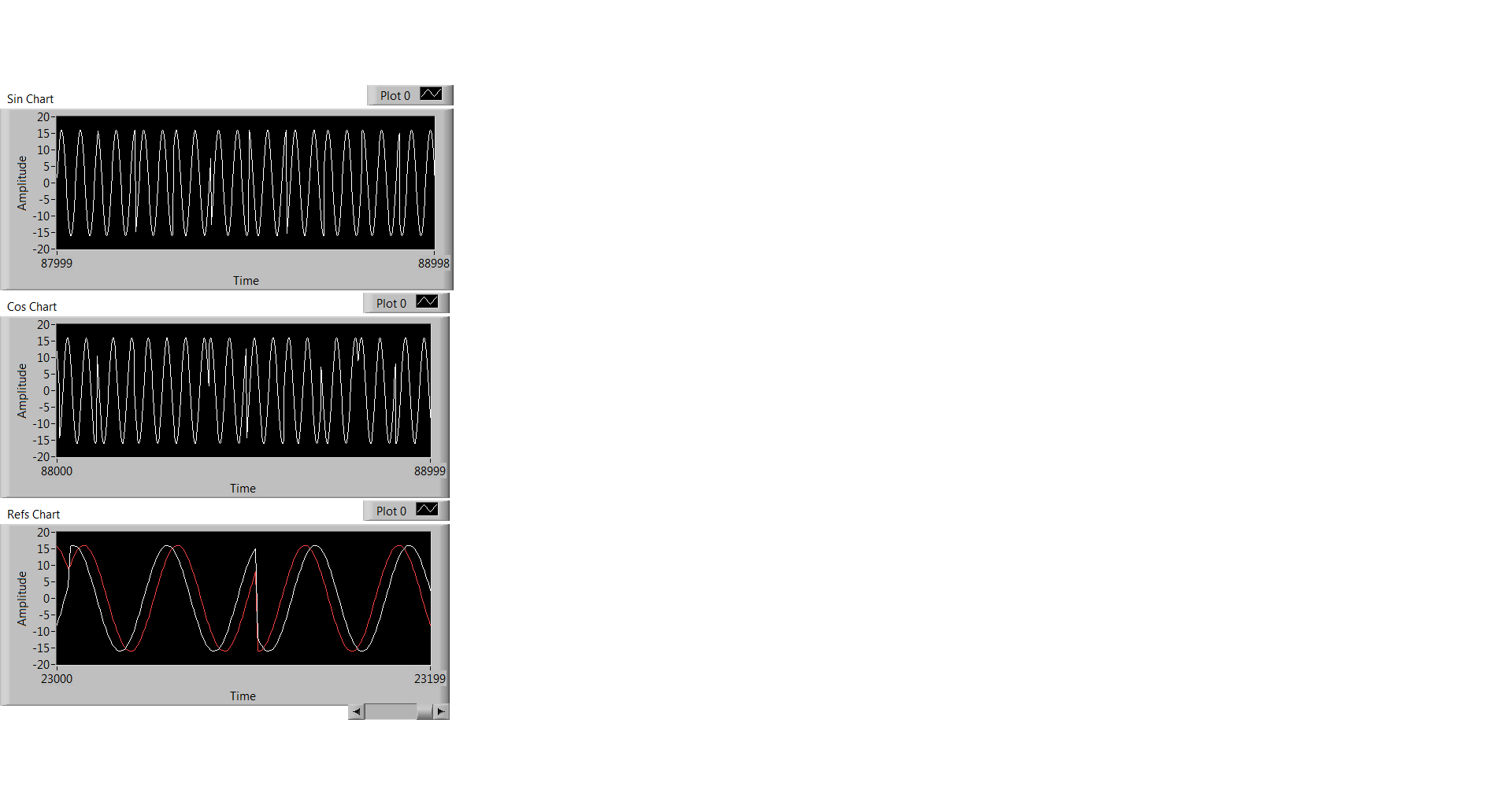
At the level of the RT, I observe the data through the code illustrated in Fig. 2, and what I observe is Fig. 3. Three graphics from top to bottem are: result of the sine, cosine wave result, sin / cos wave shown using the same chart.
Fig. 2 RT level Code
Fig. 3 Sin / Cos waves are the result
Everyone has the same problem ever or any input on what has caused this?
Thank you!
Kind regards
Doris
Hello
Thanks for responding! I think I solved this problem. What's happened is that the execution time for the rest of my code of RT level is longer than the duration for the FIFO to be filled, so the code FPGA that writes data in the FIFO to wait to get code RT to finish. FIFO data are not time continues because of this reason.
Kind regards
Doris
-
Plese help me!
I'm reading the value of the RMS of a sine wave input Myrio (AI0 and AI1 - Conector C), but I can't. I need only read this value and convert it to power at the end of my Masters. I do the integration of a Flight Simulator (X-plane) with Myrio and a hydraulic platform. Follow my code.
in order to use the molding based RMS, you must define the RMS function parameters to match your use of sample time case rate and measure to coincide with a whole number of periodic cycles or set the option "apply the hanning window" on the express VI.
Is that what you underlyuing periodic signal? How often?
Use the timer function to loop to the rhythm of your loop and use this frequency in the configuration of RMS.
calculate the time to an integer number of cycles of your friequency and use it in the configuraiton of RMS.
Remember, you get only one value of RMS measurement by period using the NI RMS function.
very often, we check the FPGA math using the same algorithm with known in labview for high level data sets. Maybe you can try also.
-
Audio spectrum Center wave + more round wave
Hi, first time poster
I'm looking to create a wave of an audio file of a voice and it must look like the clip of Arctic Monkeys (I want to Know?)
The shape of my waves is too strong at the moment and I would like to know if it is possible to focus the highest point of the wave, whenever something is said in the audio clip?
The shape of my waves is too strong
audio waveform has a few design limitations. You can increase the display samples, but it won't be like the clip
I would like to know if it is possible to focus the highest point of the wave, whenever something is said in the audio clip?
You can conform the highest point of the wave of other values via a linear expression. Maybe this will help: Re: Logo bouncing in sync with music
the clip: as you can see the line is very symmetrical and beautiful. Obviously, this is not related to the waveform of the real sound, but a representation which was made manually to keep the aesthetics of the line. If you want to look the same as the clip, here are the different suggestions. digging around for some more information it has been suggested that this type of wave sinusoidal animation was done in software called 3d Maya: https://www.reddit.com/r/animation/comments/350717/looking_for_tutorials_on_how_to_make_th e_audio /
You can get close to this type of look by using the wave effect on a path.

There are still some problems. the line is not this name vertically, it shrinks down. not the same effect.
Another is to try adding a zig zag shape effect - now the line is fine, but the line does not similarly decaying distort. It takes a work more

There is also the possibility that this was done manually through to manipulate a form of path suddenly and using transformations to scale it symmetrically. It's the clip

It could also perhaps be handled more easily through a script or a set of expressions specifically written for this type of wave decaying sinusoidal animation.
-
How to continually take and record waveforms with neither 5102
a machine generates waves sinusoidal time randomly. I want to permanently take and record waveforms in 10s by NI 5102.
How to do?
Thank you very much!!
Thanks for the review! but this isn't a supported NEITHER.
I record signals by this method.
and the promble news is that different sampling frequency, the different wavelength. for example, when I put the sampling frequency is 4 k, the wavelength is 12 seconds if the sampling frequency is 10 k, the wavelength is 8 seconds the signal under test 1 k, the time constant is 10000.
now, I save waveform to 10 sec. What is the best relationship between sampling frequency and the time constant?
-
How to set the simulated on material values simulated?
I simulate the material using the Software NI MAX.
I would like to access the material simulated using the interface in ANSI C.
But I want to get the values.How it is possible to adjust the simulated values?
You can not. The only value of simulation is the wave sinusoidal, as explained in the help.
-
Align the two signals and measure the Phase Shift
Hello
I do an experiment in which I use the NI USB-6221 DAQ card. The jury is able to make 250 k samples/second. I want to measure two voltages in a circuit and find the phase shift between them at frequencies between 1 and 10000. First I ouputted a wave sinusoidal frequency variable through the Commission and applied to a test circuit. Then I used the Board to measure the two tensions consecutively (thus reducing the maximum sampling frequency at 125 k). I used the signals align VI and measured the two phases and then calculates the phase shift (VI attached in Phase 1). It worked well for the test circuit I built in which the phase shift went way logarithmique.20 degrees ~84.5 degrees and then stabilized. At frequencies above 5 000 Hz phase shift must have remained constant, but it varies more or less 1 degree. When the phase shift is 84.5 degrees, present a degree of variability is not particularly explicit. When I asked my program on the circuit that I really wanted to measure, the phase shift went from-. 5 degrees up to about 1.2 degrees. The change in the values of phase shift at high frequencies (> 3000) was environ.2 degrees. Given the small phase shift, this variation is unacceptable. Now I tried to use a sequence to each blood individually (increase the maximum sampling frequency to 250 k) and then align the two signals and measure the phase of each shift. When I use align it and re - sample Express VI to realign the two signals, I get the message "error 20333 analysis: cannot align two waveforms with dt even if their samples are not clocked in phase." Is it possible to align two signals I describe here? I enclose the new VI as Phase 2
Matthew,
I think I have an idea for at least part of the problem.
I took your program data and deleted stuff DAQ. I have converted the Signal on the chart control and looked then what was going on with the signal analysis.
The output of the Waveforms.vi line has two waveforms, like the entry. However, arrays of Y in the two waveforms are empty! It does not generate an error. After some head scratching, reading the help files and try things out, that's what I think is happening: the time t0 two input signals are 1,031 seconds apart. Since the wavefoms contains 1,000 seconds of data, there is no overlap and may not align them.
I changed the t0 on two waveforms are the same, and it lines up. The number of items in the tables is reduced by one. Then I increased the t0 of 0.1 seconds on the first element. The output had both greater than the entry by dt t0 t0 and the size of the arrays was 224998. Reversing the t0 two elements shifts the phase in the opposite direction.
What that tells me, is that you can not reliably align two waveforms which do not overlap.
I suggest that you go to 2-channel data acquisition and that it accept the reduced sample rate. You won't get the resolution you want, but you should be able to tell if something important happens.
You may be able to improve the equivalent resolution by taking multiple steps with a slight phase shift. This is similar to the way that old oscilloscopes of sampling (analog) worked. Take a series of measures with the signal you are currently using. The make enough average to minimize changes due to noise. Then pass the phase of the signal of excitement to an amount that is smaller than the resolution of phase of sampling rate and repeat the measurements. Recall that I calculated that for a 5 kHz signal sampled at 125kHz, you get a sample every 14.4 degrees. If shift you the phase of 1 degree (to the point/mathematical simulation), you get a different set of samples for excitement. They are always separated by 14.4 degrees. Take another series of measures. Transfer phase another degree and repeat. As long as your sampling clocks are stable enough so that frequency does not drift significantly (and it shouldn't with your equipment), you should be able to get near resolution of what you need. The trade-off is that you need to perform more measurements and may need to keep track of the phase shifts between the various measures.
Lynn
-
Why labview programmers use 10.1 the default frequency instead of a same 10.0 Hz?
It was an issue that was raised during the lab class and no one has an answer for. Any ideas?
I call it the wagon wheel effect.
In the old westerns, whenever a wagon with a Ferris wheel to rays rode by the camera, sometimes the wheel would look like it rolls slowly forward, sometimes slowly propagated backwards, sometimes it would look as if it was stopped.
It is a function of the frame rate of the camera over the period of the cycle of the spokes of the wheel. If we spoke (or more) offers exactly the right distance between a frame of the movie and the next, it would look like the wheel had not moved at all. If he moved a little further than the distance from rotation of we talked, it would look like it rolls slowly forward. If the cart is a little slower, then it would move only less than the distance of a spoke and he would look like the wheel rolls backward.
Same thing with having a periodic waveform (every bump of the sine wave is a spoke of the wheel) and a number of acquisition of samples and data rate equal to a whole number of this period (essentially the frame rate of the camera.) Wagon wheel always rolls forward. The sine wave is still oscillating. But according to the rate of acquisition compared to the wave sinusoidal frequency gives a different appearance to the appearance of this sine wave on the chart.
Experiment and give it a 9.9 Hz sinusoid, you will see that it seems to move backward.
So I think (and this is only a guess) is that whoever designed the express VI gave it a default value of 10.1 Hz to visually simulate on the graph of the sine wave motion.
It doesn't really matter what they chose by default as it is to you that the programmer LabVIEW to change this default setting (whether in the express VI or the wiring in a value) to something that makes sense for your application.
-
[FPGA] Problem with the sinusoidal signal generator
Hello!
At first I want to apologize for my English is not my mother tongue.
Hardware and software I use is:
LabVIEW 8.5
NEITHER RIO 2.4.1
NEITHER cRIO-9014 (controller in time real CompactRIO)
NEITHER cRIO-9104 (chassis and FPGA)
NEITHER 9264 (16 channels, +-10V, 16-bit voltage analogue output Module)
I made a very simple FPGA VI: a while loop, generator of sinusoidal signal and a FPGA of e/s node in the loop. I've specified the Gnerator settings by following the path:
Frequency = 50 Hz
Amplitude = 1
Phase shift = 0.00
Size of the table look-up = 1024
= 16-bit amplitude resolutionFPGA clock frequency (40 MHz)
But the wave of "sine" I got is not what I wanted to get. First of all, its amplitude is 1 V. shouldn't it be coded on 16 bits? If I wanted to get 1V I should have specified Amplitude as a 3277. In addition, 'sine' is not very detailed, it's look like "steps", as many samples vere missing. What I did wrong? I checked the samples and tutorials, I did everything the same way. A I forgot something or not has not specify other parameters?
Thanks a lot for your help!
OK, I solved a problem. It's embarrassing to admit, but maybe this will help someone else
 I blame my inexperience
The main solution to the problem was changing calibration of calibrated RAW Mode. After that, everythoing works as expected. I had a problem with a sample because I was using a multiplier to control the generated sine wave amplitude. But... She was set to 1 in the sinusoidal signal generator. That was the reason for waveform Gradin. Please, don't laugh too much

In any case, thank you for an answer! It is now resolved
-
FPGA square wave generator diverts loop calendar
Description of the problem:
I have a simple while loop with a structure of matter inside. In one case, I have the
Generator FPGA Sinewave sending the data of output to AO0, otherwise, I have
the square wave FPGA sending output to AO0 generator. The sine and square
waves are set to run at 10 kHzI also have a shift register that changes the State of DIO0 each loop through.
In this way, I can look DIO0 on my scope and say how fast the loop runs.When I choose the sine wave generator, the output on AO0 is what I expect. That
is I have a sinusoidal signal at 10 kHz and the loop speed is approximately 1 US. Everything is good.Then I move to the square wave. I get a signal square 10 kHz, which is good. But
My loop speed was slowed down to 50 US (it follows the square wave
exactly) is: once the loop defines the FS square wave and the
the next time through the loop, it defines the square wave to-FS.My problem is that when I generate a square wave, I expect the speed of loop
to stay fast he does it for the sine wave. You can see what my loop speed
slows to 50 (a square wave of 10 kHz) and then all my calculations that must
go in parallel with the square wave will also be slowed.Please help me with my understanding of the use of the square wave FPGA sub - VI
Thank you
RichSoftware of NEITHER: LabVIEW FPGA Module version 2013 SP1
OR hardware: USB-7855R R Series deviceIf you dig into the express VI, it will loop an SSTL until there is a change in value. The sine wave has no need to do so because the value changes constantly.
If you can, I recommend doing your loop a SSTL and configure the express screw accordingly. This will work as long as the rest of your code in the loop can be run in a single clock cycle.
-
Simulate the sine wave using LabVIEW FPGA with NOR-myRIO and display in real time
Hello
I'm relatively new to LabVIEW FPGA. I am trying to test (and later apply) controllers high speed on myRIO.
At this point, I'm trying to simulate the sine wave from 1 to 10 kHz using Sinewave generator VI express. I also intend to display the sine wave on the time real (RT) using FIFO. However, I had a bit of trouble to understaing various synchronization parameters.
1. how to encode information about the sampling frequency generating sine wave? (The side FPGA vi requires only the frequency of the signal and possibly phase and does not rate update lines)
2. how to estimate the number of items in a FIFO? (that is, the relationship between the rate of updates to loop (RT), the signal frequency, sampling frequency and the number of items in the FIFO)
It would be great if we could share a very simple program (side host and target) that did something similar.
Thank you
MILIN
Milot,
I think the problem is the type of data in your FIFO. Your FIFO is configured to use a data type of I16. The problem is the number, it displays only ever will be-1, 0 or 1. To resolve this problem, you must send the sine wave as a fixed point data and convert it to a double on the side of the RT. This should significantly improve your resolution.
-
FPGA: Change the sinusoidal signal generator
The sine wave in the FPGA palette generator, that's what I need to do
but he can't exit do 'cosine', which is outside of 90 degrees. I need 120
degrees. To avoid discouraging, I opened the façade on the sine wave
Express VI generator that turned into a normal sup - vi. I changed the
a digital constant corresponding to 120 degrees out of phase, and the name was changed
of the output pin.The module will not compile. First mistake was a wire that was a type of variable, the
Fix suggested to check a box for pre-allocating did not work so I made the table
the length constant of 1024 (that is, it is supposed to be). Following error was
that one line of vhdl file was too long (32 k characters for a specification of length 4 k max
characters).Just for grins, I put the original VI Express return with the release of cosine and
It builds correctly.There was a big damper on the modification of the vi. However, I didn't know that
simple conversion to a subvi and the tweak of a constant value would break.Is it possible to get an updated the express vi for this application, or advice on how
changing the text that is there? The compilation breaks mainly online VHDL
length associated with the range of 1024 points.I can roll my own generator of sinus by using some examples, not a big problem but
It will cost you some time. Another option might be to run two generators of sinus
and specify a different phase, but I'm not convinced that over time they
will be exactly synchronized. Change the Express VI is a much better
option.Thanks in advance,
Bill
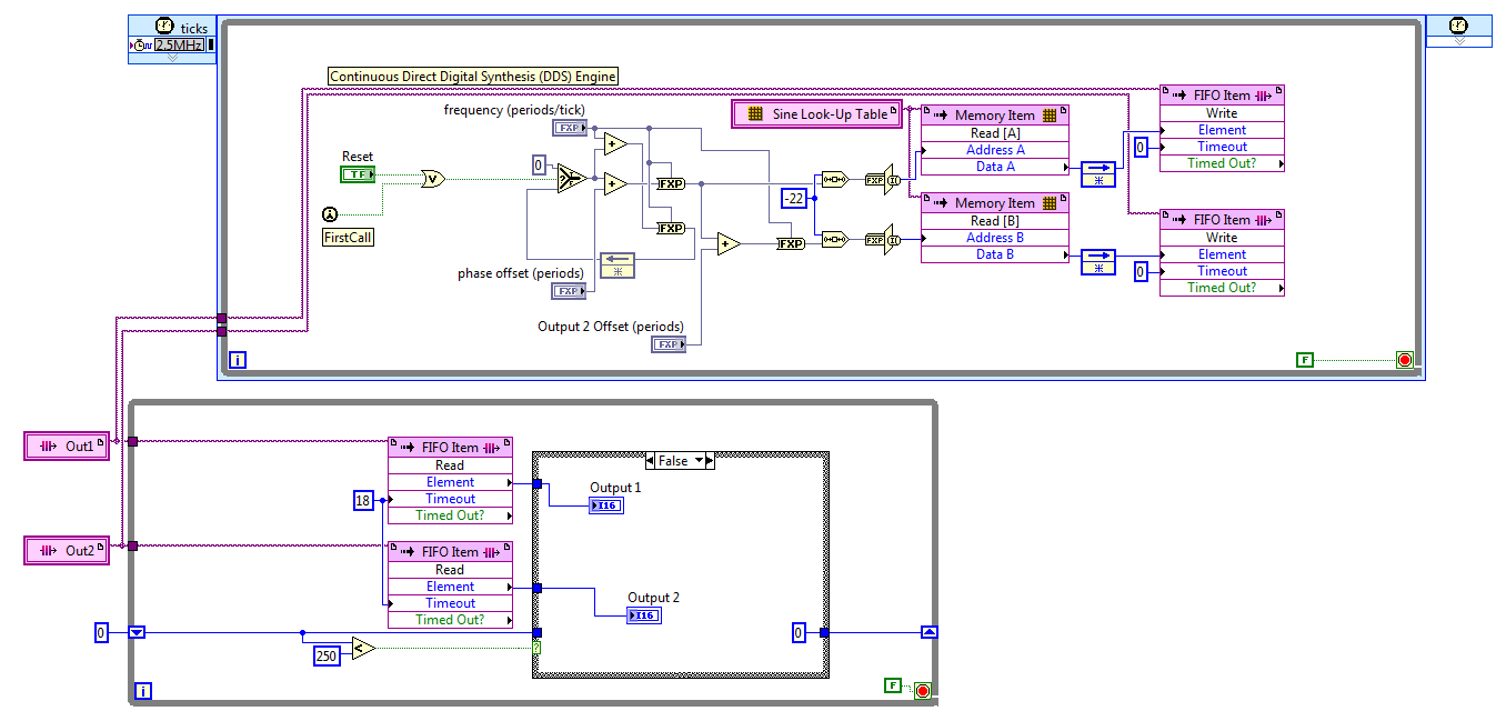
I discovered the hard way that LabVIEW 2011 has no records. After reviewing various options, I settled on the FIFO. The code presented here works well, but it is not save space on the FPGA to the wire using two generators of sinus with a phase difference in hard on one of them. For now, I'll use two sine generators, if this turns out to be unworkable in practice due to the relationship of phase adrift, then I'll look at it again.
The frequency and phase of the compensating controls are fixed point numbers formatted in zero whole bit and a 32-bit word. Bed down while the loop is synchronized with the loop timed by the FIFO, FIFO of 18 ticks timeout is two more than the 2.5 MHz in a loop which is a ditch-16. The IF block in the lower part, while the loop cut update control up to 10 KHz, 60 Hz sines more quickly.
Great experience, thank you for the help.
Kind regards
Bill
-
Generation of sinusoid frequency accurate FPGA
Hello everyone,
I have a myRIO and I want to build a lock in the amplifier. To this effect, I need excite (in fact the driver laser) laser with a certain frequency, in a case 32754 + to 1 Hz. This signal must be a square wave. I need a sine and a cosine with the excact same frequency that I use to turn on the laser. But the sine and cosine do not have to be sent outside the FPGA through a port analog or digital.
To summarize, I have need of a square wave, sine and cosine with excactly the same frequency. Only the square wave is sent through an analog port. (I use the "square wave generation.vi")
This works very well for example 4212 Hz. But 32754Hz can't be represented pretty good by a 40 MHz clock (a lot of jitter). To this effect, I thought to use a Schmitt Trigger.
Finally I come to the point! I use the "generator.vi of sine wave' on the FPGA.
Can I output a sine wave signal with any frequency I want to use this VI, if right of Nyquist is hurt? As this VI uses DDS I think that Yes, can anyone confirm this?
I only ask, because the sine wave will be converted into a square by the schmitt trigger signal and should always have the same frequency that it represents in the FPGA.
Kind regards
Slev1n
Slev1n wrote:
Hey, JLewis,.
1, how can I calculate/derive the resolution?
2, the size of the LUT or also the resolution of the amplitude of the a influence on the resolution of frequency?
1. the resolution only depends on the accumulator and clock rate, e.g. 40 MHz / 2 ^ 32. The rate of the clock increases the resolution of the average frequency of DDS, but will negatively affect the jitter due to the clock period. In your case, it seems that you are more interested in the resolution of frequencies without jitter, which are those for which the clock frequency is an integer multiple of the frequency, for example freq * k = 40 MHz. You can play games with clocks derived from hitting a specific frequency, but in general most of the frequencies will be free of jitter.
2. the other settings do not affect the resolution, but affect the phase noise and/or quantification. For your application, I expect that phase noise is the biggest problem and is affected by the LUT, the interpolation option size and samples/cycle (IE, the rate of the loop). Quantization noise is affected by the output data type and amplitude (otherwise the range). You will get a filtering via the D/A conversion and the Schmitt trigger, so it is difficult to predict how much of a concern these parameters will be for you.
You can see the Xilinx DDS generator (on the pallets of Xilinx IP integration). He has a few more options as the dithering phase and a 48-bit accumulator. On the theory and the effects of various parameters of their documentation is excellent: http://www.xilinx.com/support/documentation/ip_documentation/dds_compiler/v6_0/pg141-dds-compiler.pd...
I hope this helps!
-
FPGA (PXI-7852R) Square Wave DIO
I need to improve the noise to the DIO square pulse pulse width. With my current code (attached .png) I see 25 ~ ns jitter on the front coming down from the impulse (I have the trigger on the rising) with my oscilliscope. This Jig is present even with only a single output square wave (i.e., I delete the other square wave generators).
Any ideas how to improve the fidelity of pulse width?
Thanks in advance!
25 ns is the period of your clock to 40 MHz, the jitter is unavoidable at this clock frequency. The DDS square wave algorithm produces a very precise frequency over time, but cannot control the speed at which it is called to update.
If you set the clock of the loop to a greater frequency of derived clock, you shoot the Jig by the same factor. Right-click on a 40 MHz clock embedded in the project with the FPGA target and choose new clock derived from FPGA. You may need to experiment a bit to see how high you can set the clock frequency without introducing sync in compiling violations; new targets will allow higher clock rates generally. Set up your single cycle timed loop to use the derived clock and don't forget to update your average square configuration with the new clock frequency.
-
generation of sinusoidal wave with smu
Is it possible to generate, for example, one 3 a 50 Hz sine wave with SMU 4138 or 4139?
THX
The DCPower API provides no screws to use blocks of power or SME like FGENs. However, it is possible to program the jury at the exit of the standard functions by translating the desired frequency and amplitude to a sequence of continuous output with delays of source is defined so that the output function the user selects is output on the terminals of the device.
The attached program allows you to use a NI 414 x, NI 4135/4136/4137/4138/4139 as a FGEN. As it is, the program is limited to a maximum output frequency of 5 kHz.
I have attached a version of the code for the current output and a version for output voltage waveforms.


Maybe you are looking for
-
ENVY dv6t-7300 CTO Quad Editio: Envy dv6 IDT sound card does not
Recently, the sound card for computer laptop has had problems. For a month or two I get appears randomly in my audio using several 1/8 "cables to my speakers and headphones. Now my problem is that the card is not to give me audio quality and it seem
-
Satellite L300-1F8 freezes with Win 7 but ok under Win XP
Hello made me this Satellite L300-1F8 as hand down from my sister, and first glance seems he was in working condition.There is no OS on it and I decided to install it with windows 7.It starts up fine on the disc, but after some time on the installati
-
ATI Mobility Radeon HD 5470 (switchable)
Hello ATI Mobility Radeon HD 5470 512 MB and an integrated ATI Mobility Radeon HD4250SINCE I only see ATI Mobility Radeon HD4250 has 4200 sees that the other has a standard vga. recovery after the restoration, the blue screen of death occurs after a
-
peripheral audio Acer Aspire 5517 vista
The audio device driver has disappeared from my computer. How can I reinstall it?
-
Pavilion dm4t Beats Edition: connector Zif keyboard dtm4
I need identify the connector zif for my dmt4 keyboard. I broke the black locking tab and need to buy a replacement connector so I can use the locking tab. Of course, there are different types of connectors of zip.