Why my digital output give 1V instead of 5V?
I have a PCI-6030E. When I look at its digital output to port0/$line0, I see 1V instead of 5V when it is 'high '. He read 0V when 'low '.
Any ideas?
Amit
The only other thing I can think is that you don't have a good connection to DGND during the measurement or the line is maybe configured as an input. If this isn't the case, the card may be faulty.
Tags: NI Hardware
Similar Questions
-
USB-6008 to give the digital output
Hi all
I was wondering anyone at - it base an example of an exercise using USB 6008 to give a digital output of a VI in Labview.
I am very new to the use of the USB 6008 AND Assistant DAQ and so far I've had reading a temperature, next step is I want the USB-6008 to give a + 5v output when the temperature reaches a certain value, I built a Labview 2009 VI for the temperature reading, but now I'm stuck on this piece.
Any help is appreciated! or if there are examples of laboratory exercises that exist that I can perhaps draw.
Hi Marko
Please take a look at the link that has some interesting and intuitive video to use the USB-6008 housing and how to set up the device for several applications in LabVIEW below. Please take a look at the step by step videos and let me know how you go. They are under the tab '"virtual Demos.
-
Fortunately the cRIO merger two time real screws: analog and digital output
Howdy,
I need help with a cRIO code. The purpose of the code is to acquire an analog input from the NI 9234 c series module and be able to send a "signal of pulse" digital camera (first low for some time, t1, then high for some time, t2) from a NI9401. Separately, I wrote the code to perform both tasks. However, when I add the code of RT digital output pulse pulses to analog input RT code, the DMA FIFO overflows because of the way that my digital pulse output code works. Currently, there are two reasons which overflows of the FIFO:
- The digital output code is pending for a while loop (pending "Send Pulse" become a true), the loop I can't empty the buffer FIFO
- The FIFO is not enough, quickly emptied depending on how long the pulse (t1 and t2) times are. The way I keep the pin high or low for a defined period of time is by issuing a sleep command, which blocks the loop I empty the FIFO. (Is there a "best" way to sleep?)
I have attached photos of my codes FPGA and RT. Please give me a suggestion on how to marry my two loops of RT for the use of happy resources! Thank you.
I found a quick way to solve this problem. I moved the timing of the Digital pulse on the FPGA. So whenever I have a Boolean value, the FPGA generates a waveform with the settings I put (a pulse in my case). This works because the FPGA loops run in parallel, I think. That's why, when I run a pending order in the loop of FPGA digital output, it does not prevent the FPGA of analog input loop to run. I have attached a picture of the code.
-
Synchronization of analog and digital output with the external sample clock
Hello
First of all sorry for my English, I will try to explain what I want to do.
I want my PCIe-6321 to send two custom signals (modification sawtooths) on a mirror controller. I would also like to generate output with my card at the beginning of each tooth of saw. Everything must be synchronized with an external k-clock signal of 100 kHz. The idea is that whenever the PCI receives a trigger to external clock, it sends two analog output voltages and when he received 1024 clock ticks it will also send a pic of triggering TTL. What I do is first prepare the map and after that in a loop sending and modifing the output values of the two signals and at the same time send a digital signal Boolean in each arch, so when's done it 1024 iterations of the loop I send an event to the digital port. Attached you can see.
The problem is that I don't know how to synchronize both. Can I use the sample clock just to the analog output? I can use sample for the two outputs clock, or do I need to use the output of the meter? If don't know how to use it here.
If I do nothing else bad/wrong, I would be grateful for feedback.
Thanks in advance,
PabloI don't know how but I find the solution. I'm generating more than a positive value (as I was triggered maybe very fast the oscilloscope has been absent there). If I put the sample clock of digital output to use the sampling/ao/Dev1 clock that it doesn't, but if I put to use the same source as the OD (terminal where my external clock is connected), but the trigger to start the DO to be Dev1/ao/StartTrigger this works. I don't really know why, but it does.
Thank you for your patience and your help. I put here the final code.
-
NI USB-6501 digital output problem
Hello
I use DASYLab v.11 and I'm working on an interface with the NI USB-6501 where I'm putting a digital high on four ports.
With the module "NOR-DAQmx - digital input", I managed to read the digital inputs of the ' NI USB-6501 ".»
It's only the "NOR-DAQmx - digital output" I can't go to work.
Using 'NI MAX' of NOR I have easily can emmit my four LEDs in the way of my High/Low ports.
But not with DASYLab. When you use DASYLab tension on the ports remains unchanged.
Now, I have a switch module, generating 5/0, directly connected to the digital output module, which is assigned to my four output ports for my task.
I also tried with a module of relay between the two without success. I also tried to use 1.5 above instead of 5 without success.
I use the option 'Bus (0/5 supply) for the module "Digital output".
"NI Max", I configured the ports as "active drive.
Any suggestion of what I might be missing?
Thank you
Martin
Hmm, four ports, or four lines?
A port consists of eight lines. Each line can control an LED (ON / OFF ~ 0/5V).
If you have created a task to dig-out to control a port, 5V to this port sending sets all lines of this port to 'high '.
You need to 255 for each line one too high port (at the bit level: 128 + 64 + 32 + 16 + 8 + 4 + 2 + 1).<- eight="">
Or, you can create a dig out tasks to control four lines of a specific port.
Four lanes of the EEG DAQmx DigOut module.
Each of the channels of the modul will feed a single line of the task/device.
Four switches will then turn the lights, or turn off.
Make sure, that the 'bitposition' is the number of correct line (see picture).
-
Hallo,
I use the following system:
- OR PXI-1044 with controller NI PXI-8109
- OR PXI-2564 switch module to turn on the monitor of my test device
- Data acquisition multifunction NI PXI-6259 to measure the signal that responded to the questionnaire jump
The two cards are the same - PXI trigger bus. For both, PXI-2564 and PXI-6259 I use DAQmx to set the reading and writing of the channels.
Now, I want to measure the time between the digital output, my unit turns and the analog input, which measures the response of my system.
I can't do work by myself, please help me!
I thank Ludwig.
Hi Ludwig,.
If you can't give us any VI we have difficulties with to help you.
Because I Donat knowledge how your program is mounted it is not easy to know where you should enter signals.
Here's a question similar to yours:
http://forums.NI.com/T5/LabVIEW/best-way-to-measure-time/TD-p/178704
and 2 external links:
http://www.ehow.com/how_8698983_measure-time-LabVIEW.html
http://objectmix.com/LabVIEW/385152-how-can-i-use-LabVIEW-measure-time-between-analog-pulses.html
-
Hello
I am trying to learn labVIEW DAQ and right now I'm trying to understand how to use NI 9474 with labview. NEITHER 9474 is a device with digital outputs. I am attaching a (badly drawn) diagram of how I have my real wired circuit. For some reason, the voltage at the terminals of the resistance is 9v instead what that either the digital output should be when I put assistant daq for 1 sample on request. When I change to continuous samples daq assistant, it reads 4.6v. So I wonder what am I doing wrong and what should my digital output be?
I've attached my vi file, if someone can you please help me understand how to use NI 9474 with labview?
-
analog sync of input with the onset of the digital output
I'm trying out an analog signal to a file with a specified frequency samples. I also need a digital output to trigger a measurement at a frequency specified on a separate system. The frequency is controlled by the loop exits and timed when the iteration number divided by the period is exactly a whole number.
Both outputs work. The problem is that they are not synchronized. The analog output amounts to about 0.5 ms faster than the digital signal. (I checked with an oscilloscope) They both start in the 1 ms each loop runs for, but I really need them to start at the same instant. What can I do to synchronize? Also, if I'm going in the wrong direction complete, please indicate.
I use a card PCI-6723, which I think someone at some point, said not having a material sample clock. That's why I try to use a timed software loop.
Hi NEA.
You must use the 6723's built-in calendar to accomplish what you want. As the digital output subsystem is only clocked by the software, an appropriate solution should be to use one of the counters to the pulse output.
The attached code should show how. You can use the counter to output a pulse all samples of the AO N task. Material requires the initial delay to have a minimum of 2 ticks, so the meter will be behind the task of the AO by 2 samples in this case. There are different ways to work around this problem if you need (for example write two samples of 0 first).
Best regards
-
clock calendar - digital output
Hi all!
I need timing equipment impliment on a few digital output lines. That's what I have so far:
I didn't get an oscilloscope for her yet, but I'm fairly certain that it works. Please note that in this example, I use a PCI-6115. I have 2 questions:
(1) make what I do look reasonable at a quick glance?
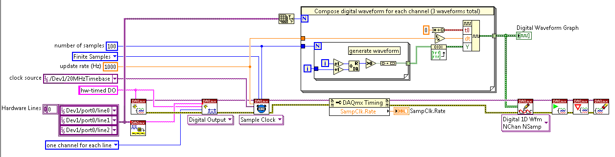
(2) I'm kinda mistified by the entry of clock source to the example of the clock function. The analysis that I read just still confuses me. I understand that the clock is what dictates the sequence of material. I do not understand how to choose the appropriate clock source correctly. More specifically, in the above example, I've only had the program work when I chose "20MHzTimebase". What is c? Why this work?
When I try to select ' Dev1 / / SampleClock ", I get the following error:"attempted to perform a route when the source and destination are the same point."
When I try to select "Dev1/PFI0" or "RTSI0/DEV1", I get a timeout error in the wait_until_done.vi--> it does not appear that the waveforms are executed.
That means the PFI and RTSI acronym for, and why they appear as options when you select a source of the clock? Furthermore, why have they not worked as a clock source?
I would be very grateful to anyone who could clear things for me a little. Thank you!
Have you read the http://digital.ni.com/manuals.nsf/websearch/01C075FB9478F94A8625786A007435BA? manual The definition of PF and RTSI are here. They are designed using external clock signals. You have the choice of using the internal clocks of analog output (20 MHz) or external clocks. If you do not connect the RTSI bus or PF what, whether you have no clock so no data will be output. Selection of as source does not work because it is not a source. You provide a source for it.
-
How to quit smoking all the void s vi before resetting digital outputs and then closing
I have a project that contains a main VI called home screen that calls many different sub vi. I am monitoring for a press of physical button by a digital input with a DAQ Assistant on the main VI and in this case I want my program to abandon all of its VI running and reset all the digital outputs before the closure of Labview. No idea how I would go all this?
I have attatched the basic model of what I do.
Joelspider33 wrote:
The problem is more to do with some of my money that VI running a DAQ Assistant using the same digital lines like the ones I'm wanting to reset and causing it to throw up an error message.
This is why you must set the DIO AFTER all subVIs are arrested. And to do this, you must send messages to these subVIs telling them to stop. If done correctly, it is a very quick process.
-
Digital output is not 5V when connected to a circuit
I have a very simple circuit I want to operate a valve. I have a NI USB 6008 with 12 digital i/o ports, a KF0602D solid state relay, 12V power and a solenoid valve.
The idea behind this circuit is pretty simple: use a digital line of the 6008 to close or open the switch in the KF0602D. With the switch closed, current flows from the power supply through the switch, to the valve and that opens. When the switch opens no current flow and the valve closes.
When I plug my 6008 in the KF0602D, however, my 'high' digital output falls from 5V to 1.73V. It's a problem because my switch requires at least 3V to close. I don't know why the voltage decreases because the relay is supposed to just on 3mA current with an input 5V, wells in the area of the specs listed 6008. What can I do to make this work?
Outputs digital USB-6008 are drain opened with pull-up 4.7 kohm resistors. This will NOT lead your SSR entry requiring > 2 my.
He must reverse the polarity of your control signal. Wire-entrance of the Republic socialist Soviet to the line of the 6008. Wire the + input of the Republic socialist Soviet to + 5 V. Then you have the 8.5 my driving ability to do what you want.
Lynn
-
Digital output with timer (Simulation)
Hello everyone, I just found out how LabVIEW program a week ago. I try to do a simulation of digital output by LabVIEW (my attachment). In this simulation, I have a slider as an input (0-10 V), two digital controls (upper limit and lower limit), a waveform graph draw these 3 evaluates and two Boolean LED (P0.0 and P0.1) as indicator. In this simulation, you can fill any number (between 0 and 10) in numerical order as a limit for your entry cursor. If the entrance of a cursor exceeds these upper and lower limit, then the Boolean LED lights, P0.0 so exceeds the upper limit, and if P0.1 exceeds the lower limit. The problem is that I do not know how the timer for those Boolean LED. As an example:
(1) make an entry of cursor,
(2) if entry (1) exceeds the upper limit, P0.0 lights for 5 seconds, then turn to during 10 second.
(3) if only 10 seconds, you change the entry back to normal (between high and low limit) then P0.0 will stay turn of until the cursor entry exceeds the upper limit again,.
(4) If, in this second 10 you has not changed the entry (the stay exceeds the upper limit) then P0.0 repeats the process (2) until you the entrance to cursor back to normal.
(Same process for entries exceed the lower limit).
Can you help me do this timer? Thank you

Concerning
Juventom
Hello
If you don t mind I would just give you some advise to your code. To determine the data stream you can also use only the error wire connected to the loop. So Don t you really need, it's beter not not to use variables. For your solution, you can use something similar to what I tried for the upper limit in your program. It is added as an image.
Hope it helps
-
How to secure the wiring of digital output BNC-2090
Hi, I'm working on using the digital output of data acquisition to control the digital DAC input, but I have a problem on how to fix the wiring for the digital output of the DAC. When I plug the cable into the hole, it is vaguely related. Any suggestions on how to fix the wiring are appreciated.
Thanks in advance!
It is a spring terminal.
Try to push in the orange tab with a screwdriver while pushing in the thread. Release tab to release the wire, and it must grab and hold the wire. It may be a case involving Orange instead of push. You should be able to understand.
-
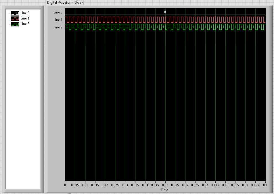
I use a PCI-MIO-16-1, and I'm trying to create pulses on each of the three digital outputs, using a hardware trigger. I got a solution that sort of market by using a loop timed; the loop runs once per trigger, and inside the loop, I use avoiding to turn each of the three outputs at the right time.
However, the problem is that the 1ms resolution of the timing of software is not good enough. So I try to find a way to do it using equipment, so I can get a finer resolution.
What I tried to do recently is to create a redeclenchables on one of the counters pulse train (using the example generate digital Pulse Train-finishes-redeclenchables) and use it as a trigger for the timed loop. I can get the pulse train to give me three ticks for every time that I get a hardware trigger and then put a state machine inside the loop to turn each of the outputs. (I am currently divide the material into three equal segments trigger.)
However, although I can generate the pulse train very well on one of the counters, I can't manage to get the timed loop to use this counter as its source of the moment. How can I do? Or does anyone have a better idea how to do that?
Unfortunately, the card you have does not allow for hardware timekeeping DIO. M series and recent X series Multifunction DAQ devices allow such a task. If you want, I can have a technical representative contact you to discuss your request and provide appropriate suggestions to optimize your application.
Kind regards
Glenn
Technical sales engineer
National Instruments
-
USB-6211 - digital output not supported?
Hi all
I can't use the USB6211 device port... I use daqmx with Delphi7 API functions.
First of all, I tried this:
DAQmxCreateTask('', @TaskDO);
DAQmxCreateDOChan (TaskDO, PChar('Dev1/port0'), ", DAQmx_Val_ChanForAllLines);
DAQmxWriteDigitalU8 (TaskDO, 1, 1, 1, DAQmx_Val_GroupByChannel, $FF, @written, nil);I had an error in the DAQmxWriteDigitalU8:-200012 (= digital output not supported). (???)
OK, I tried to disable autostart option based on DAQmxWriteDigitalU8 and insert a 'manual' start in the code:
DAQmxCreateTask('', @TaskDO);
DAQmxCreateDOChan (TaskDO, PChar('Dev1/port0'), ", DAQmx_Val_ChanForAllLines);
DAQmxStartTask (TaskDO);
DAQmxWriteDigitalU8 (TaskDO, 1, 0, 1, DAQmx_Val_GroupByChannel, $FF, @written, nil);
DAQmxStopTask (TaskDO);Now, I got the same error in DAQmxStartTask:-200012 (Digital Output not supported, once again). (?????)
I don't understand.. 'Digital output not supported "? USB-6211 has 4 lines! What is the problem?
I want to just turn on and off the lines from code...
-Cs George-
Well, finally I figured out...

Here is the solution:
DAQmxCreateTask('', @TaskDO);
DAQmxCreateDOChan (TaskDO, PChar('Dev1/port1'), ", DAQmx_Val_ChanForAllLines);
DAQmxWriteDigitalU8 (TaskDO, 1, @dummy, 1, DAQmx_Val_GroupByChannel, @bitmask, @written, nil);Digital output lines are on port1! Corrected parameter.
And the part of the interface of DAQmxWriteDigitalU8 had to be changed (in nidaqmx.pas).
I don't know why, but the AutoStart (dummy) parameter in the DAQmxWriteDigitalU8 function is ignored: function always starts task automatically, regardless of the value of autostart. But this isn't a problem for me.-Cs George-
Maybe you are looking for
-
In Thunderbird Deleting removes the server
I thought that if I delete the mails from Thunderbird (specifically) - they must also remove from my basket on my server, but they are not. Can someone advise? Thank you!
-
Version 4.0.1 will not allow exception certificate when it has expired
SSL connection fails with "an error occurred during a connection to 24xx:xxxx:x:xx:443. Certificate of the issuer of the certificate has expired. Check your date and time system. (Error code: sec_error_expired_issuer_certificate).Previous versions of
-
iMac 24 "aluminum, Intel 2.4 GBh, 4 GB ram, how do revive, no OS installed currently
New on Mac! Mine is an iMac 24 "aluminum mid-2007, GBh, 4 GB of ram 2.4 Intel processor. Problem is that this former owner deleted the operating system from the hard drive. Powered on, I can hear the DVD player, speakers put to the test with a sound,
-
Why the backup doesn´t Icloud Whatsapp appear in Icloud my player?
I ve got an iphone 6 (IOS 8.3) and backep upward from my conversations of Whatsapp to Icloud. But it doens´t appear in my Icloud drive. He says that my drive is empty. Thanks for any idea!
-
HP Envy 4500 Series: Failure print
HP Envy 4500 Series Recently installed above "All in one printer. Impressions on lazer standard copy paper OK but will not print on glossy paper HP? I tried to 180grm of 150gm paper weight. With the success of 'Hit and Miss' . I think it's a mistake