Wire terminal in diagram of Sub - VI Analyzer
When I run the VI Analyzer I get the following results
Class wired in diagram of sub-
That terminal control 'path of the log file' does not reside on the upper level diagram. To avoid memory copies useless, control and indicator of the terminals which are wired on the part of the connector must be placed on the top level diagram.
This brings me to the question-
Should the control terminals are located outside the case Error statement or between the case of the error and the case of the state machine?
VI Analyzer is pleased that when the terminals are outside the case of the error.
Jim
The 'proper' method is to do like the VIAnalyzer.
"Wrap-your-head-in-duct-tape", then read this thread.
I HOPE students to review who would know, but I can't speak for the 'right answer '.
Ben
Tags: NI Software
Similar Questions
-
Double-click the object of front panel to find the terminal block diagram
Hello world. I don't know why, if I double click on an object to front panel, labview opens the front tab customize, instead of finding control in block diagrams, which would be the normal behavior, as I read in http://labviewwiki.org/Tips_and_tricks#Debugging.
I tried to reset the initial Setup by renaming the file LabVIEW.ini, but it doesn't seem to work.
Do you know how double-click the object on the front panel and locate the?
Thanks in advance!
Guille.
Did you restart LabVIEW after you rename the file labview.ini?
There is an option (Tools... options...... general façade... 'Open the editor control with double click').
It always seems to be set in your case.
-
error "the type of the sink is zero.
I just made a change to a subvi to move terminal input. Control is a cluster type-def of 33 items. Everything that was done was to disconnect the Terminal in the connector sub - vi pane and move it to a different slot. Now when I try to rewiring of the sub - vi I get a cut wire and an error message "you have connected two terminals of different types. The type of the source is typedef ' Blah.ctl 'cluster of 33 items. The type of the sink is zero. This happens even if I click on terminal of the sub - vi of the upper vi and "create a control. The control is created successfully, but the wire is broken with this error message. Curiously, if I go to the subvi, create and identical order, wire to the open, the problem of the upper echelon is resolved. I tried to change the connector pane selection, forcing a repeat, no joy. I also tried to save everything and restart LabVIEW (v 2010 on Windows XP), got a "there was an error in the last run LabVIEW (fpsane) or want to solve problems. I get the error 'silent' crazy corrupt sub - vi?
"Tough luck" Seems I've corrected, but don't know how. I added the second terminal, it didn't fix it. LabVIEW, rebooted, no error message at startup. When I open the the original broken wire broken vi was no longer there, but there was still a broken arrow. Clicking on it showed a "phantom wire' connected from the most recently added (add entry only to try to duplicate a previous"fix") connected to a Terminal unallocated. Have not seen this before.
-
Why property nodes are not accept input?
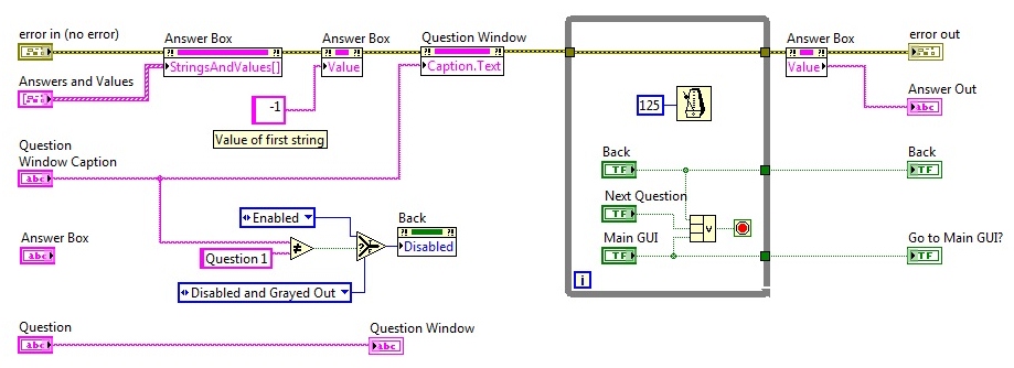
Well, this one is driving me crazy. I have a Subvi, which contains a string indicator and a drop-down list box, as well as a few buttons on the front panel. My problem is that when I run the program (in LabVIEW, not an exe file) sometimes the window Question (the light) accepts the string and updates the property of Caption.Text, sometimes it doesn't. At the same time, sometimes the answer box (combo box) accepts the Bay of cluster in it is StringsAndValues well, sometimes it doesn't. They both either work, or they do not. Never a problem with accepting Question window indicator string.
The block diagram:
Here is an example of the code powering the Subvi.
I don't get any kind of error message.
Sensors at the entrance of the property offending nodes indicate that the correct data are happened to them, it is just 'ignored '. Once it starts to spoil, it usually continues to do.
It seems that the only way I can get to behave correctly should quit LabVIEW, and then restart LabVIEW and run the vi. Then it will usually works a few times until it starts to work.
(Win 7, LabVIEW 9.0f3)
Thoughts?
THX
What is the source of the wire that goes into your sub - VI Q & A mistake? Is it possible that you have found errors on this thread?
If there is an error, these property nodes will not run.
-
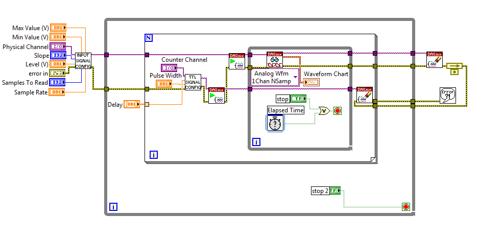
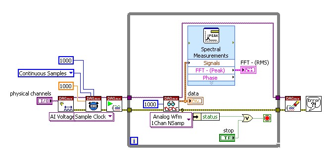
Triggers of analog input output meter with delay
Hello!
I am currently using a PCI-6251 DAQ card with a block of connection BNC-2120. I have a VI (one that is attached to this topic) that will essentially be an analog input signal and produce digital impulses from the output of the meter to each instant trigger. I am also able to define a series of delay values such that the delay will update automatically each at intervals specified by the user or when you press the stop button. I wonder if there is anyway to change this program as the time-out value will change every instant release. So, for example, in the first trigger a pulse is produced 0 second delay, then immediately when the next instant relaxation is reached, a push will occur with a 0.1 second delay, etc... And I want that the series of the time-out values to keep looping. I tried to use my current VI, with time to stop at each iteration to be less than half of the period, so theoretically it should go to the next delay value in the next instant trigger. Then I tried to put a certain time-loop around it to keep the job going, but it doesn't seem to work. I've attached a screenshot of my attempt, please let me know if this is possible, thank you! To see what each part of the VI in the screenshot, please see the screws attached, thank you!
P.S. for the VI that is attached, the analog input signal is 281Hz, the pulse width is 2.5% of the period and the delay is in the stages of T/20.
No worries,
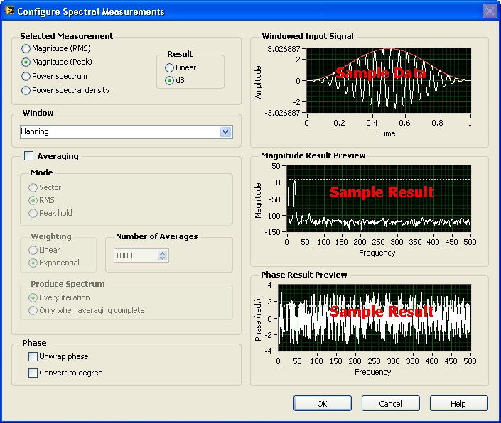
Please see the attached block diagram image. It is important to wire terminal on the Read.VI DAQmx acquire in a constant to the number ofsamples. This will force this function to wait until many samples are available in the buffer. In my example, you will get 1000 samples per second (because my rate is 1 kHz). and these 1000 were submitted directly to the FFT. What happened for example of you, it is only because you have not specified the number of samples to read, it is by default (-1), which means that the DAQmx Read.vi will pull all the data that is available in the buffer at the time. So if you had only 2 samples in the buffer that your FFT will have only two samples on average and as a result it will fail. Try this and it should help!
-
Why threads start and end at random?
Hello
I had the program below. I wonder why mark the beginning of discussions and put an end to chance? Every time I run the program, it produces different results.
I know these four threads have gotten the same priority normal (or 5) and under windows, there is only something called timeslice. These four threads then turn using this timeslice. How do we know what exactly the timeslice is in seconds? If the timeslice is fix, then why are the results random?
Thanks in advance!
/*
* To change this template, choose Tools | Templates
* and open the template in the editor.
*/
package mythreadone;
/**
*
Administrator of * @author
*/
/ public class MyThreadOne implements Runnable {}
String tName;
Thread t;
MyThreadOne (String threadName) {}
tNom = threadName;
t = new Thread (this, tNom);
t.Start ();
}
public void run() {}
try {}
System.out.println ("Thread:" + tName);
Thread.Sleep (2000);
} catch (InterruptedException e) {}
System.out.println ("Exception: thread")
tNom + "interrupted");
}
System.out.println ("completed thread:" + tName);
}
Public Shared Sub main (String [] args) {}
Why threads start and end at random?
new MyThreadOne("1");
new MyThreadOne("2");
new MyThreadOne("3");
new MyThreadOne("4");
try {}
Thread.Sleep (10000);
Thread.Sleep (2000);
} catch (InterruptedException e) {}
System.out.println)
"" Exception: main Thread interrupted. ");"
}
System.out.println)
"' Complete thread: main thread."); "
}
}
1. first of all, I put in the main function:
Thread.Sleep (10000);
and I run the program it gives:
Thread: 1
Thread: 4
Thread: 2
Thread: 3
Wire termination: 1
Wire termination: 3
Wire termination: 4
Complete thread: 2
Complete thread: main thread.
BUILD successful (total time: 10 seconds)
Run it again, it gives:
Thread: 2
Thread: 4
Thread: 3
Thread: 1
Complete thread: 2
Wire termination: 1
Wire termination: 3
Wire termination: 4
Complete thread: main thread.
BUILD successful (total time: 10 seconds)
And my question is why it displays like this? It suppose to be:
Thread: 1
Thread: 2
Thread: 3
Thread: 4
Wire termination: 1
Complete thread: 2
Wire termination: 3
Wire termination: 4
Complete thread: main thread.
BUILD successful (total time: 10 seconds)
Why these four threads begin and end at random whenever I run the program? I use Windows, assume that there is a timeslice (i.e. 1 second), these discussions have the same priority. Then the son must begin and end in turn one. Am I wrong?
2. my second question is:
When I change the codes of the 'main' function, in:
Thread.Sleep (10000); -> Thread.sleep (2000);
It gives me the results as:
Thread: 1
Thread: 4
Thread: 3
Thread: 2
Complete thread: main thread.
Wire termination: 1
Wire termination: 4
Wire termination: 3
Complete thread: 2
BUILD successful (total time: 2 seconds)
Run it again:
Thread: 1
Thread: 2
Thread: 3
Thread: 4
Wire termination: 3
Complete thread: main thread.
Wire termination: 4
Complete thread: 2
Wire termination: 1
BUILD successful (total time: 2 seconds)
I tried several times. The main thread always ends before or after the first child thread over.
My question is why he didn't come out something like:
Thread: 1
Thread: 2
Thread: 3
Thread: 4
Wire termination: 3
Wire termination: 4
Complete thread: 2
Complete thread: main thread.
Wire termination: 1
BUILD successful (total time: 2 seconds)
or
Thread: 1
Thread: 2
Thread: 3
Thread: 4
Wire termination: 3
Wire termination: 4
Complete thread: 2
Wire termination: 1
Complete thread: main thread.
BUILD successful (total time: 2 seconds)user13476736 wrote:
You can specify the reason please? See you soon.It's pretty simple. Start-up and execution of threads are not an operation of determenistic on operating systems that do not support hard real-time requirements. (Most operating systems do not support hard real-time requirements)
-
How to automatically run an order of series
Hello
I'm brand new on Labiew. I did a vi as attaché to the reader one shoot-syringe and rotary valve, and it worked fine. what it does is send command whenever I click on the button "pump" or "valve".
But now I want to run a series of commands automatically, for example, #1 à #2 valve, #3, and #4 to pump, pump pump of order total orders etc. will be around 10. I wonder what is the best way to carry it out.
Thank you very much
Make a (a typedef) cluster that contains for example information on the time and the type of order (I assumed you don't want different time controls)
Make an array of these "clusters of command" (or a queue, find out more about QMH) and stream to a state machine that emits orders at the right time.
If you are new to any of these concepts, learn about the documentation free before you start:
https://www.NI.com/getting-started/LabVIEW-Basics/
Moreover, you don't need the outside while loop. Instead, perform the shutdown affects a case in the structure of your event and the stop wire terminal to be true in the case of stop button.
-
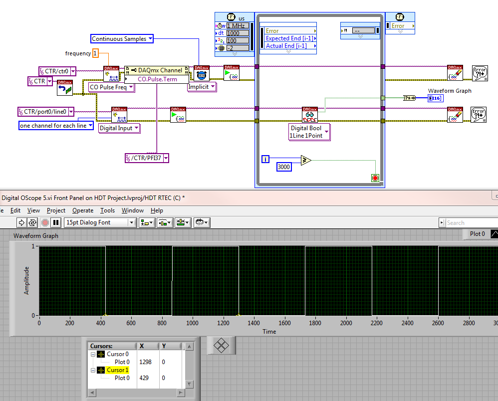
Cannot make digital scope of work
LV 2010, RT, PXI-6602
All I want is a simple digital scope to watch a digital signal which comes out a COUNTER and to judge if another part of my software works.
I struggled all day trying to make connections and finally abandoned - LabVIEW just won't do.
So, I managed to find a cable and get the connection through the material (oh - the horror!).
I start a course of meter.
I directs the output to a specific terminal.
I wired (with physical wire) terminal on a DIGITAL INPUT port.
I made a spot to read than digital entry port.
I used a timed loop to read that entry port a bunch of times.
Then draw the results.
No matter what I do, I read a different frequency than what I'm asking.
He's still 85-90% of the period during which I was expecting.
For example, I'm sampling the port here at 1000 uSec or intervals of 1 mSec.
A check of the END TIMES, or the State FINISHED LATE shows absolutely no error.
But look at the transition of a parcel is sample 429, the next is in 1298. That's a difference of 869 samples or 869 mSec.
If I try to 10 mSec, instead of 1 ms, I get 134-45 = 89 or 890 mSec
If I generate 10 Hz and sample to 1 mSec, I get 138-48 = 90 or 900 mSec
So, which one is lying to me?
Is it really generate 10 Hz and I am in a position he bad?
Or am I just measure and it generates really 11.1 Hz when I ask for 10?
For example
-
Zipped VI is fixed, the upper level has "7_AD-DC producer consumer" as the title. You will have to dig into the folder for access.
I have attached a picture of the Vi, highlighted in red is the loop in question.
The problem I have is that when I run the vi has the range of 0.25 to 0.5 Volt (chosen in the loop of producer not shown), it works fine, but if I run the vi put on the beach of 1 volt, it ignores all highlight loop, and finishes just the event.
The program aims to help the particular device calibration. If you follow the path of the error, it crosses the upper part (1605, 1605 mode range, range of AC - DC, the factor N, etc.) all the way through the indicators for "1 k reference in ' and ' 1 k reference on. The program runs right up through these measures of reference, but when it is in range Volt 1 (shown in the picture) it ignores the entire for loop. I son of error in all, and I thought that those who would prevent race conditions and they would oblige the Vi to run as expected, but apparently not.
It's kinda a Vi spaghetti, I'm not the best with LabView, but it seems so strange to me that it works when the value 1/2 a volt but don't not 1 volt value. I put the indicators on the elements that fuel the loop For, the number of frequencies and the tables of frequencies look good and I can't really think what causes violence to ignore the loop for.
The for loop is not in 'jumps' it of executing 0 times and out of default data for all tunnels.
You have an entrance tunnel auto-indexé why wire terminal N at all? The loop will be the least number of iterations it can. N times, either the smaller auto-indexd table is something less.
EVEN worse: the indexed table auto comes from a tunnel exit case structure value "Use default if unwired" so you have two options. There is a hidden code clear the Board before being sent out of the cases showed, OR the value of the number of frequencies is<>
-
several mode sequential slave modbus w/r
Hello
Looking for a few good tips.
I use the library or labview modbus RTU mode, using a USB converter to 485. The library works very well as expected and performs all read/write operations that are implemented in the library.
I'm trying to design an application to control 20 slaves to perform a simple operation, read a record of each slave, assess the value and increment a counter, if the value read is a '1 '.
Now the application must be automatic, kind of push button 'Start' and then run sequentially writing to each slave, wait 5 minutes to perform the operation and then read each one updated register, day the meter... and vice versa... continuously until you press "stop".
I started to prepare the application with a flat sequence structure, with a first diagram of sub containing the operation of writing and then wait 5 minutes and the second overtime scheme would undertake reading and update counters.
(1) first problem I encountered is very stupid, how to increment the registry value to treat slaves sequentially in the sous-schema first effectively.
Counsel on how to do it?
I tried a loop (see table) and the use of the index of the iteration to try to increase the address register, but I struggle to convert the data type... is there an easy way to do it, for example to ensure I send the command twice to each slave?
Ideally I would like to send command to #1 slave and the slave then #2.etc... but I don't know how to do this.
(2) how to stop running for 5 minutes to let the slaves work and then proceed to read?
-
I cannot repeat a menu choice?
Y at - it a shortcut to a menu selection? For example, I just realized that I have a series of threads that I need to insert a Negate in. I click with the right button on the wire and go through 3 submenus to get the negate. For the next wire, I go through the sub-menus even once again. It would be great if right click gave you an option to repeat the previous function with a menu item that says "repeat - insert Cancel" or whatever the previous function was.
Try a quick decline
http://forums.NI.com/T5/LabVIEW/Darren-s-weekly-nugget-08-02-2010/m-p/1202725#M516850
-
Hello!!
In my application, I first want to display a page with my logo and "proceed button" to move forward. After clicking this button, I want to enter another Panel to enter my communication settings. And when you click on "proceed button" I enter the main VI which displays the acquired data. If I make these three separate screws how can I link them or how can apply this logic?
THNXX!
Concerning
DeWalker
AUTONEWS.nl
DeWalker,
You could use a sub - VI to get the comm settings and avoid using VI server altogether; This way you can wire the outputs of the sub - VI to anywhere you need. I think that's what suggests Weibe & parthabe; have you tried that?
You can use functional global variables to store the settings, if you need to separate your screw those who are VERY useful; consider them if you are not familiar with their use. Shared variables are my favorite less characteristic of LabVIEW. Never use them!

-
Stopping at two while loops, running with queuing
Hi all
I'm using labview 8.2.
I have two while loops in my code (called the main loop and the other average loop - seen on the screenshot file). I just want to stop both the while loop at the same time (it's ok it the average loop takes a bit longer). I use global variables to stop (as I have tried the local one, but I don't think that LabView sees in the middle of the subroutine).
Please give me some suggestions on this.
Is attached a screenshot and my labview code
Using a ' functional global' is almost identical with a "global" variable Indeed, before the existence of "global variables", a functional overall, it is how people have this feature.
The usual way to stop a loop containing a "wait for queue ' is to destroy the queue and use the error on the terminal of the 'expectation of queue' directly in the terminal of the judgment. In this way, you don't have to queue up some kind of end the command to stop it.
Add a queue to destroy after the stops 'main while loop. Delete the global variable and the error from the stop "waiting in the queue" in the loop "average" it is wire terminal.
General advice, always try to avoid using local and global variables.
-
Hi, I just bought a SPA9000, and I wonder if I can set for direct ip calls.
I use the FXS 1 on the spa9000 and line 1 is already on my VOIP provider.
PBX settings
Call the routing rule: (4xx<:L1>. |) <:L2>8xx. | <:L3>7xx. | <:L4>6xx.)And 1 line numbering Plan is:
(<> <:@mydynds.com:5061>xxxxxxx)
Therefore, the call and the newspaper
-----------------------------------------------------------------------
[3] RegOK. NextReg in 58 (1)
2. number of report 1 (1)(40 ms)
Calling:[email protected]:6060
[0:0] DIAL the ALLOC AUD (port = 16434)
[0:0] RTP Rx upward
[JIU] CallRoute:L144549141
PRI--> INVITE--> pub
Calling:[email protected]:5061
Bcc:ringback / CallProgress 2
CC:ringback
[0:0] RTP Rx Dn
Pub - 200--> CCI - 200--> pri (appeal)
[0:0] ENC INIT 0
[0:0] RTP Tx Up (pt = 0-> c0a80165: 16438)
[0:0] RTCP Tx upward
----------------------------------------------------------------------
But after some time 20 seconds or maybe less she then drops the callRespLooseMatch
[0:0] 16 (2) LAT -.
RespLooseMatch
RespLooseMatch
PRI says BCC GUEST: pri - 200--> CCI - 200--> pub
CC: finished
[0] alert FM stop RxTx (c = 002c67dc; a = 0)
[0:0] call of Rel AUD
359dc0 terminated DLG
Sess end 3668ec
TP Analyzer error: 34
[0] on the hook-----------------------------------------------------------------------
Any ideas?
Thanks in advance.
I tried to research on your problem and I found another element which may help us: Lets guess 2 devices and b. also allows assume address IP is 192.168.1.50 and B device IP address 192.168.1.51.
Configure these settings in device A:
Step 1: Line 1 tab, set port SIP SIP settings section: 5060.
Stage 3: In line 1, Proxy and registration section all the empty fields or no. except to call without Reg: YES and years without Reg: YES.
Step 5: Tab of row 1, section of subscriber information full name value:user ID: 11 and leave the other fields swamp.
Step 7: In the tab section of plan Dial Dial Plan of line 1 on the Court together (21S 0<:@192.168.1.51:5060>), enable the IP numbering: YESConfigure these settings in device B:
Step 8: Line 1 tab, set port SIP SIP settings section: 5060.
Step 10: In line 1, Proxy and registration section all the empty fields or no. except to call without Reg: YES and years without Reg: YES.
Step 11: Tab of row 1, section of subscriber information full name value:user ID: 21 and leave the other fields swamp.
Step 13: In the tab section of plan Dial Dial Plan of line 1 on the Court together (11S 0<:@192.168.1.50:5060>), enable the IP numbering: YESNow, how does it work:
-To call device 1 line of device (any line) B dial 11.
-To call device B line 1 of the device (one line) dial 21.This has proved works with two SPA phones that are configured in the same local network segment. But in you I thing deal you make IP dial in on a remote network that would probably be another network. In this case, I think that you must configure the VPN between the network where the SPA-9000 and the other phone remotely. Then configure the IP numbering as as it is done in the above procedures.
I hope this helps.
-
Problem with Terminal, input sub vi
Hi, I added a terminal to one under vi (trying to add an entry to accept a string entry). When I display the contextual help of the Terminal comes with a pink wire, but when I select the sub that is not possible to add the right input does not appear the vi in the schema of the new terminal. the Subvi is used in several places, and the program will not work until I have add the input string at each location the sub that VI is used.
Thank you.
If the Subvi appear greyed out, try right-click and then re - bind to Subvi.
Maybe you are looking for
-
Satellite Pro A100 has "limited or no connectivity" & no connection to the local network
Hello! I + really + hope someone might be able to help with this - been going slowly crazy. Bought my A100 18 months ago in Australia while I lived there and had no trouble to connect to LANs and others with my wireless. Everything was shipped over t
-
Get the 5 error: the file is open
I'm having a problem with my VI. I want to create a file every minute and write at a high resolution for this minute. Then after the minute is made and im writing to another file, delete the file I wrote it just to. I can create files very well, but
-
I have Windows XP sp3 ie8 & 2009.I messenger can't connect to messenger, use messenger... NOTHING! I'm p * d stop waiting for a response. He said that there is a new download available? so when I download... then he says nothing has been downloaded a
-
Clicking on a file crashes to explore
When I say RH click a file in My Documents to look at properties, or rename etc... It blocks to explore. I opened the window of the closed folder and Explorer seems to stop and immediately restart. It doesn't do this on say LH click of the mouse.
-
Printer HP deskjet 6940 with Windows 7 problem
I have a HP Deskjet 6940 printer that doesn't work with my Windows 7. This can be corrected?