written boolean unique to the module of digital output or 9472
I have a vi who writes in both modules of analog and digital, 9263 and 9472.
I don't have a problem writing to the analog modules, but the modules digital (9472) gives me problems. I want to write a single Boolean value, and he wants a Boolean array. I was using the DAQ assistant, but dropped on it. I'm probably not understand how to access the port correctly.
I've included a partial copy of the code. (LV crashed when I tried to create a snippet of the original code, so I had to copy it to a new vi.)
You have not included the Subvi and if you want to generate a single Boolean value, it is absurd to use the Dig generate 1 D data and instance of DAQmx writing. Just use 1Line 1 point. Change the instance by clicking on the polymorphic selector under DAQmx writing. Select Digital > single channel > sample > Boolean. You can also use the DAQ Assistant by plugging in just a function table built between the Boolean command and the input of signals.
You must also consider writing your code without globals.
Tags: NI Software
Similar Questions
-
Control the Boolean commands and generate a corresponding digital output
Hi all
I'm working on a project of activation of the electrode, here, I thought that how could I order an electrode in a time and generate a digital output of it accordingly. I want to replace it with each electrode with a LED on the front panel and generate a numerical value to each LED on the block diagram.
If it can be divided into two parts
1 control the Boolean outputs
Here, my goal is that if I have 5 leds that are used as a Boolean control, must be ordered so that only one of them lights up at the same time and the rest goes off.
I mean for example if #3 was turned on and that the user pressed the #3 #2 should be turned off and only #2 lights.
2. generate the corresponding numerical value
Depending on the position of the LEDs I want to generate a corresponding numerical value, as previously released 3 coming and exit 2 then comes when the second LED illuminates.I ask all participants to this group to help me with this.
Concerning
Why don't you use the radio button control? You can replace the boxes if you want the buttons.
-
How to secure the wiring of digital output BNC-2090
Hi, I'm working on using the digital output of data acquisition to control the digital DAC input, but I have a problem on how to fix the wiring for the digital output of the DAC. When I plug the cable into the hole, it is vaguely related. Any suggestions on how to fix the wiring are appreciated.
Thanks in advance!
It is a spring terminal.
Try to push in the orange tab with a screwdriver while pushing in the thread. Release tab to release the wire, and it must grab and hold the wire. It may be a case involving Orange instead of push. You should be able to understand.
-
Route of the exits of the same meter, digital output
Hello
I'm not sure it's possible, but I will deliver the outputs of 2 meters (PCI-6602) on the same line of digital output.
My 2 meters each generate a pulse train defined by frequency, cycle of dut and delay. I want to combine 2 pulse trains in a pulse train resulting. How would it possible if I can't deliver the outputs of the counters on the same digital line? What I have to abandon this idea and set the desired binary pulse train and release several times what a digital line?
Thank you very much in advance for all your comments here.
Cheers, Shaun.
Hi Shaun,
I do not recommend you to connect directly 2 outputs.
Why not use a door or 2 entries? Connect the outputs of the meter to the doorways.
If the impulses are well timed and synchronized (they do not appear at the same time)
the output of the gate or will be a combination (in short, actually) of these pulse trains.
Hope this helps,
-
synchronize the inputs and outputs of the module C digital 9403
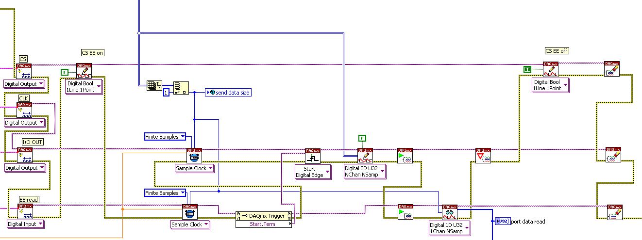
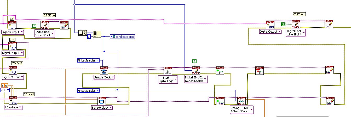
I want to program EEprom with 9403 module, but I got an error:
Possible reasons:
Specified route can not be satisfied, because it requires resources that are currently in use by another route.
Source device: cDAQ2
Point source: di/SampleClock
Target unit: cDAQ2
Destination terminal: Slot1/ConvertPulseResources in use by
Task name: _unnamedTask
Source device: cDAQ2
Terminal: / SampleClock
Target unit: cDAQ2
Destination terminal: Slot1/ConvertPulseTask name: _unnamedTask
code:
Okay, there are two levels of problems:
the 9403 cannot use a timed with an easy task, and it cannot link di trigger with trigger, uff do!
I solved with this: (the trigger is AI/StartTrigger)
-
the pci-6238 digital output current
Hello, I referred to the NI 6238/6239 specifications, but I've not seen this specification.
I wonder if the maximum output current is the same as the current (9mA) of entry?You can check this link for the information you need:
http://sine.NI.com/NIPs/CDs/view/p/lang/en/NID/202503 -
Problem with a digital output in the information of an analog input
Hello
I use a SCXI-1000DC module with a module of the SCXI-1600, SCXI-1531 module and SCXI-1163 module to receive an analog of an accelerometer signal and a digital signal.
I claim that the accelerometer is constantly monitored, and the output is on when I want to, by an impulse that I comand in labview.
I use a rate 25 k and a 12, 5K samples per channel on DAQmx Timing.I notice in DAQmx read, if I put a sample of hight by channel, the output is not there when I want to, and if I put a few samples per channel, I exit when I want to, but the program seems to be slow with the passage of time. I don't know how I can solve this problem!
I'm sorry for my English, and I hope you can help me.
Thank you
Silvia
Hello Silvia,.
If you ask a larger number of samples, the labview diagram will stay longer in the DAQmx Read function, so the while loop runs slowly, and the digital output is updated less often.
I suggest that you use 2 separate while loops: one for the analog input and the other for digital output, so that each loop might run at a different speed.
Best regards
-
NI USB-6501 digital output problem
Hello
I use DASYLab v.11 and I'm working on an interface with the NI USB-6501 where I'm putting a digital high on four ports.
With the module "NOR-DAQmx - digital input", I managed to read the digital inputs of the ' NI USB-6501 ".»
It's only the "NOR-DAQmx - digital output" I can't go to work.
Using 'NI MAX' of NOR I have easily can emmit my four LEDs in the way of my High/Low ports.
But not with DASYLab. When you use DASYLab tension on the ports remains unchanged.
Now, I have a switch module, generating 5/0, directly connected to the digital output module, which is assigned to my four output ports for my task.
I also tried with a module of relay between the two without success. I also tried to use 1.5 above instead of 5 without success.
I use the option 'Bus (0/5 supply) for the module "Digital output".
"NI Max", I configured the ports as "active drive.
Any suggestion of what I might be missing?
Thank you
Martin
Hmm, four ports, or four lines?
A port consists of eight lines. Each line can control an LED (ON / OFF ~ 0/5V).
If you have created a task to dig-out to control a port, 5V to this port sending sets all lines of this port to 'high '.
You need to 255 for each line one too high port (at the bit level: 128 + 64 + 32 + 16 + 8 + 4 + 2 + 1).<- eight="">
Or, you can create a dig out tasks to control four lines of a specific port.
Four lanes of the EEG DAQmx DigOut module.
Each of the channels of the modul will feed a single line of the task/device.
Four switches will then turn the lights, or turn off.
Make sure, that the 'bitposition' is the number of correct line (see picture).
-
USB-6211 - digital output not supported?
Hi all
I can't use the USB6211 device port... I use daqmx with Delphi7 API functions.
First of all, I tried this:
DAQmxCreateTask('', @TaskDO);
DAQmxCreateDOChan (TaskDO, PChar('Dev1/port0'), ", DAQmx_Val_ChanForAllLines);
DAQmxWriteDigitalU8 (TaskDO, 1, 1, 1, DAQmx_Val_GroupByChannel, $FF, @written, nil);I had an error in the DAQmxWriteDigitalU8:-200012 (= digital output not supported). (???)
OK, I tried to disable autostart option based on DAQmxWriteDigitalU8 and insert a 'manual' start in the code:
DAQmxCreateTask('', @TaskDO);
DAQmxCreateDOChan (TaskDO, PChar('Dev1/port0'), ", DAQmx_Val_ChanForAllLines);
DAQmxStartTask (TaskDO);
DAQmxWriteDigitalU8 (TaskDO, 1, 0, 1, DAQmx_Val_GroupByChannel, $FF, @written, nil);
DAQmxStopTask (TaskDO);Now, I got the same error in DAQmxStartTask:-200012 (Digital Output not supported, once again). (?????)
I don't understand.. 'Digital output not supported "? USB-6211 has 4 lines! What is the problem?
I want to just turn on and off the lines from code...
-Cs George-
Well, finally I figured out...

Here is the solution:
DAQmxCreateTask('', @TaskDO);
DAQmxCreateDOChan (TaskDO, PChar('Dev1/port1'), ", DAQmx_Val_ChanForAllLines);
DAQmxWriteDigitalU8 (TaskDO, 1, @dummy, 1, DAQmx_Val_GroupByChannel, @bitmask, @written, nil);Digital output lines are on port1! Corrected parameter.
And the part of the interface of DAQmxWriteDigitalU8 had to be changed (in nidaqmx.pas).
I don't know why, but the AutoStart (dummy) parameter in the DAQmxWriteDigitalU8 function is ignored: function always starts task automatically, regardless of the value of autostart. But this isn't a problem for me.-Cs George-
-
What is a digital output (DO) good for?
Actually, I wanted to use the outputs digital to move from a 24 VDC circuit (to turn on/off other devices etc.).
But the current output outputs digital is so low that I have even impossible to pass an opto-coupler (opto isolator).
That's why I wonder you use outputs digital for if you cannot use them to change anything?
Of course, I can create a circuit MOSFETS or transistors to switch 24VDC power with the TTL 5V digital output signal. But I guess that most of you do not :-)
And of course, I know that I can buy OR relay modules/cards. In fact, I have many digital outputs available and do not want to buy new modules/cards.
Now, I can test and actually I get 10mA @ 5V on a digital output of NI 9401 (DIO), using the digital output to pass an opto-Coupler.
It seems that the information contained in the data sheet are supposed to mean something else...
-
PXI-6120 digital output frequency
Hello
before that I have to post my question some technical information:
LabVIEW: 2011.
IO digital 8 PXI-6120.
I read the user manual and search the Forum and there is no reference to the frequency of digital output (only for a meter).
My question is what is the maximum frequency that I can generate outputs digital?
The best I could do is 50 kHz using the example.
Thank you
Sokal
-
Hello
Here's my problem: I want to generate digital samples (10-bit) whenever I get a digital external trigger.
This should be easy since I could still do it with the express DAQmxVI.
But the switch can go up to 120 Hz and 16Hz, the generation is not fast enough. It seems like the writing of digital output configuration takes too much time on each loop.
I don't know I'm missing something... can anyone help me on this or point me to some documents that I could use?
Which would be very appreciated.
Thank you
R
PS: I use a NI6351 USB card to get the external trigger on PFI0 and write the numeric data I want to send.
I found the answer and share the link here:
https://decibel.NI.com/content/docs/doc-25189
Thanks to Nathan-P!
Basically my USB6351 NOR is not redeclenchables, otherwise, you just add a property trigger Daqmx with redeclenchables true node. But with this thing, it works great!
R
-
Original title: unplugged... HDMI?
So I have a laptop Vaio of microsoft. The microphone that was integrated into the laptop was working fine until recently. No, I talked through my laptop was able to hear me except through Skype. I search through my laptop and say something like in the playback than digital output device or interface (HDMI) was disconnected. I know very well that I unplugged it. Can someone please?
Hello
1 did you change on your computer before this problem?
2. you receive an error message?
3. What is the exact make and model of your laptop?
4. are you able to record from Microphone?
5. which version of the operating system is installed on your computer?
What version of the operating system Windows am I running?
http://Windows.Microsoft.com/en-us/Windows7/help/which-version-of-the-Windows-operating-system-am-i-running
Make sure that the Microphone settings are set up correctly.
a. right click on the Volume icon in the notification area.
b. go to recorders and right click on the empty area.
c. Select Show disconnected devices and show disabled devices.
d. right click Microphone, and select activate.
e. Microphone right click and select Properties.
f. Select the option use this device for the use of the device falling down.
g. go to the levels tab and move the slider to the maximum level.
h. click on apply and OK.
See also:
Tips for solving common audio problems
http://Windows.Microsoft.com/en-in/Windows7/tips-for-fixing-common-sound-problems -
FPGA code with the evolution of the modules
I need to create FPGA code to a cRIO-9072 facing the development of the modules.
My cRIO will have a number any NI 9203 (analog acquisition) and modules OR 9411 (acquisition digital) as inserted by the operator. When turning the power on, the system must identify two possible modules were inserted in each of the slots. Subsequently, he will then know what choices of code to call to acquire data from the individual modules.
I found the article in the knowledge base for CRY that queries each module and again reports the type of module and I can use it to successfully detect modules, but what LabVIEW fails to allow me to do this is to compile my FPGA code that was designed to deal with possible modules. After compiling, I get the error: "IO found point FPGA project. You must add the I/O item in the Project Explorer window, or select a different element in the control of FPGA of IO or the constant"because the compiler requires the appropriate modules are configured in the LabVIEW project. Unfortunately, this would require two different modules to be configured for each slot at the same time as there are sections of code for the 9203 modules and sections for 9411 modules for all eight locations coexist in a vi.
Anyone have any ideas on how to get LabVIEW to compile my FPGA code somehow?
Many thanks in advance,
With the current draft of LabVIEW FPGA, you cannot compile a LabVIEW FPGA VI which manages several configurations of C Series modules.
For your application, you must create a target of your project for each of the possible configurations of module and build the corresponding FPGA VI. Then, compile each of the screws to create the necessary for each configuration FPGA bitstream. Then in your host VI, you can detect what the current configuration of the module and download the binary stream appropriate for the FPGA. Another issue to consider is that the reference to the FPGA VI/bitstream returned by the open FPGA VI reference function will be unique to each bitstream/module configuration. So in your host VI, you'll need treat each configuration of the module with a separate set of code by contacting the FPGA.
If you consider only two different modules and an eight slot chassis, there are 9 modules possible combinations. The condition would be to the end user to place all modules of the same type together, either from the left or the right side of the chassis.
-
Fortunately the cRIO merger two time real screws: analog and digital output
Howdy,
I need help with a cRIO code. The purpose of the code is to acquire an analog input from the NI 9234 c series module and be able to send a "signal of pulse" digital camera (first low for some time, t1, then high for some time, t2) from a NI9401. Separately, I wrote the code to perform both tasks. However, when I add the code of RT digital output pulse pulses to analog input RT code, the DMA FIFO overflows because of the way that my digital pulse output code works. Currently, there are two reasons which overflows of the FIFO:
- The digital output code is pending for a while loop (pending "Send Pulse" become a true), the loop I can't empty the buffer FIFO
- The FIFO is not enough, quickly emptied depending on how long the pulse (t1 and t2) times are. The way I keep the pin high or low for a defined period of time is by issuing a sleep command, which blocks the loop I empty the FIFO. (Is there a "best" way to sleep?)
I have attached photos of my codes FPGA and RT. Please give me a suggestion on how to marry my two loops of RT for the use of happy resources! Thank you.
I found a quick way to solve this problem. I moved the timing of the Digital pulse on the FPGA. So whenever I have a Boolean value, the FPGA generates a waveform with the settings I put (a pulse in my case). This works because the FPGA loops run in parallel, I think. That's why, when I run a pending order in the loop of FPGA digital output, it does not prevent the FPGA of analog input loop to run. I have attached a picture of the code.
Maybe you are looking for
-
Satellite A200 - 1 GB Vista - SVHS output photo Yes - sound not
I have connected my TV out SVHS following the instructions in the manual A200. I get a picture but no sound.When connected I can't find the sound SVHS design in the sound Applet in Control Panel, I see that the speakers of the system. Please can some
-
Keyboard yoga 900 arise does not in Tablet Mode
I've had settings and devices and clicked on the box I was supposed to click on. In TABLET mode, when I touch the Google to enter text inside bar, the keyboard does not appear, so I have to manually launch the keyboard then when I finished I have to
-
Why 'Read a fixed number of samples' help with the error 200279?
Hello world It is a question about a tip found in the explanations on the acquisition of data error-200279. This explanation it is said: '... ". reading a fixed number of samples instead of all available samples can fix this... » AFAIK the DAQ system
-
I have a Toshiba laptop w/windows 7 & a hp 1610 printer, how can I ink ck levels?
I have a Toshiba laptop w/windows 7 & a hp 1610 printer, how can I ink ck levels?
-
When I scroll a page all of a sudden the page jumps all the way back to the top
When I scroll a page all of a sudden the page jumps all the way back to the top