4071 PXI get negative resistance readings
Hi all
We are working on a system where we measure current leakage and resistance using a PXI-4071 with some other gear as well as a map to relay SMU and 2530 b..
The main problem is that for some measures of resistance we are seeing negative values as k - 200 or - 300 k. The digital multimeter has been in the range of 10 M. My understanding is that in this mode, the applied voltage is 10V and the test current is 1uA.
For me to see a negative resistance on some paths, the voltage must be opposed the 10V and superior to 10V. Is it a specific way of thinking? SMU is switched off and disconnected from the circuit when the resistance is measured.
It is not all EHRS that show this negative tension. The EHR is all passive devices (connectors) and so they do not have any large capacitances that could store a tension that I see. I take 5 readings with auto zero done when initially 5 readings.
What causes these negative readings? The connectors are immersed in a saline solution and there should be an open between the points to measure circuit, but when they start to fail a resistance can be seen.
Any thoughts would be much appreciated. Please let me know if you want more details.
see you soon
Peter
Peter,
To answer your questions, Yes, if the digital multimeter reads - 200 k there is opposing tension on the DMM. If you use 10 M Ohms then the opposing voltage serait.2 V and if you use the 1 M Ohms then the opposing voltage 2V. Also the negative reading is also caused by the flow of the current is in the wrong direction, because if there is a negative voltage then the current flows the opposite direction.
You can check the voltage at the terminals of the resistance while taking the measurement of the resistance using an other DMM, as a handheld DMM computer. It is more than accurate enough to check the voltage at the terminals of the resistance.
I hope this helps,
Brian P.
Tags: NI Products
Similar Questions
-
How can I get negative numbers on my spreadsheet of numbers to be displayed in red.
How can I get negative numbers on my spreadsheet of numbers to be displayed in red. The only thing that I can find in the menu turns formatting all the red cell. Not what I want
Use the conditional formatting.
Select the range of cells you want to format, and then open cell formatter:

Now click the button of "conditional highlighting:

Now click on the button «Add rule...» » :

Now choose the rule "less to" a value of zero and choose the selection of red text to highlight
-
his strong 'Willy': niSwitch DMM PXI switch Handshaking.vi 4071/PXI-2527
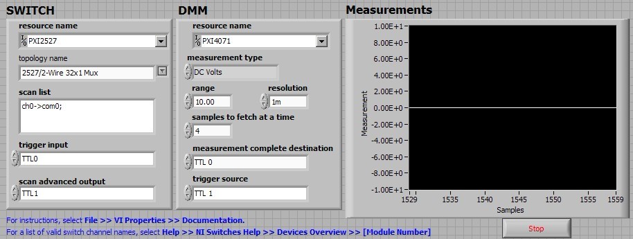
I run the example of the handshake: "niSwitch DMM Handshaking.vi switch" for 2527 PXI DMM PXI-4071/SWITCH in a chassis PXI-1033 for a measure of 1 Volt DC test.
When I type 'Run', the switch block makes loud continuous noise "zizi"; the graph of 'measures' simply gives a 0 volt line. It's clearly wrong results.
My setting of this VI is as follows:
Anyone know what is the problem here?
Thank you
Bing
BLNG,
This noise is actually the sound of the relay control. Given that these relays are electromechanical relays, when the relay is closed, the two contacts essentially slap against each other and produce this noise. The buzzing you hear continuous, is because the relays are opening and closing several times. If you use the appliance in OR switch Soft Front Panel for example, you can hear a click by relay which is operated and closing individually each relay.
-
Changes in the driver vi using the Simulation Interface Toolkit (SIT) for PXI get do not appear.
Hello
I use Simulation Interface Toolkit to target a controller built in Simulink on a PXI target. I used the SIT connection manager to generate the driver screws I had to make some changes in the screw driver specifically Read.vi IO. I made the changes and the entire application runs without error. But the changes are not getting in the functioning of the application, essentially when I load the thing on PXI and run it, it contains exactly as it was before behaiving I made these changes. Some how the changes I make to the Read.vi of e/s are not begin day somewhere in the top vi driver.
Could someone help me with this please.
Eliane.
Hi Justin_P,
Thank you very much for the reply. Solved the problem. What you're saying, that's certainly true, but I do not use the project.
The problem was that whenever it makes a change one driver that saw VI top-level driver must be opened and saved again. This opening and registration links the pilot with new changed correctly VI and then everything works fine.
Thanks again.
Eliane.
-
Problem of reliability data acquisition PXI-4071
Hello
I'm having a problem of reliability using my 4071 Pxi digitizer mode.
I have a number of tests that use the SMU-6363 (usually configured for DC) analog output to provide a stimulus for our own device, which has a number of a/d converters. We use the PXI system for calibration and testing.
1. I select a voltage ranging from tensions.
2. program the PXI-6363 to drive this tension
3 TIME about 10ms to settle. Note there no discrete capacitors or resistors in the circuit. Everything is parasitic and would generally be under the nF mark and less than 10 ohms
3. configure and Initiate() acquisition of data with the PXI-4071. In general, I use a sample rate of 1000 s/s and get about 30 samples (worth 30 ms). Activation is immediate and I used the default a queue time, 0, set the time and it doesn't seem to make a difference.
4. measure the voltage with the CDA. For debugging purposes I have sometimes made twice once before calling Initiate() and once after. The after is normal. The time required to measure the ADC is shorter than the acquisition time, but regardless of stimulation by the SMU-6363 is constant
5. extract the waveform.
6. the average waveform and compare the value of ADC measured by applying tolerances etc.
Here's the problem: it works well most of the time. But only 0.1% of the time (1 on an acquisition of 1000), I get 8-12 samples that are close to 0. It sounds like a problem of time settling (on the surface), but no matter the amount of wait time data, I always get this behavior. Not only that, but the tension before the call to Initiate() in height CDA, it always confirms that the motor voltage is already set to the programmed value. Nevertheless the acquisition presents near data 0.
So far our independent ADC always reports the expected before and during acquisition (100%) voltage. It's like the DMM input is disconnected during the acquisition during a period of time, because we have confirmed that the voltage is already present prior to the acquisition (component can). I have no errors the insider or FetchWaveForm calls. I still have all my samples. And 99.9% of the time that everything works as expected.
The DMM and ADC are connected to the same point and both are referenced to ground, and as I said before only the parasitic capacitance and resistance (cable). We use a matrix of switching (PXI-2530 (b) to make these connections. We almost always use 51/2 digits and 10V range for data acquisition.
Hello
I thought about it and was going to repost but am distracted.
The device with the ADC also has a mux and switches the mux to an internal node. It only switches when measuring and is open at other times. There is a race condition where the acquisition starts too early and maintains the acquisition after that the switch is open. Unfortunately I don't have the option to trigger.
I forgot the internal mux that I had designed the test years ago and I did some updates to improve the stability of the test. That's why we start the ADC measurement when acquiring.
I just added a routine to reject samples below a threshold
-
Error-1074118625 with the PXI-4071 and PXI-2527
When you use the LabVIEW and PXI-4071 PXI-2527 IVI drivers, I get a 1074118625 error in TestStand. The sequence that initializes the MUX, init DMM, connects the MUX, expected debounce, and then to the DMM reading, I get this error.
Error: niDMM .viExplanation of waveform (waveform data) reading is not found for the requested status code.
Check that the required status code is correct.
[Error code: error code defined by the user of 1074118625.]
This sequence of events is used successfully several times elsewhere in the TestStand. This error does not appear in any section of the knowledge base, or any help. Any explanation would be greatly appreciated.
I found this with google that seems like it could apply:
http://digital.NI.com/public.nsf/allkb/A593DEBFD86A69C68625727900748EEC
-
How to acquire data through several channels in parallel using E 6070 PXI, PXI-4071 and LabVIEW?
Hello
I use LabVIEW and NI PXI-4071 PXI NOR 6070E to measure the current through a variable resistance. Now, I use a single channel of SCB - 68, but I want to add another channel at the same time so that I can have two resistors instead of one that I cam measure current through them.
I have attached a Pdf file showing installation of equipment to use and code LabVIEW also.
Can someone look at these files and give me some guidelines or ideas that can help me solve this problem, please.
Thanks in advance.
Best regards
Shaheen.
Your 4071 can do a measure at a time. Your data acquisition cannot measure resistance is not she of the analog inputs.
However, you could use a multiplexer and multiplexer your 4071 DMM. This habit give you simultaneous action, but can acquire data one after the other, the speed depends on the multiplexer, you choose!
I hope this helps.
-
Hi all
What is the difference between
"SQL ORDER BY GETS."
"SQL ORDER BY BED.
In the documentation I found that 'GETS' = 'READINGS LOGIC' and 'BED' = "PHYSICAL READINGS"
In oracle, what is the difference between 'PHYSICAL READINGS' and 'LOGIC BED'
Please help me with this.
Kind regards
VAMSi.Hello
Read this... can help you understand.A logical read occurs when a user requests data from the database. It occurs every time that the
the data is in the buffer cache or if the user process must read from disk. If the data must be
reading disc then a physical read occurs. Oracle keeps track of logical and physical reads
table V$ SYSSTAT.Use the following SQL statement to determine the values needed to calculate the hit ratio:
Select the name, the value of v$ sysstat
WHERE name in ('db block gets', ' Gets consistent ","physical readings");The rate of access to the cache can be calculated as follows:
Hit ratio = 1 - (physical reads / (db block gets + gets compatible))
If the rate of access to the cache becomes less than 90% then:
Oracle 8 or earlier version: increase the DB_BLOCK_BUFFERS initialization parameter.
For Oracle 9 from: uncreated DB_CACHE_SIZE initialization parameter.calculate the cache hit ratio:
Select
100 * (1 - (v3.value / (v1.value + v2.value))) 'Cache Hit Ratio [%] ".
v $ sysstat v1, v$ sysstat v2, v3 from v$ sysstat
where v1.name = 'db block gets' and v2.name = 'consistent buddy' and v3.name = ' physics
readingsRajini.V
-
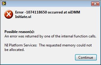
-error with the PXI-4070 107418650 same w/o autorange.
I have a PXI-1033, which includes a PXI-4070 module in slot 5. I use a version of the scanning of switch with DMM - Handshaking.vi but I changed to read a list of fixed scanning and I have replaced the meter of while loop with a fixed reading of 144 samples. After the execution of the present VI about 47 times I get this error:
I am NEITHER-DMM 3.0.4 OR-DAQmx LabView 2101SP1 9.3.0f2 and Vista Business 32-bit slot. I use 4 resistance wire and tried both auto and fixed the range with the same results. Before this loop the related single DMM functions is to read resistance readings 4 son and close the DMM. This seems to loop forever without any problem.
Dozens of times to restart a day gets old fast, any ideas?
-
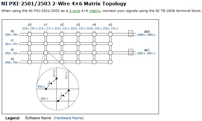
Resistance measurement using PXI2503
Hi, I am looking to understand how PXI-2503 measure resistance of 2-wire matrix 4 * 6.
and I tried several different configuration on my board but I couldn't receive the correct value of the resistance.
Software:
I use the example of LabView8.5 (niSwitch DMM Scanning.vi synchronous switching)
My scan list of entry (c0-> r0) under the switch
between 10000 and resolution 100 m under the DMM
Material:
I tried several set upward,
1. I put a resistor between C0 + AB0 + and r0 + AB0 -; and - c0, r0 - connect to GND, (this configuration gave me some graphics but no resistance)
2. I set the resistance between c0 +, r0 + and AB0 + (they connect) and c0,-r0, AB0 - (but it gives nothing.
my setup is bad? why I could not receive any resistance...
Thanks for any help
Hi Newer104,
The problem may be that the analog bus relay is not closed. Please refer to the following image and note that the ab0 relays must be closed to create a path between the rows/columns and the analog bus.
If I understand correctly, then I recommend placing the resistance between c0 + and c0 - and create the entry list of scan to the following address:
R0-> c0 & r0-> ab0;
Let me know if this solves your problem. Best regards!
Chad Erickson
Switch Product Support Engineer
NOR - USA
-
I use Keithley 2750 DMM to the measures. The device is connected to the computer via the GPIB connection. 7700 two multiplexers are connected to the keithley.
My goal is to get the 4-wire resistance meter in a continuous or intermittent according to a reading of proximity to Labview 8.5 programminghelp. From Keithley 2750 project Style Labview Driver, I had the "continous multi read.vi". But here's the list of 101 to 110 channels, that is to say only 10.
Since uses two 7700 multiplexers, I can get a maximum of 20 values of resistance in trigger.
So What does take to read 20 resistance readings?
Fits the channel list be changed? If Yes to what?
Is there an separate for each 7700 multiplexer address present in the two slots?
I enclose the present common to all 2700, 2750 etc. vi that can measure up to only 10 readings in a single roll.
Don't answer.
Thanks in advance

Concerning
grugh
Hi grugh,
Looking at the context help, I believe that you do not want to 101:110, 201:210
I hope this helps!
-
Strange results of multiplexer ADG608
Hi dear lovers
 ,.
,.I try to use the circuit (within attachments) to switch between the multiple resistance using a multiplexer. Initially, I had different values attached to each channel resistance, but because I was getting very strange and HUGE! results, I've grounded all channels except the first channel and just connect a 120 Ohm resistor. I am able the magnitudes of mega ohms resistance readings and I have no idea how these huge values of resistance are appearing at all. I'm not sure what I'm doing wrong and I really appreciate any help
.We can't directly measure the resistance in an active (powered) circuit. You need to measure the voltage and current at the pertinent points and the Ohm's law to calculate the resistance. The simulators are in this respect as in real circuits.
You must also use voltages and currents that are compatible with the devices in the circuit. With 12 V applied to Y2, you will get 100 ~ my crossing the ADG608 S1 when turned on. I didn't look to the top of the form, but think that it is too common.
Only, I have a few minutes now and cannot establish a tour for you. Connect V1 Y2 through an ammeter. This will allow you to measure the current flowing through the mux. Also to measure the voltage to Y1. Then the resistance switch Rs = (V1 - V (Y1)) /I (V1).
Lynn
-
Identification of audio formats
Once, I thought that the distinctions between the different audio formats were simple, no more. More reading, more confused, I become, so I hope that it is not really necessary to know ALL the details to make smart choices.
"Container formats. concatenated, prefixed with headers ADTS, raw, codecs, ID3 tags, encapsulators, AAC, M4A, MPEG-4, etc.". Maybe I need to know this stuff. What I really want to know, is what format is on my CD. After mount on my desktop, I get two different readings of two different tools. Media-Info says the following (condensed): size 45.0 MB, QuickTime/MPEG Format... 2000format JPEG, Meta info > Type audio, aac, m4as fourCC codec.
Right click on the CD icon produced the following: Format audio CD, capacity 268,4 MB, available 2.5 MB, used 265.9 MB on the disk.
I don't know what 'CD' audio format is. If he has a sense that everybody agrees with, that would be helpful. Also, how is it possible that Media-info indicates the size of the CD is 45.0 MB while the right-click says 265.9 MB?
Yes, it can be very confusing.
-
How do you FF show several lines when it comes to the bookmarks toolbar?
Hello, I'm doing my bookmarks toolbar to display my favicons and multiline text, I tried to find an add-on to help me out, but without success. Please help, I'm losing my mind so to speak...
It could do the job, but he gets negative comments-
https://addons.Mozilla.org/en-us/Firefox/addon/Multirow-Bookmarks-toolbarplus/
For you and a wider audience - I guess you know to keep the bookmarks toolbar on the right side of the page - accessible through the rafters (double arrowheads) at the end of the toolbar.
You can abbreviate the text up nothing via 'Properties' and you can eliminate icons via an add-on of - de-iconise.
-
Is a good PNY CS1211 SSD for my computer?
I own a MacBook Pro and I am wanting to upgrade the HDD with a SSD and I wonder if a PNY CS1211 SSD (480 GB) will be my fast computer. Also, I wonder if I can exchange my SuperDrive with a trolley that can contain a HDD/SSD without voiding my warranty. Please answer; Thank you very much!
I own a 13 "MacBook Pro early 2011 2.3 GHz with 16 GB (2x8GB) DDR3 1600 RAM.
SSD drives... OWC (macsales.com) or Cruical are most recommended. I've been running a Crucial SSD for 2 years without problem. Samsungs have many problems reported here... maybe because of thousands used if the questions are obvious but even Samsung does not claim full compatibility Mac on their Web site.
As for replace the Superdrive by 2nd drive... not really a 'guarantee' issue with a 2011 system that has left no guarantee. But it is not exactly "authorized" by Apple. You might get some resistance of Genius Bar if you take it in to... say... battery or display or the logic of Council's questions. Probably if it was still in warranty the warranty would be void.


Maybe you are looking for
-
Firefox will not reinstall on my computor
Firefox did an overnite update, and after that I couldn't on the internet using Firefox. I deleted and tried to reinstall it, but it keeps just downloading. Sometimes I get an error message of not having mozglue.dll.
-
Unable to connect to the network after upgrade to 9.3.1
I upgraded my iPod Touch 5th gen 9.3.1 and he "lost" the network password. After many attempts to re - enter, I said the iPod 'forget' the network and tried again and again... Same result: "Incorrect password" - which it is not, as I checked directl
-
How much will it cost me to receive calls from landlines or mobile phones?
Should I buy an online number, how much does it cost to receive calls from the fixed network or mobile on my Skype online number?
-
what object to use to write uploaded files to the server?
Hello My question is trivial, but I do not know how to solve. I need to download file *.xml server on my cell phone and write it on the mobile. There are input/output streams to read/write. OK, but what I should write the file I've already read? byte
-
BlackBerry Smartphones Email signature!
Does anyone know how to change the signature which is attached at the end of your emails? I tried what they say to do, but maybe I'm all simply not understand correctly.