6250 OR to analyse the pulses
Hello
I'll use the 6250 OR for my application.
I have 4 channels including 500 US output wide pulse at 4 Hz.
Issues related to the:
1. I would like to taste each channel for 4 seconds. With a sampling frequency of 1 Mhz, it will take a sample of 4 M. Is it possible to acquire so many samples?
2. the card will be able to acquire at least 2 channels at the same time?
3. the card will be able to acquire 4 channels simultaneously?
Thank you
RK
Hello, RK,.
I understand now and Yes you are right in your assumption of sampling rate max for 1 channel. If you increase the number of channels, you reduce the sampling frequency. Here's the formula for this:
Sampling frequency = 1 / (number of channels * 12us)
To reduce this impedance however, you may imploy the buffer of gain unit that I mentioned in my previous post.
Tags: NI Hardware
Similar Questions
-
-Measurement of the pulse width specifies the timeout?
I'm trying to set up a simple project of Signal Express that measure the pulse of two separate signal lines width.
My PCI6224 has two entrances of meter and then run each pulse in the entrance of a meter line, respectively.
The I set up the express project signal attached, which consists of two simultaneously runnings tasks DAQmxAcquire. Each of them is set to measure the pulse for one of the pulse width. I then connect the results for further analysis.
This configuration works very well from time to time. The problem arises when the impulses do not arrive quickly enough and the acquisition of the timeout action. Looks like that has a simple solution - just increase the time-out - but I can't find a single setting around the affects, the time-out! The time-out period is always 10 seconds, regardless of what I do.
Can anyone help?
Thank you.
Hello rothloup,
Unfortunately, there is no option to change the time-out Signal Express for a task entry counter. This has been brought to the attention of our developers.
Reading a DAQmx LabVIEW VI has a time-out node you can specify the time-out period, even in the tasks of meter. I suggest you try to implement your system in LabVIEW (if you can).
Here is a tutorial on how to make PWM in LabVIEW.
http://www.NI.com/Tutorial/2991/en/
See you soon,.
-
How can I count the pulses in a channel?
Hello
I have a channel consisting of 0 and 1 (data comes from a proximity sensor) and I was wondering if there is an easy way to count the events (i.e. pulse) to (Advanced) Tiara? At its simplest, I just need a method to count the number of rising edges in the channel.
A script would be the way to do this? If so, is there any example autour code to demonstrate how to analyse the lines in a channel?
Thank you
PorridgeMan.
Hello!
@Martin: IMHO your aproach can operate, but need not because of input data and the right compares value (10 in your case).
If the input data are not a pure 0-1 step you can get more the a value greater than 10 for a rising edge.
The comparison value depends on the distance of time and the channel values, and it's not easy to calculate in advance.
The other drawback I see is that you need a channel of X, which is not really necessary to solve the problem.I think my code will be more robust (IMHO as I mentioned).
@PorridgeMan: Yes, it's a shame it takes certain steps of DIAdem to solve this common problem.
First: By script is possible, but generally to slow down. My approach is to insert a 0 value at the beginning
a copy of the input channel table and compare it to the input string. If a value is less than 0,5 (half of you maximum values)
and the other is higher I put a 1 0 otherwise in a result string. Even in more complicated cases, the comparison value could
be calculated or alienated by a moving average.
Here is the code:
Option Explicit

' Copy data
Call ChnCalculate("Ch(""[1]/Dif"")=Ch(""[1]/Pulses"")")
' Insert one 0 at the beginning
Call DataBlInsertVal("[1]/Dif",1,1,0,0)
' Compare and convert result to 1 or 0
Call ChnCalculate("Ch(""[1]/Result"") = IIf((Ch(""[1]/Pulses"") < 0.5) And (Ch(""[1]/Dif"") > 0.5), 1, 0)")
' Sum is result
Call MsgBox(Cch("[1]/Result",4))
Hope this helps
Matthias
-
at the same time production and measuring the pulse
Hello everyone,
I'm generates a pulse for specific time. Now, I want to measure within the same daq card. I've done Vi for him but he has an error. I have USB daq-6343. I enclose my Vi here.
The problem is I am able to get pulses generated at PIN 6 PFI but reading Vi watch time-out error.
I plugged the wire between PFI 1 pin and PFI 6 pins on the DAQ card.
So please suggest me what to do to eliminate this error.
Thanks & best regards,
I just looked at your original vi, I had looked only at the most distant (corrected) a previously. I don't see a good reason to read timeout error you have immediately. Record of an error timeout on your attempt reading suggests that the code was executed without error so far, including the beginning of the generation of pulses. That would leave wondering on physical cable connection or possibly some undesirable side effects caused by your cleanup code when you three States a PFI lines.
The other issue was my suggestion to leave DAQmx Timing.vi outside of the configuration string entirely for cases like this where you only want to build a single pulse. To be honest, it's a habit & practice I adopted a long time ago. I thought one of the reasons was that the finished pulse trains required a minimum of 2 samples. A bit of test code showed me that it isn't true, if my memory tells me there was a time when it * used * to be true. I don't remember if I have errors or if the task has chosen to generate 2 pulses with just a warning, or something. I just remember that, while he was working on a module that was supposed to be able to produce any number of pulses from 1 to N, I found that I wasn't actually able to support the case of 1 pulse by asking just 1 sample over sample mode.
* Anyway *, the other reason to avoid sampling over for a single pulse mode is that in the past, this would consume actually 2 counters on DAQ cards. Generated the pulse (s) while the other was a help that triggered the first to control the number of generated pulses. It was unnecessary as you could * also * generate a single pulse leaving the DAQmx Timing.vi out of the config, a method that used only 1 meter.
X-series cards (like yours) don't consume over 2 programmable counters of the user to generate finite pulse trains, so the lesson I learned a long time ago and was trying to convey is perhaps not so important in your case. I recommend it even if you know that you will always generate a single pulse, simply because he considered the standard way to generate a single pulse (as seen in examples of navigation).
-Kevin P
-
VI to convert input signals NI 9402 in a RPM value, based on the frequency of the pulses
Hello
I'm looking for a VI convert an input signal NI 9402 in a RPM value, based on the frequency of the pulses. Is there such a thing that exists in the library of national instruments?
I run LAbview 2014 integrated control and monitoring on on a cRIO 9802 high performance integrated system with NEITHER 9402, 4 channels, 50 LV, LV TTL Module input/output digital, ultra high speed digital i/o for the cRIO module.
Any help would be greatly appreciated.
The easiest way is to use the FPGA to get the time between the edges of your pulse increase (shift registers to maintain the current situation and the time will be necessary). This will give you the period. If it's a single pulse per turn, then the number of laps is just 60/T, where T is the time in seconds.
-
Measure the frequency of the pulses PXI-6624
Hello. I work with a PXI-6624 and am interested to make measurements of pulsed frequency for frequency and duty cycle on its inputs using DAQmx.
When I go to create the virtual channel, however, I have error-200431:
"Physical channel selected does not support the type of measure required by the virtual channel you create."
' Asked the value: pulse frequency.
«You can select: frequency, period, pulse width, period of Semi, separation of the two edges, Position:...» »
Is this card really not capable of doing these measures of pulse frequency?
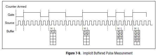
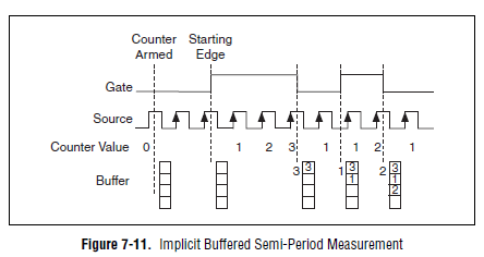
Yes, the "Pulse" (not to be confused with "Pulse Width") measure was introduced with STC3 of OR including CompactDAQ and X series devices.
Measuring the pulse:
However, you should always be able to measure the frequency and the duty cycle on your card with a half measure:
The half measure:
The images are in the X Series user manual.
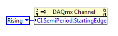
The difference between these two modes boils down to how the data is stored and implemented in buffer on the map - with the period semi method that the material does not distinguish between high and low samples and puts everything in a single buffer. However, if you start the meter on the song (see below the node property), then you would know the order of low and high samples in software, and are easy enough to calculate cycle frequency and the duty of this.
Best regards
-
Salvation;
Here is the solution for your problem.
The cause is that "Gen dig Pulse Train-Finite" uses Ctr0 both Ctr1.
Please refer to:
"When you do a finite pulse train generation, a counter generates pulse train, and the other counter generates an impulse that acts as a barrier to the first counter. If you change the pulse train to generate continuously or
only generate a pulse, you can run two tasks of meter at the same time without error. »
http://digital.NI.com/public.nsf/allkb/04BEDD9E9E91ED3486256D180048116D
I used Ctr0 and Ctr2, jumping Ctr1 as it is reserved by "" Gen dig Pulse Train-Finite ". I works very well.
Kizito.
-
Count the number of 1 is present in digital waveforms obtained by converting the pulse signals.
Hello
I use Analogtodigital.Vi to convert the pulse of the sequences in digital.signals.I am able to get the representation of digital waveforms of impulses.
But how to count the number of 1 is present in the converted digital waveform. I want to count the number of 1 is present in the digital waveform converted.
Thanks in advance.
Have you tried the block scheme of similar to the Digital.vi of opening?
It creates an array 2D uncompressed 1 and 0, which is the binary 16 bits A/D conversion of each element in the array Y of the input waveform. You can use the DWDT digital Array.vi Boolean to convert a 2D Boolean table. Then convert Boolean values to 1.0 and summarize the array of integers. The sum must be the number of 1 bits in the digital waveforms.
Lynn
Note: The VI attached is saved in version 8.6. When I have it saved for the previous Version a warning was generated about the possible differences in the versions. Let me know if it doesn't work, and you are using which version of LV.
-
How to count the pulses using RIO (FPGA)
Hello
I want to use RIO (FPGA) for counting the pulses produced by a sensor,
but I don't know how to program. can someone help me.
Thanks in advance
CAIX wrote:
Hello
I want to use RIO (FPGA) for counting the pulses produced by a sensor,
but I don't know how to program. can someone help me.
Thanks in advance
Search for example for 'Meter of RIO' finder. There are dozens of examples that should help you.
-
Can we all define the difference of hard and soft analysis the analysis
Can we all define the difference of hard and soft analysis the analysis coming in SQL tuning advisor and ADDM recommendations.
To improve the same needs to be done. Please advise on the same.
Thank you
What is analysis?
-> any query SQL under validation goes to the shared pool
Validation: check the syntax, semantic check, etc...
Hard analysis SQL going for below in the shared pool
Syntax
Semantics
Transformation of the query
Optimization
Create an executable
E/S
soft analysis (reduced time spent by jumping the redundant task)
Transformation of the query
Optimization
Create an executable
E/S
Thank you.
-
How to analyse the core dump generated by the user application
My user application developed for ESXi 5.5 occasionally generates signal SIGSEGV, causing in turn core dump generated.
I used this command to enable the generation of core dump in the directory/var/core.
/ sbin/vsish EI configuration/userworld/global/coreDumpEnabled 1
After dump generated, I tried using esxcfg-dumppart to extract the logs of information, according to this link http://kb.vmware.com/selfservice/microsites/search.do?language=en_US & cmd = displayKC & externalId = 1006796
But it seems that this tool is intended only to analyze the kernel image.
/ var/core # esxcfg - dumppart - L appdump - zdump.000
Error running command. Failed to retrieve the log. Cannot find a valid dump VMKernel file. Partition of discharge can be uninitialized.
Is it possible to analyse the core dump generated by application "userland" in ESXi 5.
Thank you
Arun
Hi arunkrish,
OK, this tool (esxcfg-dumppart) is exclusively for the extraction of a file readable to vmkerneltext - zdumps. The recommended method for the guest operating system dumps review is vmss2core which gives you the news crashdump desired in a format readable by the debugger for the OS in question asked. As I understand it, the * zdump.000, * zdump.001, etc., are questions of trapping in the VM (i.e. rather than the GS) level.
I think that only VMware support can read these basic gos/vmx dumps that you are trying to review (I hope I'm wrong). However, you can try your luck opening them in a debugger pro such as IDA Pro (speculation). They have a free trial version.
-
Inaccurate statistics in application of the pulse
In particular, the heads of the displayed region seem to be off when I joined to my DataGrid with the application of pulses. All regions have the same number of entries (297779) in Pulse, if I ask the regions with applications I can see the exact number of each region (for example 0.11, 182715, 4981, 39845, 9958, 5, 4858, 204217, 35, 1). I can verify that these counts are correct since I am loading the records in a database. My datagrid is composed of three members of server with two locators. All regions are partitioned. Also, I am able to see all members with precision in the pulse, it seems to be configured correctly. Any idea on this?
Thank you
Tom
Tom,
There are a number of impulse of bugs regarding the data displayed incorrectly. What version do you use? The last patch available pulse is 7.0.0.1. If you're already on it, so you wait 7.0.1 which should be available in a week or two.
-Jens
-
Is this possible with LR5 to export the EXIF of every photo album (or albums) to an Excel file? My goal is to analyse the focal length I use most. It could be used for various other analysis also
Therefore change one of your columns in the filter bar to display the focus distance.

-
Hai all the...
I'm using the port Usb-6009 meter to measure the engine for each 0.1 s and save it in the file lvm. Aquistion and and logging of data at the initial stage say 10 minutes generated pulse is acurate and data is stored for each 0.1 s, after the 10th minute acquistion speed and recording speed goes slow and instead of data for each 0.1 s acquisition it measures for 0.12,0.14,0.16, and... 0.2, 0.3 S... and stores. For this reason, I'm bored n number of impulses and I could not provide appropriate time resolution.
After analysis, I found that the acquisition depends on material used and the system used.
My System Configuration is
Intel core 2 Duo processor
2.67 GHz, 1 GB of Ram
anyone can suggest a solution for the above problem, is there another way to measure signals without loss or delay. ?
Check the attachment. You can get an idea.
-
niScope acquisition surveyed EX: simple taking the pulse?
I built an application scope of rather useful digital storage around the Acquisition of respondents that NEITHER furniture.
My problem is that I can't capture a single pulse by a lamp circuit. The vi always re triggers the worst
time and erases the original trace. Y at - it a simple way to implement a unique trace as the soft Front mode
Application of Panel?
Koutcheens
Dan.
Unfortunately, I'm doing rather poorly on the logic statements. If it wasn't for the fact that LabView is so user friendly, I couldn't
program at all. Since LV 5.1 I used the method "institutionalised blind squirrell finds a nut" with never decrease
results. I've attached a screenshot of the best that I could understand your explanation. Of course, I missed something.
Koutcheens

Maybe you are looking for
-
Windows Live Error 0x800CCC0E, socket 10013 error I use Windows Live mail for months and suddenly can not receive or by e-mail. I'm getting Error 0x800CCC0E, socket 10013 error ID. I don't think that all the parameters have been changed recently.
-
Random BSOD - critical process on my vaio flip error
Hi all! I got my flip (model: SVF13N25CDB) for about 6 months now and about 1 month ago I started having BSOD at random. They either stat that it is because of 'mistake of critical process' or 'core data entry error ". They may not the case for day
-
My application requires gps permissions in order to run. How can I check to see if the application has permissions for gps and prompts the user to select Yes if the app hasn't already have this permission programmatically? Is this possible?
-
OfficeJet 4500 Wireless: change the network key
Try to change the key to network on my printer, it asks password wpa but my key is in numbers. When I press on the keys to encrypt, letter s came, how to change screen to get the numbers appear.
-
Error on blue screen after connecting USB blackBerry Smartphones
Hello, I have a new 8100. Everything is great, everything works, but the problem appeared after I installed the software and I have connected the mobile to the computer by USB... the blue screen error Windows Vista appeared, thenAfter the automatic r