6602: rising edge capture hardware interruption
I have this input signal:

I have to do something about rising as soon as possible.
My idea is to receive a break hw of the Board of Directors and write a Sri soubroutine.
I read about the callback function, so I write code.
But when I call:
DAQmxErrChk (DAQmxCfgChangeDetectionTiming (udpTaskHandle,
Dev1/Ctr0"."
Dev1/Ctr0"."
DAQmx_Val_ContSamps,
1)) ;
I have an error for the ctr0, it seems that I can use the port0 onli.
Now... is my question on port0 a thread of software that continually read the value of the pins?
Or is it still a material interruption?
I think a software thread has a large latency for me, at this point useless 6602 jury,
I could read the signal on LPT port standard.
Thanks for the reply.
If you do not want to read the value of the counter, try replacing the code read what follows:
You currently ask 1000 samples to read so the Read function is blocked until 1000 samples are available. Reading is not necessary if all you want to do is raise the event to do something else (which is what it sounded like messages earlier).
Let me know how it goes!
Best regards
Tags: NI Hardware
Similar Questions
-
Operating system: Windows XP
Hardware: PCI 6259
Terminals used: PFI0 and PFI2
Counters used: Ctr0 and Ctr1
IM developing an application for the acquisition of data where timed loop synchronization source comes from my PFI2 (using the string A of an encoder). IM basically trying to acquire data based on the number of ticks from my encoder. For the synchronization source, I use counter 1 to capture the rising edge and have the loop time-acquisition of data. At the same time, Im using the counter 0 to count the number of rising edges so I know exactly in what tick data was acquired. PFI0 and PFI2 are connect to channel A of the encoder.
Questions:
Timed loop acquires data at each tick, because when I discover the data (text) file is missing count of my encoder value. Is it because there is a limitation on the Windows operating system? I used a noculars to measure the frequency at the maximum rotation of the channel encoder and 6,757 kHz. All solutions?
Also, is there anyway I can route the source channel internally an encoder to generate synchronization source instead of using another counter? I have attached my VI.
Hello
All the samples that you acquire will be read by LabVIEW in a sequential manner. Figure 4-21 on the M-series on page 80 (4-34) shows that you will acquire all the samples you request all channels that you enjoy in sequentially.
-
Satellite Pro L300 - no video capture hardware
Hi all, I'm new to the Forum so apologize me if this question has already been answered previously.
I am trying to connect a USB Webcam to my Satellite Pro L300-153. Wizard installs the webcam and updates the drivers etc, but trying to work webcam a mistake happens "* webcam works not properly no video capture hardware detected."
Can someone advise please. Thanks for your help.
Hey Buddy,
In my opinion, you must contact the manufacturing of this USB webcam. I put t know which model you have, etc. and there it s a Toshiba forum so I think that no one can tell you if it s associated with driver problem or camera itself.
But I put t understand why do you use an external webcam. AFAIK all Satellite L300 are equipped with internal webcam
-
Hello
I use a PXI-6251 data acquisition card.
On this one, I trigger a final signal on analog output.
I would like to launch a rising edge on the terminal where the analog output task is really run.
Actually I provoq a trigger output when the analog task is to start.
Is this possible?
Thanks for the reply.
Concerning
=========================
Hello
I has a PXI-6251
On this one I generated the United Nations end analog signal.
I wish every a rising edge on a PFIX output when the build task to start. Only then this output falls to 0 when the task is stopped...
Possible is it?
Thanks for your replies.
Hello __KB__,
I think you should start from this example: https://decibel.ni.com/content/docs/DOC-5374
Then, you have to adapt in order to define a model that generates a high level as soon as starts the analog task and which generates a low level at the end of the acquisition of finishes.
In order to know which digital line corresponds with your PFI line, you will need to look at the documentation of the PXI-6251 (http://www.ni.com/pdf/manuals/371291h.pdf, page 14). You can also get information from MAX.
Kind regards
-
Work2 House part2 - rising edge
I am trying to modify the code to use a rising edge, but if I do it just doesn't quite work. Set a breakpoint on the earpiece never hits so it's as if the trigger is never pulled.
Also when it does not work I tried a TRIGGER_HIGH_LEVEL. He crashed to the virtual machine.
Hmmm... You use the GPIOSwitchTest project?
It worked by using TRIGGER_BOTH_EDGES?
If so, first change the code for the following valueChanged method:
    public void valueChanged(PinEvent event) {
        GPIOPin pin = (GPIOPin) event.getPeripheral();

            if (pin == switchPin) {
                if (event.getValue() == true) {
                        System.out.println(" true");
                } else {
                        System.out.println(" false");
                }

            }
    }
So if you change the GPIOPinConfig to TRIGGER_BOTH_EDGES to TRIGGER_RISING_EDGE, you will see that real messages. See this post to explain why the change of the code is necessary.
As to why TRIGGER_HIGH_LEVEL "crash the virtual machine" - I think what you meant was, he threw an exception - specifically and IllegalArgumentException.
I'll add this as a note, but in the documentation of the Raspberry Pi in the GPIO section, it says: "the triggering modes
TRIGGER_HIGH_LEVEL,TRIGGER_LOW_LEVEL, andTRIGGER_BOTH_LEVELSare not supported on the Raspberry Pi.»Tom
-
County rising edge specifier "10280" generates the error "-200220"»
Hello
I use the box USB-6008 with PFI 0 configured as a counter edge. Everything works fine when I use it to count the edges fall with the "10171" specifier, but .vi DAQmxBase Create Channel (CI-County edges) generates the above error if I simply replaces "10171" with "10280. This specifier is not recognized by the device?
Thank you
Tyler
Hey Tyler,
I've dug into this and found an internal report, and apparently only a falling edge can be used as a trigger of edge with patches of meter. The other problem is that, even if you can use both, there is that a single input pin for this meter and edge only one type can be detected at the time. The only solution I see would be to try to find a device with several counters, or take an another 6008 and use it to count the edges of the second switch.
-
Working with interrupts (programming) software/hardware
Hello
I'm trying to manipulate the position of the mouse with a program that I wrote using hardware and software interrupts, but it seems that the cmd cannot work with these functions.
Is it possible that the cmd is unable to work with the program who are trying to manipulate the keyboard and mouse?
programs that try to overwrite the software/hardware interruptions?
y at - it a why to make it work?
P.S
I ran this program with DOSBox and it worked.
Thank you.
Windows 32-bit 10
Hello
You may need to ask the question here:
https://social.msdn.Microsoft.com/forums/en-us/home?Forum=scripting
Kind regards
-
hardware video capture... my web cam worked fine utill today.
From today I can not get my web cam to work. I deleted and reloaded but didn't achieve the same result "no video capture hardware" how to fix this? the program loads ok, but the message no video capture always happens... can someone give advice... Thank you
Hello.
Thanks for your help... Funny, that I remembered, I just did a defrag and then worked on a hunch made again last night and my cam lol sorry if I confused anyone. but I will keep the pages that has been cited just in case need
Thanks again
Maurice -
Triggered Cameralink Acquisition only capture half of the executives
Hi all
I am aware of this page- http://digital.ni.com/public.nsf/allkb/6FFA526966E2D29386257AA80054730A
He describes my problem, but I can't find a good solution.
I have four cameras that should be triggered at the same time (they cannot be free running!)... If I only to trigger the cameras, and allow acquisition cards to run without a trigger, I find myself occasionally lack of executives at increasingly higher rates. To 100 fps I have lost about 40 percent of the data, but about 50 fps I capture all the data correctly.
When I trigger both the image grabber cards (1430 years) with cameras, I seem to always miss all the other images.
I tried to trigger the cameras on a rising edge and the cards on the falling edge, but no matter what I myself only to collect half of the frameworks I expect to collect over a period of time.
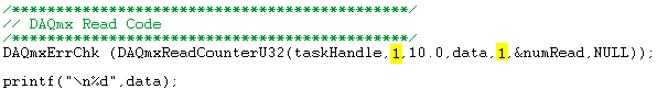
Here is a snippet of code that I use for the acquisition is something urgent?
Thanks for your suggestions!
-MK
Triggering the camera still works best, in my opinion.
You're doing an acquisition in the buffer? The code you posted looks that you use just Grab, that does not use a buffer. With an acquisition in the memory buffer and outbreak of the camera, you should not have problems.
Bruce
-
How can I use two counters to capture a pulse ttl for a specified time
Configuration: Card counting 6062 PCI w / BNC 2121 Board running under LV 9.0 PerkinElmer Avanlance Photodiode (SPCM-AQRH-13)
I searched through the forums and fell on the theme of framing an image while collecting signals from a source for a specified time.
The example in terms of falkpl in 2005:
"
Dismal Hello,
I'll try to point you in the right
direction to start coding the application, but do not forget my
suggestions have to be modified to your specific request.For
the task output redeclenchables finished meter you need to
your counter seconds in this application, I suggest to take a look
in the Finder example in LabVIEW ('Help' are examples) and less
DAQmx hardware entry & exit"" generating digital impulses. Here,
you will find some Gen dig Pulse - Retriggerable.vi. You can use this for
Create your door 4 pulses ms it's over (not a pulse train) and
redeclenchables (for each time you go to the next step.In
regards to the configuration of the first counter, there are several things to
consider, and I can offer initial help to get set up. You
in-house allows to route internal CTR1 (4ms of pulse) output for your CTR0
Door to measure only during the time. Here are additional
Info to do this in LabVIEW. The source of your task of edges ABOVE County
will be the TTL signal you are measuring and counting. It comes
on the PFI line that corresponds with CTR0 Source.When
you make a measurement finished with CTR0, you will take only heads while
the door is high and your source has a rising edge. You can set the
measure over to start on a trigger, which is not clear in this
for example, that you have identified. Since you know that you have a finished 4ms pulse
time to measure, you can set the duration of your measure
as a result.I found this
Forum which may help some, but the coding is
textual. I hope this can give you a good starting point for
programming. -
Hardware timed CI/CO, operation of PCI, I / AO with specific execution order
Hi all
I work with a USB-6361 NI data acquisition hardware and I'm writing a LabView 2011 program which sends a signal to my output device and reads several values of various measuring devices. I have a ramp voltage signal (in a table format) and I need to sequentially send the elements of this array on my AO device with very precise timing (ideally timed material). As soon as the value is written to the device of the AO, I need my tasks HERE and CI to record all available data and my task to send a single impulse before the next array element is sent to the device AO. All this needs very precisely timed such that if I perform a measurement on 1000 points in my table of ramp with a timing of 1000 Hz, the program will have exactly 1 sec. to run (less overloading caused in initialization and closing tasks) and produce a table of data consisting of 1000 steps of AI and CI. I had initially tried to achieve this by using a structure of sequence within a timed loop software, but because I won't get into multiple channels of Amnesty International and CI and tables of data, this has proved to be excessively slow. The other danger that I fear I could run is the case in which the LabView program runs more slowly than the process of acquisition data itself, thus causing data to write to the buffer and the measures being lost.
I didn't spend a lot of time working with the procedures, timing and synchronization, so I apologize if this is a rather naïve question - I'm having trouble reconciling restrict them inherent software and order of execution with the hardware timing. What is the best way to solve this problem? I can only think of two reasonable approaches to the problem:
(1) should I try to trigger my CI tasks and HAVE run on the completion of the task of the AO (and if so, how)?
(2) I have the CI and tasks run on a separate clock with a start delay initial light as to compensate for these tasks if they occur reliable after that each value AO is sent to my device?
Finally, I build an identical for a real-time embedded controller program of SMU-8100. The approach will be different in this case?
Thanks in advance for your answer.
I can give you an overview of the steps you'll need, but be ready to spend experiment a little time and some of these individual pieces of troubleshooting before you put them all together.
First of all, a X-series 63xx allows all you need to accomplish a very precise synchronization in hardware. When you then switch to a real-time controller, you must include an X-series device in the chassis to maintain this capacity of equipment.
Second, 1 kHz is not yet a challenge to LabVIEW to catch up with your hardware, even with powered lower RT controller. You just need to program the DAQmx tasks to let the hardware & driver do most of the work.
1. I would dedicate a counter of the 6361 to generate the clock shared for other DAQmx tasks. I tend to create a clock and operating cycle of 90-95% for this type of application of stimulus / response to the response time & maximum stabilization. Generate the stimulus at the cutting edge of the clock and gain response data on the edge of leak - before the next sample of stimulus. Call it the task of the clock.
2 set up a buffered AO task that uses the output of clock as the sample clock. Configure the polarity to be sensitive to the cutting edge (usually, this will be a rising edge). Start the task AO * before * starting the task of the clock.
3 configure tasks HERE and CI to use the output of clock as their clocks in the sample. Configure the polarity to be sensitive at the trailing edge. Start tasks I and CI * before * starting the task of the clock.
4. the output pulse should be a task of meter output, configured to generate a single pulse redeclenchables. Configure it to use the leading edge of the clock as the trigger signal output. Set the time of 'low' and the 'initial period' to equal precision<1 msec="" delay="" you="" want="" to="" make="" sure="" that="" you="" get="" the="" same="" timing="" on="" every="" trigger.="" be="" sure="" the="" high="" time="" allows="" the="" full="" pulse="" to="" fit="" within your="" clock="">
5 examine the "producer-consumer" model so that you can separate your data from your CQI data processing. You should stream to file continuous rather than it accumulates in large networks. Write speed of file can be unpredictable, this is why access to the file must be in a separate loop that acts as a data consumer that the loop of CQI data produced. When you spend real time, assign a lower priority in the process of writing file.
-Kevin P
-
Capture a sample only after analog triggering on a PXI4461 in Labview SignalExpress
-Repost on LabView forum where this thread belongs.
Hello
I capture two waveforms (external excitations) with my PXI446, one on each HAVE. I use one of them as an analog trigger (rising edge @ some tension), let's say AI0. I need the value of AI1 on time (or a fixed number of dt later) when the trigger occurs. I need just a sample.
(I almost use the 4461 as sample & hold circuit with AI1 as an input signal and the AI0 as the sign of "sample".)
Currently, I use a "subset and resample" step with a very small dt and it seems that it works, but I don't like.
The above procedure is in a conditional loop that collects 100 of these samples (acquire signals triggers 100 times) and produces a statistic of this set (using the step statistics).
Is there a better way to do it?
Thank you
Aleksandar Andreski
Hi Peter,.
Thanks for your reply.
I also think the same: do better in LV, rather than SE - LV. I tried the "subset and resample" function before, but as you say, that it cannot be made to select only a single sample. Moreover, the overhead IS are more bigger than in LV and so it slows down other parts of the measure that I have (e.g. a conditional loop).
I'll probably do a task of LV.
BTW, if I use LabView Realtime, can he run said fastest loops?
Greetings,
Aleksandar -
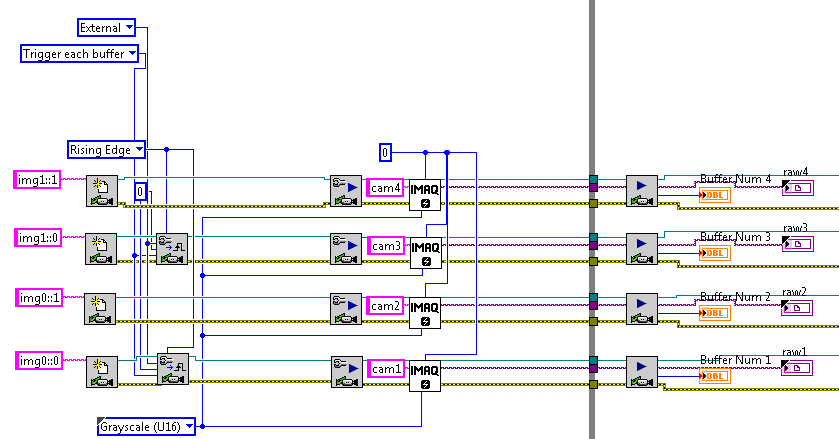
Capture camera IMAQ via DAQmx trigger operation
Hi all
I thought I could re - this poster in this forum to see if I get more ideas!
I work with a PCIe-1427 card connected by link to a camera (SUI Goodrich) and also using a card PCI-6731 to which I attached a connection block M SCC-68 series.
I managed to write code to control the .avi capture the camera and write separate code to control the lighting of optical switch connected to the SCC-68.
The two lines of the optical switch Relay different info and I will in turn present this information to the camera for analysis. Ideally, I'd like to trigger the acquisition of the capture of the camera with the optical switching so that each image contains information of a single channel only, but I still fell in the integration of the operation of DAQmx meter with IMAQ camera code.

Is this possible? I see 1 previous post by using a RTSI cable can I connect the two devices together (or alternatively use the DAQmx to produce a trigger on the digital). Can someone offer information or an example on how to route signals via the RTSI to IMAQ DAQmx? Also do I tuned regarding the generation of pulses to the switch that allows signals to pass through RTSI?
I find it by running my camera and counter code in vi even both will work (not in sync)-if I connect the RTSI and select the camera settings to accept the RTSI triggers, if it was a simple solution?
I would greatly appreciate any ideas you may have. my time runs out very quickly and is really distressing.

Sincere greetings and thanks,
Miika
Miika salvation,
If I understand what you try to do in VI you attached, you want the output of the counter of the task DAQ to serve the trig by buffer task it IMAQ via RTSI.
To do this, use the property node of channel DAQmx to configure the output terminal of the impulse to be RTSI 0:
Select property > counter output > Pulse > output terminal
B. change the node property to write.
C. create a constant and select/Dev1/RTSI0
On your IMAQ configure Trigger VI, RTSI value as type, set to 0 the number of line, set the action to trigger each buffer and set the polarity to rising edge.
Oh yes, make sure to connect the RTSI cable for two cards. I forgot that before and felt really stupid later.
-Jeff
-
PCI6120-acquire an analogue signal on each edge of a digital signal
Hello
I have the card PCI-6120 and Labview 7.1.
I have a digital signal of the encoder. Am interested in buying an analog voltage on each rising edge of the digital signal. In addition, I have another digital signal (index) between which I wish to make the acquisition.
I tried several options. But I can't get on the digital dashboard via the hardware. Please help urgently. Alternative, I migrated to the acquisitions acquisition high speed analog and two digital channels and deteting change in software programming and then find the analog voltage. Which is heavy and inefficient.
Kindly guide correct programming technique.
Concerning
Marie-Hélène
Hi, Maud.
Thanks for the update and I hope that your well today.
Sorry for the delay but it was the Easter holidays!
Thank you for your congratulations.
I put your sampling frequency at the maximum rate of the clock source (encoder). The DAQmx driver uses the sampling frequency (and the number of samples per channel) information to perform various calculations and set sizes for the buffer.
If you set it too high, nothing will happen-guests still just on each edge of the unit receive. If you set it too low, your stamp could be too small and you may lose data.
Hope this helps,
-
Hello, I am designing a detector of negative edge using a d-type flip flop that gets a signal from two cascaded from the binary counters that are used to reset when the desired value is reached. The design should include a frequency of window, but I do not know how to implement it. I tried to implement but I could, but I don't know if it works. No idea?
Hello, thanks for the answer
Sorry, but I guess I'm not smart enough to digest your description.
I have-
We must build counter for 0.51 with reset - you did.
We must build flipflop (FF) with triggers on falling edge.
the possible solutions are-
-You can use rising edge FF if you could reverse the trigger signal.
Learn about the different types of FF, some of them work on edges falling
with it will be useful
Good luckMichael
Maybe you are looking for
-
Is it possible to copy an iMovie project, and I therefore two versions to work with?
I have an iMovie project finished with background music. I would like to have two versions - one with background music - and one without having to redo the entire film. I see "duplicate" as an option in the drop-down menu editing, but it is not an op
-
Satellite 1730CDT, DVD burner replacement
Hellois it possible to replace the CD with a DVD burner drive?This laptop does "cable select"?Guenter.
-
Service Pack 3 has not finished click OK to undo the changes that have been made
Internet Exolorer 8, service Pack2 installed. Tent to download and install service pack 3 again, Error Codes: several years ago Not enough free space. Free storage, Total currently 6.06 GB GB 32.3. HP pavilion 551w. Error codes: 11/10/09 OX8007064
-
OfficeJet 8620: Officejet 8620 screen
Hello The 8600 OfficeJet, who I am today his retirement because the automatic document feeder died, had a nice feature that allows you to rotate the display screen is easier to see from above. My question is: is it possible with the OfficeJet 8620? I
-
Hello! When I put the border in one of my extended fields it works very well with the model 8520 but it sets the color in black with the 9000. Anyone know why? Both of my mobile run version 4.6 (for 9000 4.6.0 and 4.6.1 for the 8520) public MyButton(