negative edge trigger
Hello, I am designing a detector of negative edge using a d-type flip flop that gets a signal from two cascaded from the binary counters that are used to reset when the desired value is reached. The design should include a frequency of window, but I do not know how to implement it. I tried to implement but I could, but I don't know if it works. No idea?
Hello, thanks for the answer
Sorry, but I guess I'm not smart enough to digest your description.
I have-
We must build counter for 0.51 with reset - you did.
We must build flipflop (FF) with triggers on falling edge.
the possible solutions are-
-You can use rising edge FF if you could reverse the trigger signal.
Learn about the different types of FF, some of them work on edges falling
with it will be useful
Good luck
Michael
Tags: NI Software
Similar Questions
-
the analog inputs with digital edge trigger
I am currently triggering a readout with a digital trigger using a 0 - 5v as the digital source encoder. I am running LV 8.2.1 DAQmx 9.0 and a PCI-6259. I use a VI I wrote and which is very similar to 'Acq & chart voltage-Ext Clk.vi', and using the one-pulse encoder connected to PFI8 as the clock source for the sample clock vi. The only major difference is using the channel of the Z-trigger as a software reset inside the While loop with the DAQmx reading. Currently, the sample clock doesn't allow that either read the lower edge or an increase of PFI8, so I get a sample by one-pulse.
I need to double the rate of analog playback for a given tree rpm and encode them, so I need to read on the fronts and edges of the one-pulse encoder. The sample clock can be reconfigured for the detection of changes and still read the PFI8 port to increase and decrease as inputs of physical channel, or do I have to configure detection of modification of the task/digital input for a single line and use the "ChangeDetectionEvent" as the source for the sample clock HAVE? Detection of Timing/change DAQmx can still use the signal in PFI8, or should I use DI ports, and which ports are DI should I use?
Thanks in advance!
In fact P0.8 is. I was looking at the pinout for the 6251, no 6259. Sorry about that.
-
Is it possible to trigger an Animation of edge with say a reversal, a click or a deployment?
You can control with a scrolling parallax effect, so it shouldn't be completely strange to control objects Edge animate with various States or...?
Yes > add the action to the Edge host file/animation itself.
-
Animation of edge trigger on the loading of the page
I use several Animations of edge in a DPS document I created. When I opened the book, all of the animation start playing at the same time.
Is there a way to trigger the animation starts when the user turns the page on animation?
The value of the retard.125 seconds.
-
Can I use 1 PFI on 5133 as outside edge trigger
All vi for the config, I can use the trigger. Thank you.
-
Single channel match trigger speed model vs onset of edge on the PXI-6562
I think that my question boils down to this: what function does the edge of trigger plan that is not provided by the model match trigger?
As far as I know, the only differnece on the PXI-6562 is the edge trigger has its own pins dedicated (PFI pins and pins RSTI) to detect a trigger, while the model match trigger detects a rising edge or falling on a regular input pin.
Is there a difference in performance (for example, the time to rearm)?
Are both triggers synchronous types with the sample for dynamic acquisition clock?
On my application:
I acquire a signal off a SPI bus, triggering the CS line. I start to acquire data when the CS line going down and stops when the CS line is high. As I acquire data CS on a regular supply, it seems logical trigger on a pattern for this channel only match. I'm curious to know if there is any advantage to connect a PFI PIN to my CS of entry so that I can start using digital edge type.
Thanks in advance,
Arthur
Arthur,
There is no difference with regard to performance using a digital camera compared to a type of pattern match trigger. Specifications for rearm time reference to the trigger type (Start, reference, etc.) in the samples to rearm, and there is no difference with the performance when you use a digital advantage over a line/PFI line Trigger and a correspondence to the model used on the input signal. Change the source of the trigger itself will not change the performance of the material that occurs after the trigger is received. This behavior to sync with the clocks of acquisition regardless of the input source. We're just looking at different sources for the jury to look for a given trigger.
-
I created a program that reads analog data and draw a waveform, but I need to stop the program when the voltage drops to a certain tension. When I tried the analog edge trigger it showed the error in the subject:
Reason: The requested value is not supported for this property value. The value of the property may be invalid because it is in conflict with another property.
Property: Trig startup type
Requested value: analog edge
You can select: Digital Edge, no
I understand what the analog trigger is not available for my DAQmx version, without again getting equiptment, can I use a trigger to stop reading data at a specific voltage?
How to start and stop a similar read digital triggering?
Thanks in advance!
Ah! Well, then the Boolean value of status would be connected to the State of the thread of the unbundled error, Boolean stop to the stop button and the Boolean value to the right would be the stop for loop itself... so something like this (see image). This is an excerpt from LabVIEW 2014, so it can not easily fall in your version, but I hope it's clear enough on how you can wire it to the top.
-
Redeclenchables buffered count task of edge
Hi all
I worked on 'Buffered Retriggerable counting task dashboard' on a single window input channel, let me describe what I want to achieve:
Create a CI to count the rising edges finished with the (for example external sample clock Dev1/di/SampleClock) at some rate of sampling and CI.edge.Term together in a PFI which is wired to another channel of digital input. In addition, I would like to define "start redeclenchables trigger" for this CI by another PFI line.
It turns out that I can put only 'arms start trigger' on this channel of entry of the counter, instead of "start trigger" since the 200452 error: attribute not supported in the context of task showed up at the beginning of digital edge trigger configuration. It seems that I can put only 'start redeclenchables trigger' on output special counter and use two counters to reach above, but I was wondering if there is a way to accomplish through single window. Any suggestion is appreciated.
Set the THIS ongoing task - it won't take samples when the task finished di which is actually the same thing as having a task over redeclenchables CI triggered.
If you want the count to reset each trigger, you could configure the entry as a Reset counter line well trigger.
Best regards
-
niHSDIO dynamic generation and Acquisition using LV configure Trigger VI
Hello!
My experience is limited within the environment of digital programming; Nevertheless, I have worked on this problem for a few days and would appreciate some comments if possible.
I am trying simply to generate and acquire a duty cycle of 50% of 8 MHz TTL pulse train on a PIN DIO of the PCI-6541 and acquire back from the signal on another axis of DIO. I have a connector corresponding to the embedded 6541 VHDCI connector which of course the generation and acquisition DIO welded pins to provide a loopback effect.
In short, I use the niHSDIO configure Trigger VI (instance--> start Trig: SW), niHSDIO send software Edge Trigger VI and write Named Waveform VI (instance--> data: 1 D U32) in the generation section. For the section of the acquisition, in short, I use the VI of waveform Fetch niHSDIO (instance--> single record: WDT).
I see results in the waveform acquired showing the generated and acquired digital TTL pulse on the respective DIO pins train, but I can't seem to get my 8 MHz frequency requirement. In addition, the lower part of the assignment of pin DIO, more frequency. Unfortunately, due to the configuration system required, I have confined myself to pin 12 DIO for the generation of digital pulses. Even with a 50 MHz clock frequency, I'm ~ 6 kHz of frequency acquired max. I looked at changing the parameters of the wave form VI named write, but it is not possible because the VI call a library function node. I also tried to generate a waveform of 8 MHz through a VI of generator of digital model, but I do not believe, you can trigger on generated waveforms? It seems that you must generate data using a simple loop to as a counter and sending the result to the waveform VI named write. Are there other ways I can simply generate and acquire a digital signal of TTL of 8 MHz (no external connection)?
In any case, any kind of feedback would be greatly appreciated.
Thanks in advance for your time.
Dan
Dan,
Sorry about the nomenclature. I usually use 0 x or 0 b for indication of radix, it is not necessarily a kind of standard, just what I used in my old days of the Assembly.
Looks like you have a knowledge about the data. Basically the material is just save in DRAM an array of words of 32 bits, with each bit corresponds to a data channel and each element being generated to the sampling clock rate you enter to your vi. Everything else is just easy data manipulation or usage. The interleaving method is just as I like to create a toggle model. You can easily do a loop with an inverter and feedback node or use on the construction in screws to signal generation. In addition, you can use the software digital waveform editor or control panel test to generate the county or toggle modes.
Give us an update when you enter the laboratory and let us know if you encounter any other disorder.
-
Outbreak of similar PCI-6251 reference edge does not work with two channels?
I use this card PCI-6251 to acquire data from two channles of entry. I need to use reference similar edge trigger. the trigger for the chan signal 1 and acquire data from chan 1 and 2 chan. However, the error is that this card can't take two channels with similar trigger edge reference. Please check if it's the PCI-6251 limilation. If so, can you suggest any other card can do this work? The normal extent can trigger from one channel and acquire data from many other channels.
Thank you
Liming
-
I am interested in buying a probe voltage signals. I use NIDAQ S-series PCI-6143. My requirement is that I need to acquire only above a certain level. I tried to use the task of triggering NIDAQmx but it fails to give error-200077 code. and the description says im allowed to select only digital edge trigger.
Help, please.
Thanks in advance
HI Maria,
in fact, the message you get is itself, as NI 6143 specifications indicates that this card supports just digital triggering. You will find the list of material of the series that supports analog triggering here: that S-Series (61xx) Support analog devices triggering?, or you can use an external circuit as comparison of analog signal.
Kind regards
s9ali
-
Evanescent synchronization using the TTL trigger
Hi all
I work with the NI DAQ (PCIe 6363) set and uses a waveform as outputs analog to control a scanning unit.
Now I want this output to synchronize with the rising edge of an external TTL signal (the * fire * out of a camera).
To do this, I used [Cont Gen tension Wfm - Int Clk - analog Start] - model with minor changes (see attachment with a few comments included). In fact, it works, but only if the output signal is long finished when arrives the next TTL climbing aboard. What I want is a rising edge trigger that happens, say, 100 Hz, and a waveform near 10 ms-long that starts with this trigger. So far, I have to operate with a approx. 8 ms wavelength. It seems to me that the loop in Labview (see attachment) software takes the rest of the time. If I increase the wavelength to 9 ms or more, the loop is too slow and little miss the next rising edge trigger.
Unfortunately, I can't use [continuous sampling] that there is too much instability in the external trigger.
Is it possible to optimize this problem? For example, is it possible to tell la carte DAQ 'turn off this waveform whenever you receive the trigger"instead of"put on this waveform when you receive the trigger, then shut up? " Or is it possible to run two while loops in parallel that alternately hold the trigger signal and both use the same output channel? There is another, simpler solution?
Thanks for the pointers,
Peter
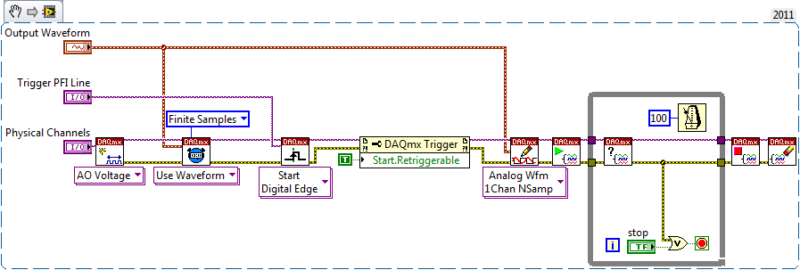
You must use the property start.retriggerable, something like this:
Best regards
-
Triggering off the coast of beginning of Pulse Audio in question DAQmx...
Hi guys,.
First of all, it is more a matter of software than hardware, so I didn't post this specific question in the multifunction DAQ card...
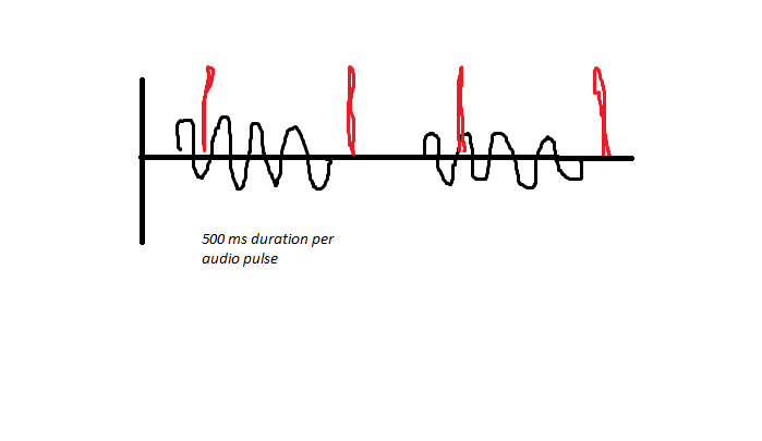
So I'll try to trigger an acquisition finished off the start of a pulse audio, however I have audio sync issues, due to the fact that it can be started before my VI runs. As noted below, the audio is generated and pulsed for 500ms on and 500 ms off the coast, and between these periods, a digital pulse is generated this way (shown in red). I have a problem to stay synchronized, due to the fact that I samples finished for 1 second of a data value, and if the USE EEG is faster than me, I can catch the pulse audio at Midway, rather than at the beginning.
I'm trigger analog outboard of a sound signal of 50mV and capturing two audio channels simultaneously and consistently captures 3 digital channels when they receive the trigger of the beginning of analog input trigger reference digital edge. If digital are slaves and audio is the master in this configuration. The point of this is to get a delta timed material at the time rather than use the timestamps of windows.
As I said, I use an Analog Edge Trigger Start to start my purchase, what triggers the digital task Digital Edge Start Trigger to start as well. How can I make sure that I start at the BEGINNING of a new pulse audio if I get out of sync, I can't understand this logic... Analog edge goes off just when it goes to the specified level, but maybe it's at half way through the 500ms pulse, so this is my problem...
I need to be a trigger to start because I do 55 000 this test iterations in a QMH Prod/consumer model and need relaxation to be redeclenchables and start-up is only redeclenchables.
The variability in timing you see at points 2 and 4 somewhat dictate against the possibility to set up a re-triggering precisely timed by the hardware configuration. I think that you need to abandon the idea of making repeated sampling finished back to back and switch volleys in a mode of continuous acquisition and treatment.
To help with this, I aim to capture the moments of digital via meter rather than DIO pulses and be ready to give up the acquisition rate noise much (if necessary) given that you said that your main concern is to distinguish between ON and OFF.
I must configure the counter to use the Digital pulse as a sample clock and use the sample clock signal HAVE the "time base", i.e. the signal which the edges will be counted and buffered in memory. This will give you 2 samples per second instead of 5 M and the values of the counter at these sampling points is the index in your AI data which occurred impulses. Pretty neat and clean. Just be sure to start the task of counter in front of the task to HAVE it.
-Kevin P
-
Hi, I have a digitizer PXI-5152 to two channels, one for read the voltage signal and the other to read the current signal to an electric discharge machining (EDM) process.
I want to count impulses generated in the process, for the moment, what does the code was the first to acquire number of data points and then pause to process data in a while loop to count the pulses on the rising or declining aboard trigger. The reason to do this is also some information of the data points are extracted in the while loop. But this way, I can't count all the geneated of legumes in the process because the acquisition and break the cycle.
Is it possible that I can write a code only permanently count impulses (rising or falling edge trigger) during the process? The process can take more than half an hour and number of generated pulses could be a few million?
Or do I need an additional card for the purpose?
Any help will be most appreciated!
Cook
It's here

-
False events to scanner high speed?
Hi all:
We use NI5154 1 GHz digitizer to capture the pulse of a detector. We have seen several very narrow pulses with a width smaller than single 10ns. In general, it would be a surprise to see these fast pulses in our detector. And also the associated ability seems to determine a time constant around 100 ns coming from any detector of signal. Someone argued that these narrow pulses can be false events reported by scanner. It's really hard for me to picture how this could happen? Furthermore, I use method of analog edge trigger in the capture of pulse process. We really need to clarify this issue. Any ideas will be appreciated.
An example of these impulses of snarrow figure was attached.
-------------------------------------------------
P. S.
Men of the United Kingdom sent us it there but on our narrow pulses. Here's a copy of his text:
"My first thought is that this may be due the digitizer itself, which gives.
events of thugs as the pulse fall time high level discriminator?
I've seen similar effects, even at 20 average scope projects with impulses from "form". It's
almost as if the discriminator FPGA is 'perfect' and sometimes reports
another pulse or two immediately after a 'real' pulse »
LCHEN5154 wrote:
Thanks much for your thoughts, Henrik.
If I see shoutcut entry. I don't know that these fast pulses are not generated randomly by digitizer.
The question is can scanner report short false events after an authentic event?
What a preamplifier ORTEC VT120A was used to amplify the signal. We have seen these impulses even without the amplifier.
Thank you.
Lixin
The specification of the ORTEC say output impedance is less than 1 Ohm, since we are talking about less than 1ns rise time: how long is the cable between the preamp and converter? I keep on thinking of cable... somehow, I feel that the output must also match the cable impededance...
You have shortened at the entrance of the digitizer? How to see cable as a room of ion or an antenna? You can try a termination 50 ohm or shorts instead of the preamp?
Looking at your signal: I see still two points within 5ns, how long is your cable? 5NS is equivalent to a 1.2 m cable 50 ohm...
Maybe you are looking for
-
I have a problem that the photo exhibition of Skype Contact on Skype for desktop PC, my Mobile Android phone and tablet, but when I use Skype in Outlook.com they do not. If I look in Skype Outlook.Com watch contact contacts but with no contact pictur
-
I want to delete cookies from sites variousTravel.
Try to book tours and sites to the top of their price whenever I visit. I think they know that I'm looking book, kind of 'Look at me' How do I get rid of their cookies without losing my history/bookmarks and passwords?
-
Remember - this is a public forum so never post private information such as numbers of mail or telephone! Ideas: I have xp sp2 installed, I've upgraded to sp3 it settled and went to restart, but used to charge up please help You have problems with pr
-
Hello members, Under Vista and several BSOD. Signature of the problem:Problem event name: BlueScreenThe system version: 6.0.6002.2.2.0.768.3Locale ID: 1033 More information about the problem:BCCode: 7fBCP1: 0000000000000008BCP2: 0000000080050031BCP3:
-
Junk 'Unread' becomes 'read' in the folder deleted
After that I have unread spam 'remove', some (but not all) appear as "read" in the deleted folder. Please can someone explain why this is happening?